Unit 7
Compensation of Control System
- In order to obtain the desired performance of the system, we use compensating networks. Compensating networks are applied to the system in the form of feed forward path gain adjustment.
- Compensate an unstable system to make it stable.
- A compensating network is used to minimize overshoot.
- These compensating networks increase the steady state accuracy of the system. An important point to be noted here is that the increase in the steady state accuracy brings instability to the system.
- Compensating networks also introduces poles and zeros in the system thereby causes changes in the transfer function of the system. Due to this, performance specifications of the system change.
Phase – Lead Compensation :-
The phase of output voltage leads the phase of input voltage for the applied sinusoidal input. The circuit diagram is shown below. The transfer function is given as,
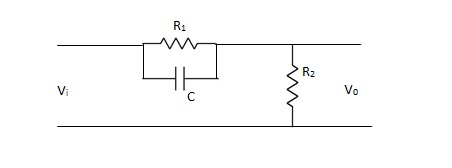
Vo/Vi = α(1 + ST)/(1 + S α T)
Where, α = R2/R1 + R2 and α< 1
T = R1C
w = 1/T lower corner frequency due to zero.
w = 1/ αT upper corner frequency due to pole.
Mid frequency is given as,
wm = 1/T√ α
The maximum phase lead angle is φm
Φm = tan-1(1- α)/2√α = Sin-11- α/1 + α
Phase Lag Compensation :-
The phase of the output voltage lags the phase of the input voltage for applied sinusoidal input. The circuit diagram is shown below,
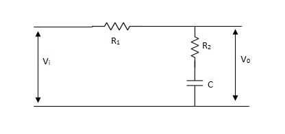
Vo/Vi = 1 + ST/1 + SβT
Where, β = R1 + R2/R2, β> 1
T = R2C
w = 1/T upper corner frequency due to zero
w= 1/βT lower corner frequency due to pole
The mid frequency wm,
wm = 1/T√β
The maximum phase lead angle Φm
Φm = tan-11- β/2 √β
= sin-11 – β/1 + β
Phase Lead Network Phase Lag Network
1>. It is used to improve the 1>It is used to improve the
Transient response. Steady state response.
2>. It acts as a high pass filter. 2>It acts as a low pass filter.
3>. The system becomes fast as 3>The Bandwidth decreases
Bandwidth increases as rise through rise time the speed
Time decreases. is slow.
4>. As the circuit acts as 4>Signal to noise ratio is higher as it a differentiator, signal to acts as integrator.
Noise ratio is poor.
5>. Maximum peak overshoot 5>It reduces steady state error thus
Is reduced. improve the steady state accuracy
Phase Lead-Lag Compensation:
For an unstable uncompensated system, lead compensation provides fast response but does not provide enough phase margin whereas lag compensation stabilises the system but does not provide enough bandwidth. So, we need multiple compensators in cascade. Below shown is a phase lead-lag compensator.
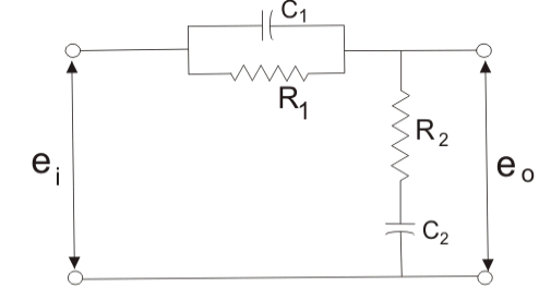
Fig: Phase Lead-Lag Compensator

Basic Concept of P,PI,PID Controller :
Effects of controller are viewed on time response and stability.
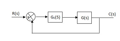
Gc(S) = TF of the controller
G(S) = OLTF without controller
G’(S) = Gc(S).G(S)
= OLTF with controller
(1). Proportional Controller :-
Proportional means scalar Multiplier.
Gc(S) = Kp Stability can be controlled
Q. G(S) = 1/S(S + 8)
CLTF = 1/S2 + 8S + 1
w2n = 1
wn = 1
2ξWn = 8
ξ = 4
ξ>/1 so, overdamped.
Now introducing Gc(S) = K
G’(S) = Kp/S(S + 8)
CLTF = Kp/S2 + 8S + Kp
wn = √Kp
2 ξwn = 8
ξ = 4/√Kp
If,
Kp = 16; ξ = 1; critically damped
Kp> 16; ξ< 1; undamped
Kp< 16; ξ> 1; overdamped
(2). Integral controller:-
The transfer function of this controller is
Gc(S) = Ki/S
Integral controller are used to improve the steady state response or reduce the steady state error.
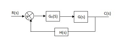
G’(S) = Gc(S).G(S)
G(S) = 1/S + 5, Gc(S) = Ki/S
G’(S) = Ki/S(S + 5). After applying the Gc(S) the type of system is increasing and hence, the steady state error is decreasing (Refer Time Response).
Disadvantage :-
By using integral controller the stability of closed loop system decreases.
G(S) = 1/S + 5
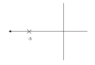
G’(S) = Ki/S(S + 5)
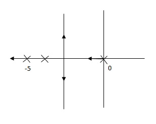
Fig(1), is more stable than (2) as more the away the pole from origin (imaginary axis) more is the stability.
Q. G(S) = 1/(S + 5)(S + 10)
G’(S) = Kp/S(S + 5)(S + 10)
G(S) = 1/(S + 5)(S + 10)
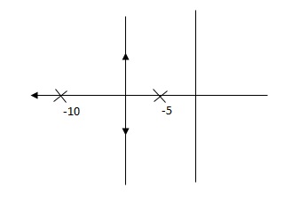
G’(S) = Ki/S(S + 5)(S + 10)
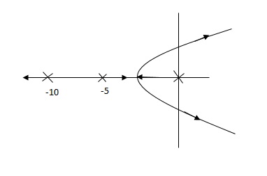
So, (b), is less stable at root locus lies on the R.H.S,
(3). Derivative Controller :-
Gc(S) = Kd(S)
They are used to improve the stability.
G’(S) = KdS/S2(S + 10)
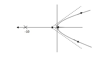
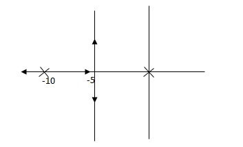
(b) is stable i.e. more stable than the (a).
Disadvantage :-
It increases the steady state i.e. o/p will not track the input at steady state.
(4). Proportional Plus Integral [PI] controller :-
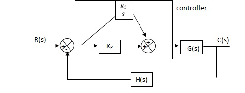
Gc(S) = KpS + Ki/S
The steady state error will decrease and the stability will depend on Kp i.e. if Kp is increased/decreased than according to it stability will change(Kpα stability).
Used to reduce ess without much affecting the stability.
(5). Proportional Plus Derivative Controller :-
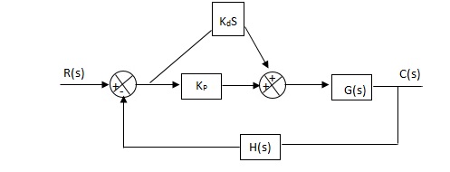
Used to improve the stability without affecting much the steady state error.
(6). PID controller :-
Gc(S) = Kp + Ki/S + KdS
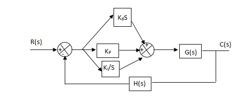
It improves the stability. It decreases the steady state error and both are proportional to Kp.
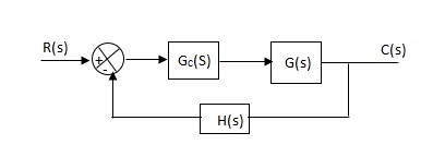
Q.The block diagram of a system using PI controllers is shown in the figure. Calculate :
(a). The steady state without and with controller for unit step input?
(b). Determine TF of newly constructed sys. With controller so, that a CL Poles is located at -5?

(a). Without :
C(S)/R(S) = 0.2/(S + 1)
C(S) = R(S) 0.2/(S + 1) + 0.2
For unit step
Ess = 1/1 + Kp
Kp = lt G(S)
S 0
= lt 0.2/(S + 1)
S 0
Kp = 0.2
Ess = 1/1.2 = 5/6 = 0.8
(b). With controller :
Gc(S) = Kp + Ki/S
G’(S) = Gc(S).G(S)
= ( Kp + Ki/S )0.2/(S + 1)
= (KpS + Ki)0.2/S(S + 1)
Ess = 1/1 + Kp = 0
So, the value of ess is decreased.
(b). Given
Kpi/Kp = 0.1
G’(S) = (Kp + Ki/S)(0.2/S + 1)
= (KpS + Ki)0.2/S(S + 1)
As a pole is to be added so, we have to examine the CE,
1 + G’(S) = 0
1 + (Kp + Ki)0.2/S(S + 1) = 0
S2 + S + 0.2KpS + 0.2Ki = 0
S2 + (0.2Kp + 1)S + 0.2Ki = 0
Given,
Kpi = 0.1Ki
Kp = 10Ki
S2 + (2Ki + 1)S + 0.2Ki = 0
Pole at S = -5
25 + (2Ki + 1)(-5) + 0.2Ki = 0
-10Ki – 5 + 25 + 0.2Ki = 0
-9.8Ki = -20
Ki = 2.05
Kp = 10Ki
= 20.5
Now,
G’(S) = (KpS + Ki)(0.2)/S(S + 1)
= (20.5S + 2.05)(0.2)/S(S + 1)
G’(S) = 4.1S + 0.41/S(S + 1)
Q.The block diagram of a system using Pd controller is shown, the PD is used to increase ξ to 0.8. Determine the T.F of controller?

(1). Kp = 1
Without controller:-
C(S)/R(S) = 16/S2 + 1.6S + 16
wn = 4
2 ξwn = 16
ξ = 1.6/2 x 4 = 0.2
(b). With derivative :-
ξS = 0.2 to 0.8
Undamped to critically damped,
G’(S) = (1 + KdS)(16)/(S2 + 1.6S)
CE:
S2 + 1.6S + 16(1 + KdS) = 0
S2 + (1.6 + Kd)S + 16 = 0
2 ξwn = 1.6 + Kd1.6
wn = 4
ξS = 0.8
2 x 4 x 0.8 = 1.6 + Kd1.6
6.4 – 1.6 = Kd1.6
4.8/16 = Kd
Kd = 0.3
TF = (1 + 0.3S)16/S(S + 16)
Reference Books :
- Modern Control Engineering by K.Ogata, Pearson Education.
2. Control Engineering by Kuo.