UNIT 3
MICROWAVE COMPONENTS
The waveguide system carries the power from the transmitter end to the input of an antenna. The entire waveguide system cannot be formed into one piece. Therefore, it should be constructed using many individual sections (or components), and these sections have to be connected with waveguide bends, joints, and so on.
A variety of signal control components such as directional couplers, circulators, isolators, attenuators, phase shifters, and multiport junctions have to be used in the microwave system. For example, waveguide attenuators and phase shifters are used to control the amplitude and to shift the phase, respectively. The isolators and circulators allow the microwave signals to travel in only one direction, whereas the directional couplers sample the power flowing in one direction and are used for determining the frequency and the level of power.
The microwave signal to be carried from one point to other is introduced into the waveguide with an antenna like probes or loops. The probe is coupled to the waveguide parallel to the point where the electric field is maximum, and the loops are coupled at a point where the magnetic field strength is maximum.
Probes :
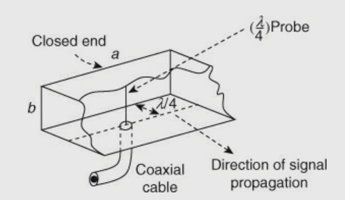
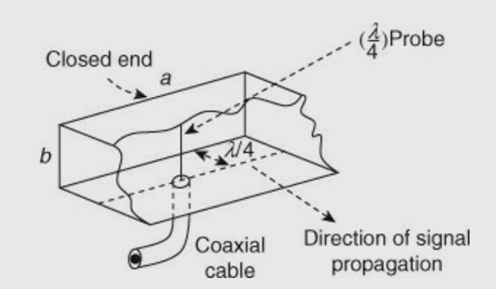
The probe is defined as a λ/ 4 vertical antenna that is inserted in the waveguide at a distance of λ/ 4 from the closed end and the center of the broader dimension of the waveguide (as shown in Figure ). It is inserted at that particular point, because there the electric field is maximum. The probe will now act as an antenna that is polarized in the plane parallel to that of an electric field.
Loops :
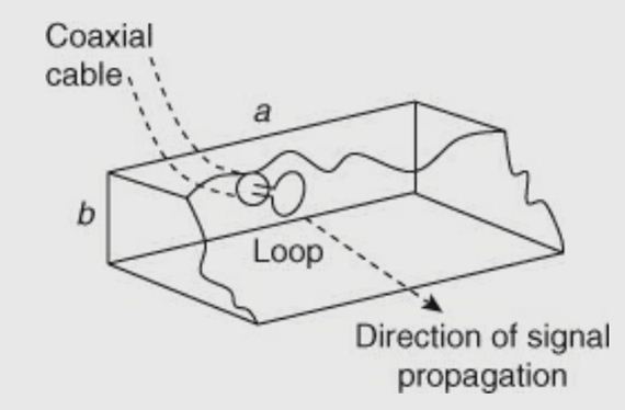
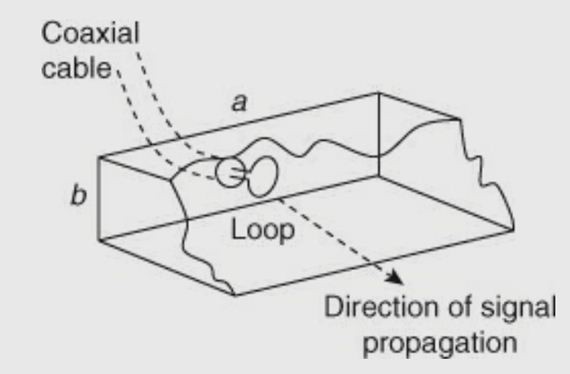
A loop can be used to introduce a magnetic field into a waveguide. It is generally mounted at a distance of λ/ 2 (or an integer multiple of λ/ 2) from the closed end of the waveguide. It can also be placed at the middle of the top wall or bottom wall (Figure ). Microwave energy applied through a short piece of coaxial cable causes a magnetic field to be set up in the loop. The magnetic field also establishes an electric field, which is then propagated down the waveguide. It is often desirable to couple a coaxial cable to a waveguide or a cavity resonator by means of a coupling loop rather than by a coupling probe.
An attenuator is a passive device that is used to reduce the strength or amplitude of a signal. At microwave frequencies, the attenuators were not only meant to do this, but also meant to maintain the characteristic impedance (Zo) of the system.
If the Zo of the transmission line is not maintained, the attenuator would be seen as impedance discontinuity, which causes reflections. Usually, a microwave attenuator controls the flow of microwave power by absorbing it. Attenuation in dB of a device is ten times the logarithmic ratio of power flowing into the device (Pi) to the power flowing out of the device (Po) when both the input and output circuits are matched.
Attenuation in dB = 10 log Pi /Po
In a microwave transmission system, the microwave power transferring from one section to another section can be controlled by a device known as microwave attenuator. These attenuators operate on the principle of interfering with electric or magnetic or both the fields. A resistive material placed in parallel to electric field lines (of field current) will induce a current in the material, which will result in loss. Thus, attenuation occurs by heating of the resistive element. Attenuators may be of two types:
Fixed
Mechanically or electronically variable
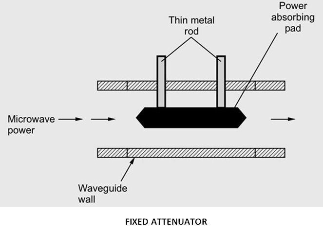
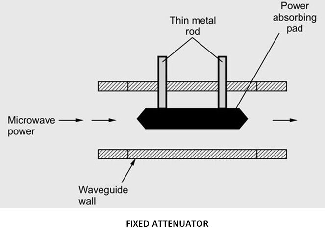
Fixed attenuators are used where a fixed amount of attenuation is needed. They also called pads. In this type of attenuator tapering is provided by placing a short section of a waveguide with an attached tapered plug of absorbing material at the end. The purpose of tapering is for the gradual transition of microwave power from the waveguide medium to the absorbing medium. Because of the absorbing medium, reflections at the media interface will be minimized. In a fixed attenuator, plug is nothing but a dielectric slab which has a glass slab with aquadog or a carbon film coating. The pad is placed in such a way that the plane is parallel to the electric field. For this, two thin metal rods are used.
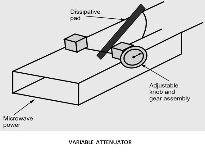
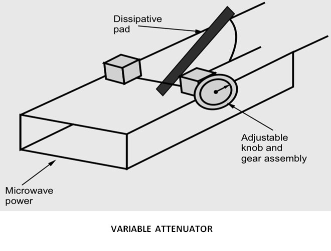
Variable attenuator provides continuous attenuation. The amount of attenuation
Introduced is controlled by the depth of insertion of absorbing plate inside the waveguide. For this a knob and gear assembly is used. The knob can be calibrated suitably. The maximum attenuation will be offered when the pad extends all the way across the guide.
The types of variable attenuators are :
Flap or resistive card type attenuators
Slide vane attenuators
Rotary vane attenuators
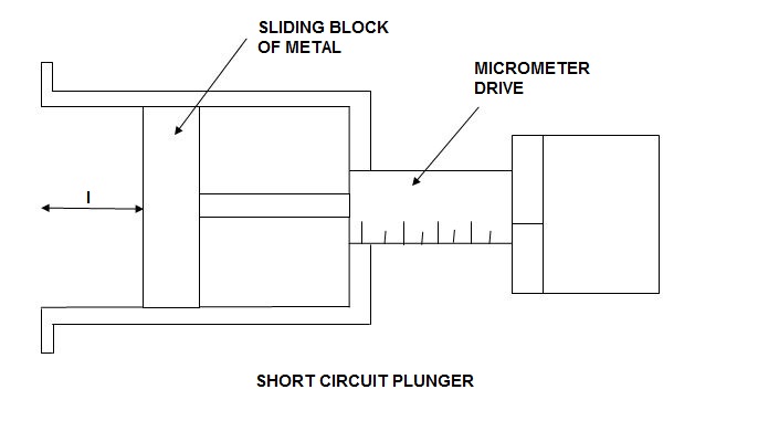
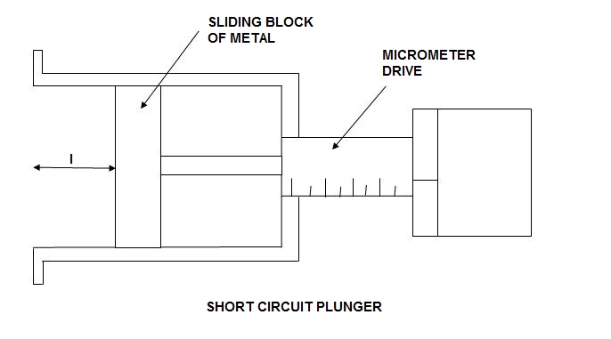
A shorting plunger or a short circuit plunger is a variable short circuit to provide an adjustable reactive load depending on the physical length of the line and hence reflects all the incident power. These terminations are used for measurements of impedance or scattering parameters of a microwave device or circuit element. The short is achieved by sliding a block of copper.
The main requirements for the design of a short circuit plunger are :
- Low contact resistance at the guide wall.
- Constant contact resistance for movement along the line.
Waveguide Tees are used for the purpose of connecting a branch or a section of a waveguide in a series or parallel to the main waveguide. The intersection of waveguides in the shape of the English capital letter “T” is called a T junction.
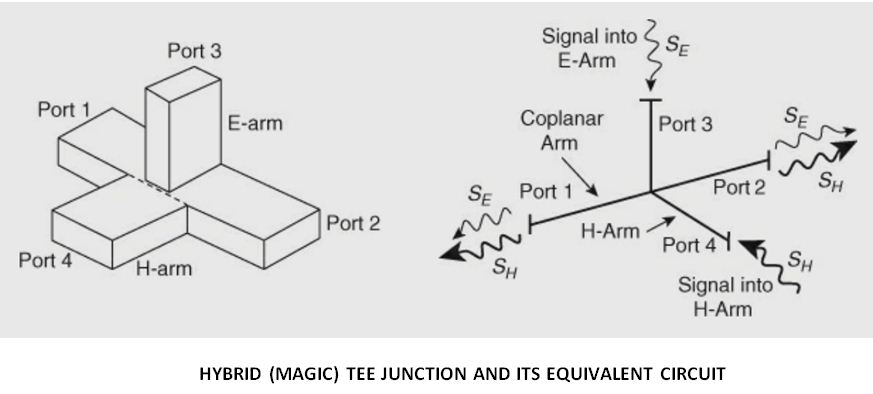
The combination of an E-plane Tee and an H-plane Tee is called as Magic Tee. A Magic Tee can be formed by attaching arms to the slots made in the broad and narrow walls of a waveguide. It is also called as hybrid tee in which the power distributes equally between the output ports. The outputs may have 0 ° or 180 ° phase difference. Magic Tee is a 3db hybrid coupler which is also called as an anti-symmetric coupler. If one of the coplanar arm is terminated, then the power delivered to another coplanar arm is independent of terminated port.
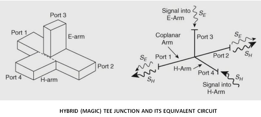
Its characteristics are as follows:
Let us consider two waves whose magnitude and phase are equal. If we feed these waves to ports 1 and 2, the outputs at port 3 and port 4 will be zero and additive respectively. The power distributes equally at ports 1 and 2 if a wave is incident at port 4 and no power will appear at port 3.
The power at ports 1 and 2 appears with an equal magnitude and the opposite phase if a wave is incident at port 3 and no power will appear at port 4. If a wave is incident on any one of the coplanar arms i.e., port 1 or port 2, then no power will appear at other coplanar arm i.e., port 2 or port 1. This is due to the occurring of phase delay and phase advance in E arm and H arm respectively. In Magic Tee the imaginary plane bisects arms 3 and 4 symmetrically. There will not be any reflections in the junction, if ports 1 and 2 are terminated with matched loads. Since all the ports are the collinear arm ports in Magic Tee, they are perfectly matched to the junction, and the E and H arm ports are decoupled individually The signal distributes equally between the E and H arms, if signal is incident on collinear arm then, output signal is given as Pout=Pin/2 and Aout=Ain/√2
A signal into the H arm splits equally between the collinear arms, the outputs being in phase, equidistant from the junction. A signal into the E arm splits equally between the collinear arms, the outputs being out of phase, equidistant from the junction. For signals into both collinear arms.
- The signal output from the E arm is equal to 1/√2 times the phasor difference of the input signals. (Difference arm)
2. The signal output from the H arm is equal to 1/√2 times the phasor sum of the input signals. (Sum arm ).
Advantages of magic tee :
Due to the decoupling property of output ports, the power delivered to one of the output ports becomes independent of the termination at the other output port.
In the E-or H-plane Tee, the power division between ports depends on terminations existing at the respective output ports; but in Magic Tee (in which all the ports are perfectly matched), power division between the ports is independent of terminations.
Disadvantages of magic tee :
There is an impedance mismatch at the junctions, when a signal is applied to any arm of the Magic Tee. Because of this impedance mismatch the flow of energy in the output arms is affected by reflections. These reflections cause the following two disadvantages of Magic Tee :
When all the energy that is fed into the junction does not reach the load due the reflections, it results in power loss.
The standing waves that are produced due to reflections can result in internal arcing. Thus, it results in reduction of the maximum power that a Magic Tee can handle.
Applications of magic tee :
A magic tee has many applications as follows :
1. As an isolator
2. As a matching device
3. As a phase shifter
4. As a duplexer
5. As a mixer
6. As a measurement of impedance
The directional coupler is a 4–port reciprocal device. Direction couplers consist of two transmission lines and a mechanism for coupling signals between them.
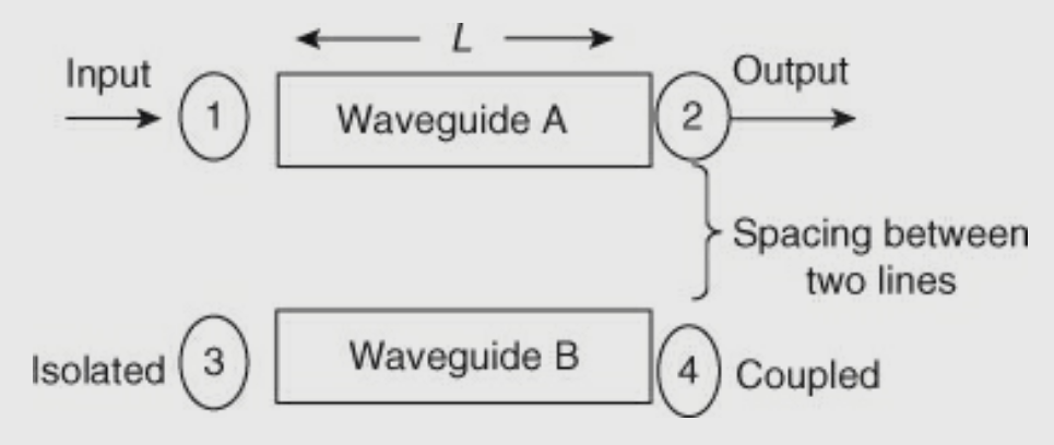
A coupler is a device that consists of two waveguides which are placed very close to each other.
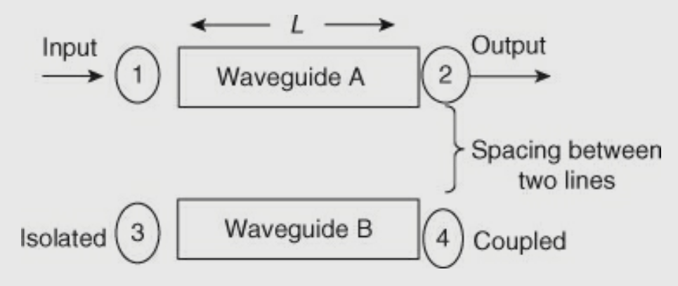
A portion of energy traveling in waveguide A will be coupled on waveguide B.
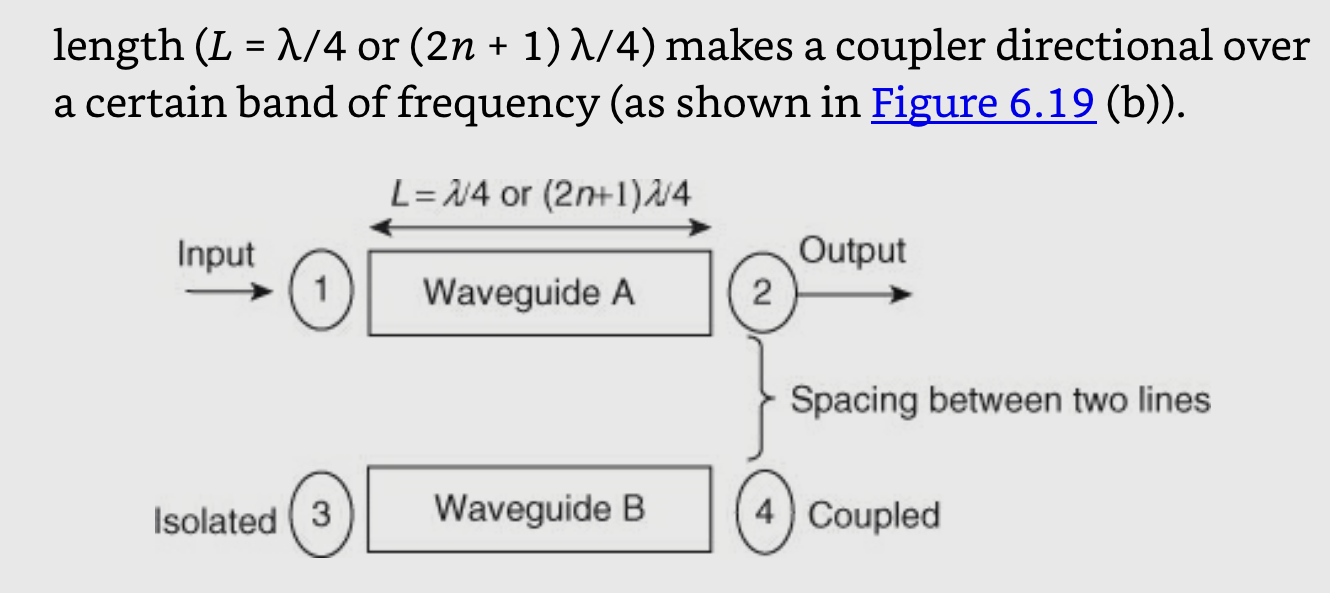
The term directional means that the energy is passed in one direction only, and no energy passes in the reverse direction. The directional property is obtained by using a specific length (L) of a transmission line, that is, a quarter wavelength (λ/ 4). A λ/ 4 transmission line offers high impedance at one end and low impedance at the other end. The specific length (L = λ/ 4 or (2n + 1) λ/ 4) makes a coupler directional over a certain band of frequency.
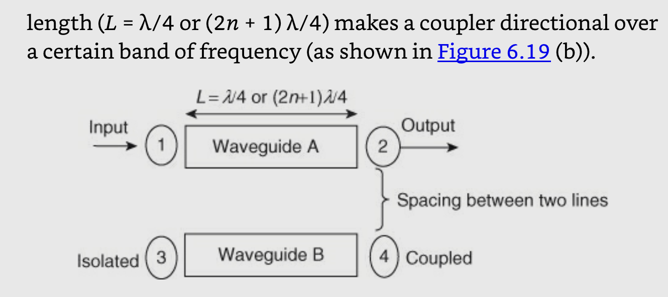
Power flow in a directional coupler :
The power incident at port 1 (input) is split between two other ports ( port 4 (coupled) and port 2 (output)), and no power appears from port 3 (isolated).
Pi or P1 = power incident at port 1
Pf or P2 = forward power or output power at port 2
Pb or P3 = reflected power at isolated port 3 in secondary waveguide
Pfc or P4 = forward coupled power in the secondary waveguide, that is, at port 4.
The properties of an ideal directional coupler are as follows:
In an ideal directional coupler, all the four ports are perfectly matched and also ports1,3 and ports 2, 4 are perfectly isolated.
A portion of the wave is coupled to port 4 but not coupled to port 3 which is traveling from port 1 to port 2. Similarly, a portion of the wave travelling from port 2 to port 1 is coupled to port 3 but not to port 4.
Likewise, the portion of the wave traveling from port 4 to port 3 is coupled to port 1 but not to port 2. Similarly, a portion of the wave traveling from port 3 to port 4 is coupled to port 2 but not to port 1.
The coupling between port 1 and port 4 is similar to that between port 2 and port 3, and the degree of coupling depends on the structure of the coupler.
The outputs are always in phase quadrature; that is, they exhibit a phase difference of 90 degrees. For this reason, a directional coupler is called a quadrature-type hybrid.
Types of directional couplers :
There are two types of directional couplers; both are four-port components and are reciprocal. They are :
Two-hole directional coupler and,
Single-hole or Bethe-hole directional coupler
Parameters that Characterize the Directional Coupler :
A directional coupler is characterized by 3 parameters:
Coupling factor
Directivity
Isolation
Coupling factor (C): It indicates the fraction of input power coupled to the coupled port.
Directivity (D): Directivity is the ability to isolate coupled (port 4) and backward (port 3) ports.
Isolation (I): Isolation is defined as the ratio of power incident to the power coupled in the isolated port and is expressed in dB.
Applications of Directional Couplers :
Directional couplers are extensively used in systems that measure the amplitude and phase of traveling waves. The major applications are as follows:
Power monitoring and source leveling
SWR measurements
In unidirectional power measurements
In reflectometers
Unidirectional wave launching
Isolation of signal sources
A phase shifter is a two-port component that provides a fixed or variable change in the phase of the traveling wave. An ideal phase shifter is lossless and matched. It only shifts the phase of the output wave.
Fixed phase shifters are usually extra transmission-line sections of a certain length that are meant to shift the phase with regard to the reference line. Therefore, depending on the bias current, the wave traveling along the transmission line will have an additional traveling path. Since these devices are binary switches, only discrete phase shifts are possible.
The variable phase shifters use mechanical or electronic means to achieve a dynamic range of phase difference. The mechanically tuned phase shifter usually consists of variable short circuits that are used with hybrids or, in the case of waveguide components, a dielectric slab with a variable position in the guide. Step motors move the slab across the guide (from its center toward the outer walls), there by accomplishing a maximum or minimum phase shift. Another method for obtaining the desired mechanically tuned phase shift involves combining variable short circuits and hybrid circuits. The movement of the short circuit along a transmission line results in the phase shift, thus making it appear shorter or longer.
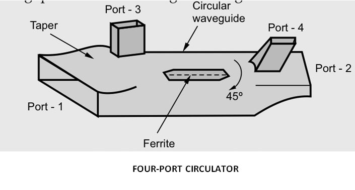
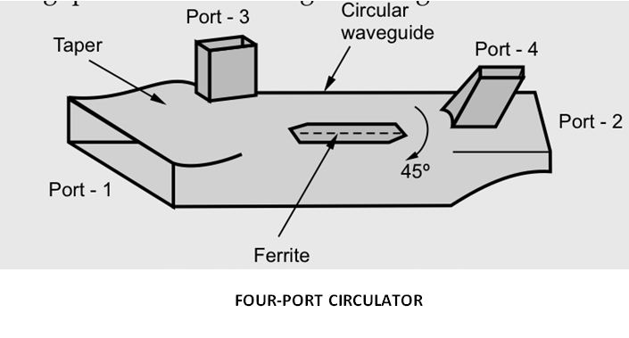
A microwave circulator is a multiport device in which power is circulated from nth port to (n + 1)th port only in one direction. A four port circulator is most commonly used. Circulator is a non-reciprocal component. All the four ports arematched and transmission of power takes place in cyclic order only. An ideal circulator is perfectly lossless.
Working of circulator is based on principle of Faraday rotation. All the ports 1,2,3, and 4, are oriented such that the E-field of transmitted signal couples to these ports successively after going through a rotation of 45 degrees in clockwise direction.
In a four-port Faraday rotation circulator, power entering port-1 travels along the magnetized ferrite. The direction of the E field vector gets rotated by 45. Therefore power entered at port-1 appears at port-2. The power cannot be coupled to port-4 because ports-2 and 4 are 90 out of phase. Similarly, port-3 is coupled to port-4 and port-4 to port-1.
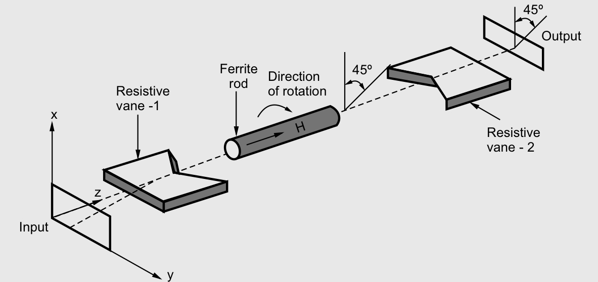
Isolator is a non-reciprocal ferrite transmission device. Isolators are generally used to improve the frequency stability of microwave generators. Isolators transmits electromagnetic wave only in one direction, the reflected wave is attenuated (absorbed). Thus microwave generating active devices are isolated. An ideal isolator completely absorbs power of propagation in one direction and provides lossless transmission in the opposite direction. The Faraday rotation isolator provides 1 dB insertion loss in forward transmission and about 20 to 30 dB isolation in reverse direction. Isolators can be produced by inserting a ferrite rod along the axis of a rectangular waveguide.
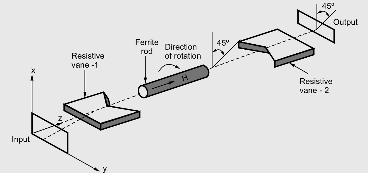
Let the incident wave has E in x-direction when it propagates through ferrite rod, it is rotated by 45. It is launched into waveguide which is at 45. Reflected wave from load travels in reverse direction and is again rotated by 45 by ferrite rod. Reflected E appearing at resistive vane-1 is in y-direction and it is completely attenuated
References
Text Books:
- Microwave devices and circuits by Samuel Y. Laio, PHI.
Reference Books:
1. Microwave & Radar Engineering by M. Kulkarni, Umesh Publications.
2. Foundations of Microwave Engineering by R.F. Collins, McGraw Hill.
3. Microwave Principles by Reich et. Al. , Van Hestrand
4. Communication in Space by Jaffen, Halt Renetat Winston.
————————————————- o ————————————————
UNIT 3
MICROWAVE COMPONENTS
The waveguide system carries the power from the transmitter end to the input of an antenna. The entire waveguide system cannot be formed into one piece. Therefore, it should be constructed using many individual sections (or components), and these sections have to be connected with waveguide bends, joints, and so on.
A variety of signal control components such as directional couplers, circulators, isolators, attenuators, phase shifters, and multiport junctions have to be used in the microwave system. For example, waveguide attenuators and phase shifters are used to control the amplitude and to shift the phase, respectively. The isolators and circulators allow the microwave signals to travel in only one direction, whereas the directional couplers sample the power flowing in one direction and are used for determining the frequency and the level of power.
The microwave signal to be carried from one point to other is introduced into the waveguide with an antenna like probes or loops. The probe is coupled to the waveguide parallel to the point where the electric field is maximum, and the loops are coupled at a point where the magnetic field strength is maximum.
Probes :
The probe is defined as a λ/ 4 vertical antenna that is inserted in the waveguide at a distance of λ/ 4 from the closed end and the center of the broader dimension of the waveguide (as shown in Figure ). It is inserted at that particular point, because there the electric field is maximum. The probe will now act as an antenna that is polarized in the plane parallel to that of an electric field.
Loops :
A loop can be used to introduce a magnetic field into a waveguide. It is generally mounted at a distance of λ/ 2 (or an integer multiple of λ/ 2) from the closed end of the waveguide. It can also be placed at the middle of the top wall or bottom wall (Figure ). Microwave energy applied through a short piece of coaxial cable causes a magnetic field to be set up in the loop. The magnetic field also establishes an electric field, which is then propagated down the waveguide. It is often desirable to couple a coaxial cable to a waveguide or a cavity resonator by means of a coupling loop rather than by a coupling probe.
An attenuator is a passive device that is used to reduce the strength or amplitude of a signal. At microwave frequencies, the attenuators were not only meant to do this, but also meant to maintain the characteristic impedance (Zo) of the system.
If the Zo of the transmission line is not maintained, the attenuator would be seen as impedance discontinuity, which causes reflections. Usually, a microwave attenuator controls the flow of microwave power by absorbing it. Attenuation in dB of a device is ten times the logarithmic ratio of power flowing into the device (Pi) to the power flowing out of the device (Po) when both the input and output circuits are matched.
Attenuation in dB = 10 log Pi /Po
In a microwave transmission system, the microwave power transferring from one section to another section can be controlled by a device known as microwave attenuator. These attenuators operate on the principle of interfering with electric or magnetic or both the fields. A resistive material placed in parallel to electric field lines (of field current) will induce a current in the material, which will result in loss. Thus, attenuation occurs by heating of the resistive element. Attenuators may be of two types:
Fixed
Mechanically or electronically variable
Fixed attenuators are used where a fixed amount of attenuation is needed. They also called pads. In this type of attenuator tapering is provided by placing a short section of a waveguide with an attached tapered plug of absorbing material at the end. The purpose of tapering is for the gradual transition of microwave power from the waveguide medium to the absorbing medium. Because of the absorbing medium, reflections at the media interface will be minimized. In a fixed attenuator, plug is nothing but a dielectric slab which has a glass slab with aquadog or a carbon film coating. The pad is placed in such a way that the plane is parallel to the electric field. For this, two thin metal rods are used.
Variable attenuator provides continuous attenuation. The amount of attenuation
Introduced is controlled by the depth of insertion of absorbing plate inside the waveguide. For this a knob and gear assembly is used. The knob can be calibrated suitably. The maximum attenuation will be offered when the pad extends all the way across the guide.
The types of variable attenuators are :
Flap or resistive card type attenuators
Slide vane attenuators
Rotary vane attenuators
A shorting plunger or a short circuit plunger is a variable short circuit to provide an adjustable reactive load depending on the physical length of the line and hence reflects all the incident power. These terminations are used for measurements of impedance or scattering parameters of a microwave device or circuit element. The short is achieved by sliding a block of copper.
The main requirements for the design of a short circuit plunger are :
- Low contact resistance at the guide wall.
- Constant contact resistance for movement along the line.
Waveguide Tees are used for the purpose of connecting a branch or a section of a waveguide in a series or parallel to the main waveguide. The intersection of waveguides in the shape of the English capital letter “T” is called a T junction.
The combination of an E-plane Tee and an H-plane Tee is called as Magic Tee. A Magic Tee can be formed by attaching arms to the slots made in the broad and narrow walls of a waveguide. It is also called as hybrid tee in which the power distributes equally between the output ports. The outputs may have 0 ° or 180 ° phase difference. Magic Tee is a 3db hybrid coupler which is also called as an anti-symmetric coupler. If one of the coplanar arm is terminated, then the power delivered to another coplanar arm is independent of terminated port.
Its characteristics are as follows:
Let us consider two waves whose magnitude and phase are equal. If we feed these waves to ports 1 and 2, the outputs at port 3 and port 4 will be zero and additive respectively. The power distributes equally at ports 1 and 2 if a wave is incident at port 4 and no power will appear at port 3.
The power at ports 1 and 2 appears with an equal magnitude and the opposite phase if a wave is incident at port 3 and no power will appear at port 4. If a wave is incident on any one of the coplanar arms i.e., port 1 or port 2, then no power will appear at other coplanar arm i.e., port 2 or port 1. This is due to the occurring of phase delay and phase advance in E arm and H arm respectively. In Magic Tee the imaginary plane bisects arms 3 and 4 symmetrically. There will not be any reflections in the junction, if ports 1 and 2 are terminated with matched loads. Since all the ports are the collinear arm ports in Magic Tee, they are perfectly matched to the junction, and the E and H arm ports are decoupled individually The signal distributes equally between the E and H arms, if signal is incident on collinear arm then, output signal is given as Pout=Pin/2 and Aout=Ain/√2
A signal into the H arm splits equally between the collinear arms, the outputs being in phase, equidistant from the junction. A signal into the E arm splits equally between the collinear arms, the outputs being out of phase, equidistant from the junction. For signals into both collinear arms.
- The signal output from the E arm is equal to 1/√2 times the phasor difference of the input signals. (Difference arm)
2. The signal output from the H arm is equal to 1/√2 times the phasor sum of the input signals. (Sum arm ).
Advantages of magic tee :
Due to the decoupling property of output ports, the power delivered to one of the output ports becomes independent of the termination at the other output port.
In the E-or H-plane Tee, the power division between ports depends on terminations existing at the respective output ports; but in Magic Tee (in which all the ports are perfectly matched), power division between the ports is independent of terminations.
Disadvantages of magic tee :
There is an impedance mismatch at the junctions, when a signal is applied to any arm of the Magic Tee. Because of this impedance mismatch the flow of energy in the output arms is affected by reflections. These reflections cause the following two disadvantages of Magic Tee :
When all the energy that is fed into the junction does not reach the load due the reflections, it results in power loss.
The standing waves that are produced due to reflections can result in internal arcing. Thus, it results in reduction of the maximum power that a Magic Tee can handle.
Applications of magic tee :
A magic tee has many applications as follows :
1. As an isolator
2. As a matching device
3. As a phase shifter
4. As a duplexer
5. As a mixer
6. As a measurement of impedance
The directional coupler is a 4–port reciprocal device. Direction couplers consist of two transmission lines and a mechanism for coupling signals between them.
A coupler is a device that consists of two waveguides which are placed very close to each other.
A portion of energy traveling in waveguide A will be coupled on waveguide B.
The term directional means that the energy is passed in one direction only, and no energy passes in the reverse direction. The directional property is obtained by using a specific length (L) of a transmission line, that is, a quarter wavelength (λ/ 4). A λ/ 4 transmission line offers high impedance at one end and low impedance at the other end. The specific length (L = λ/ 4 or (2n + 1) λ/ 4) makes a coupler directional over a certain band of frequency.
Power flow in a directional coupler :
The power incident at port 1 (input) is split between two other ports ( port 4 (coupled) and port 2 (output)), and no power appears from port 3 (isolated).
Pi or P1 = power incident at port 1
Pf or P2 = forward power or output power at port 2
Pb or P3 = reflected power at isolated port 3 in secondary waveguide
Pfc or P4 = forward coupled power in the secondary waveguide, that is, at port 4.
The properties of an ideal directional coupler are as follows:
In an ideal directional coupler, all the four ports are perfectly matched and also ports1,3 and ports 2, 4 are perfectly isolated.
A portion of the wave is coupled to port 4 but not coupled to port 3 which is traveling from port 1 to port 2. Similarly, a portion of the wave travelling from port 2 to port 1 is coupled to port 3 but not to port 4.
Likewise, the portion of the wave traveling from port 4 to port 3 is coupled to port 1 but not to port 2. Similarly, a portion of the wave traveling from port 3 to port 4 is coupled to port 2 but not to port 1.
The coupling between port 1 and port 4 is similar to that between port 2 and port 3, and the degree of coupling depends on the structure of the coupler.
The outputs are always in phase quadrature; that is, they exhibit a phase difference of 90 degrees. For this reason, a directional coupler is called a quadrature-type hybrid.
Types of directional couplers :
There are two types of directional couplers; both are four-port components and are reciprocal. They are :
Two-hole directional coupler and,
Single-hole or Bethe-hole directional coupler
Parameters that Characterize the Directional Coupler :
A directional coupler is characterized by 3 parameters:
Coupling factor
Directivity
Isolation
Coupling factor (C): It indicates the fraction of input power coupled to the coupled port.
Directivity (D): Directivity is the ability to isolate coupled (port 4) and backward (port 3) ports.
Isolation (I): Isolation is defined as the ratio of power incident to the power coupled in the isolated port and is expressed in dB.
Applications of Directional Couplers :
Directional couplers are extensively used in systems that measure the amplitude and phase of traveling waves. The major applications are as follows:
Power monitoring and source leveling
SWR measurements
In unidirectional power measurements
In reflectometers
Unidirectional wave launching
Isolation of signal sources
A phase shifter is a two-port component that provides a fixed or variable change in the phase of the traveling wave. An ideal phase shifter is lossless and matched. It only shifts the phase of the output wave.
Fixed phase shifters are usually extra transmission-line sections of a certain length that are meant to shift the phase with regard to the reference line. Therefore, depending on the bias current, the wave traveling along the transmission line will have an additional traveling path. Since these devices are binary switches, only discrete phase shifts are possible.
The variable phase shifters use mechanical or electronic means to achieve a dynamic range of phase difference. The mechanically tuned phase shifter usually consists of variable short circuits that are used with hybrids or, in the case of waveguide components, a dielectric slab with a variable position in the guide. Step motors move the slab across the guide (from its center toward the outer walls), there by accomplishing a maximum or minimum phase shift. Another method for obtaining the desired mechanically tuned phase shift involves combining variable short circuits and hybrid circuits. The movement of the short circuit along a transmission line results in the phase shift, thus making it appear shorter or longer.
A microwave circulator is a multiport device in which power is circulated from nth port to (n + 1)th port only in one direction. A four port circulator is most commonly used. Circulator is a non-reciprocal component. All the four ports arematched and transmission of power takes place in cyclic order only. An ideal circulator is perfectly lossless.
Working of circulator is based on principle of Faraday rotation. All the ports 1,2,3, and 4, are oriented such that the E-field of transmitted signal couples to these ports successively after going through a rotation of 45 degrees in clockwise direction.
In a four-port Faraday rotation circulator, power entering port-1 travels along the magnetized ferrite. The direction of the E field vector gets rotated by 45. Therefore power entered at port-1 appears at port-2. The power cannot be coupled to port-4 because ports-2 and 4 are 90 out of phase. Similarly, port-3 is coupled to port-4 and port-4 to port-1.
Isolator is a non-reciprocal ferrite transmission device. Isolators are generally used to improve the frequency stability of microwave generators. Isolators transmits electromagnetic wave only in one direction, the reflected wave is attenuated (absorbed). Thus microwave generating active devices are isolated. An ideal isolator completely absorbs power of propagation in one direction and provides lossless transmission in the opposite direction. The Faraday rotation isolator provides 1 dB insertion loss in forward transmission and about 20 to 30 dB isolation in reverse direction. Isolators can be produced by inserting a ferrite rod along the axis of a rectangular waveguide.
Let the incident wave has E in x-direction when it propagates through ferrite rod, it is rotated by 45. It is launched into waveguide which is at 45. Reflected wave from load travels in reverse direction and is again rotated by 45 by ferrite rod. Reflected E appearing at resistive vane-1 is in y-direction and it is completely attenuated
References
Text Books:
- Microwave devices and circuits by Samuel Y. Laio, PHI.
Reference Books:
1. Microwave & Radar Engineering by M. Kulkarni, Umesh Publications.
2. Foundations of Microwave Engineering by R.F. Collins, McGraw Hill.
3. Microwave Principles by Reich et. Al. , Van Hestrand
4. Communication in Space by Jaffen, Halt Renetat Winston.
————————————————- o ————————————————