UNIT 5
ANTENNA
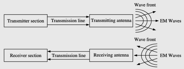
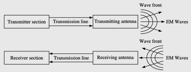
An antenna is a device used for efficient radiation of electromagnetic energy (radio waves) into free space. As per the IEEE standard definitions, “an antenna is a device that converts electronic signals to electromagnetic waves and vice-versa with minimum loss of signals”.
It is the vital link to establish connectivity between transmitter and free space or free space and receiver. The purpose of transmitting antenna is to radiate maximum possible RF power (watts/kilowatts/dB)either in all directions (omni-directional antenna) or in a specified direction (directional antenna) whereas the purpose of receiving antenna is to intercept the maximum RF power which is sufficiently large compared to noise existing within receiver’s bandwidth. It is to be noted that the power received by the receiving antenna is generally of the order of microwatts and picowatts. In true sense, antennas act like transducers that transfers electromagnetic energy between transmission line and free space or antenna acts as an interface between transmission line and free space.
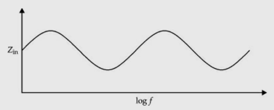
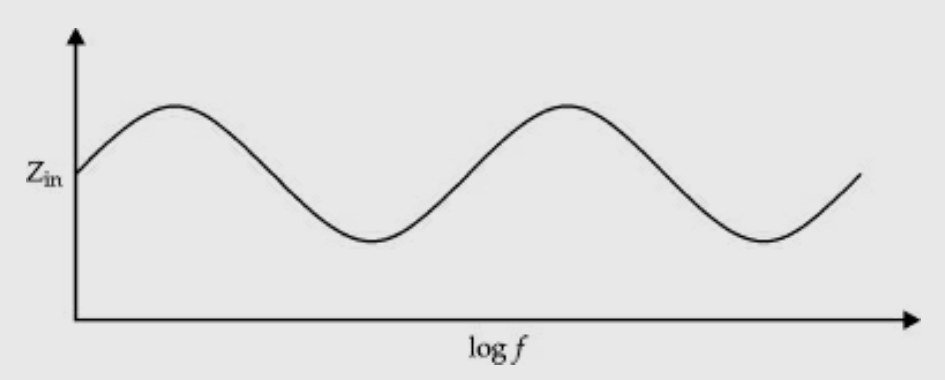
It is an array antenna which has structural geometry such that its impedance is periodic with the logarithm of the frequency.
It is a non-linear array in which the spacing of the elements as well as their dimensions are unequal. However, excitation is uniform. It is basically called a frequency-independent
Antenna. It can be used to receive a good number of TV channels without any 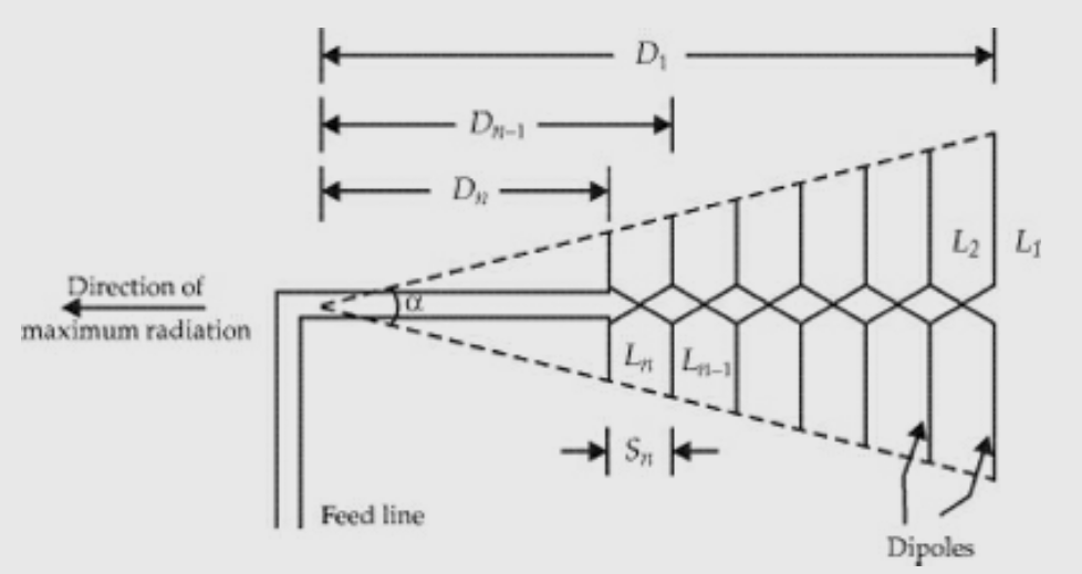
deterioration of the received field strength.
Features :
- It is a frequency-independent antenna.
- The input impedance variation of the antenna with the log of frequency is periodic and hence the name.
- It is an array of non-identical dipoles which are all excited equally.
- Is a non-uniform array where the spacing between the elements is unequal.
- Its impedance, directional patterns and directivity are constant with frequency.
- The gain of a well-designed antenna lies between 7.5 and 12 dB.
- It is a broad band antenna.
- It has uni-directional characteristics.
- There are a variety of log-periodic structures and all of them are not frequency-independent.
- They are used in VHF and UHF bands.
- They are used for TV reception and can receive a number of channels.
- The planar trapezoidal and wire trapezoidal tooth log-periodic antennas can be used.
- It is more efficient than Rhombic antenna.
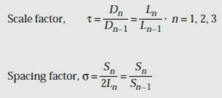
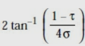
The design equations are :
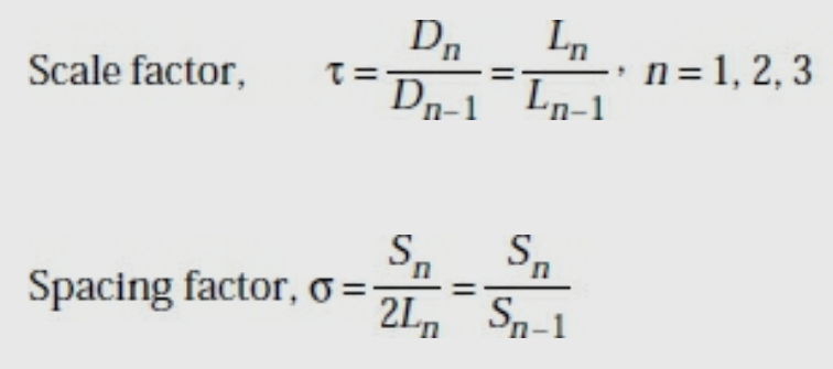
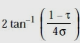
Where a = wedge angle or included angle =
The analysis of log-periodic array is described in terms of three regions.
Capacitive In this region, the elements are shorter than λ/2 and they are capacitive. Hence the current leads the applied voltage by 90°. These elements produce small backward radiation.
Resistive Here the dipoles are of length and they are resistive. The currents are large and they are in phase with the voltage. These elements produce considerable forward radiation.
Inductive Here elements are of length > λ/2 .The currents lag the voltage by 90°. The element reflects the incident wave in the backward direction.
It is a radiating element formed by a slot in a metallic surface. An opening cut in a conducting sheet or in one of the walls of the waveguide acts as the antenna. It is excited suitably either by a co-axial cable or through the waveguide.
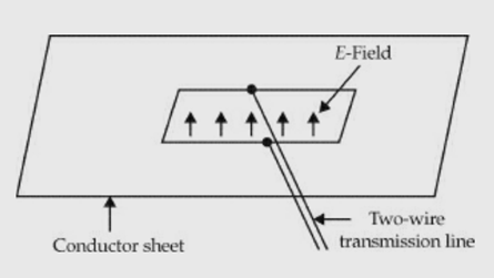
Slot antenna excited by two – wire line
Features :
- A basic slot has a length of λ/2 and its width is much less than λ/2 .
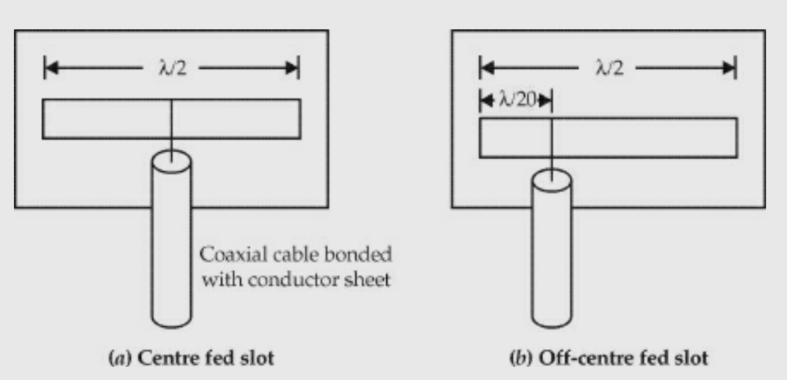
2. Slots are usually excited by a co-axial cable at a distance of about 0.05λ from one end of the slot to get reasonable impedance properties.
3. A horizontal slot with such an excitation produces vertical polarisation and vice-versa. In fact, the slot radiates from both sides.
4. If the slot is boxed with an internal dimension of λ/4 ,the radiation is outward from the opening of the box.
5. A slot and a dipole of length have similar gain and radiation characteristics. But there is a difference in polarisation.
6. In order to increase the gain and directivity, array of slots is used.
7. Cylindrical arrays of slots are found to produce omni-directional radiation in the horizontal plane with horizontal polarisation.
8. When a high frequency field exists across a thin slot in a conducting plane, it radiates.
9. A slot excited by a two-wire line. The electric field in the λ/2 slot is sinusoidal.
10. The impedance of such an excited slot is purely resistive and is 365 ohms.
A dipole and a slot in a conducting sheet have similar shapes except that the metal region and free space are interchanged.
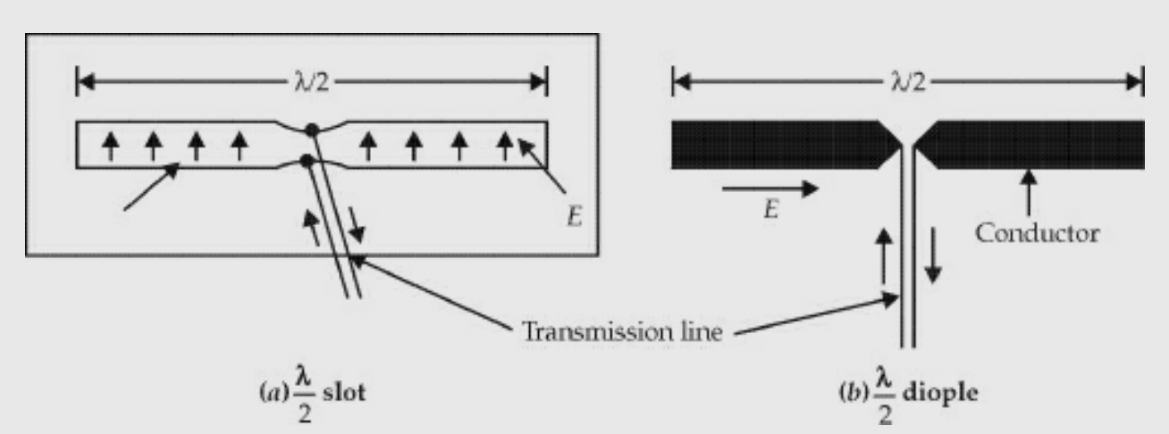
The main difference is that the slot of Fig (a) is vertically polarised and dipole of Fig.(b) is horizontally polarised.

The slot and dipole impedances are related by
Intrinsic impedance = 377 Ω
If the width of the dipole is very small, w <<λ.
Then Zd = 73 + j42.5Ω
Slot impedance, Zs =

Zs = 363 − j211 ohms
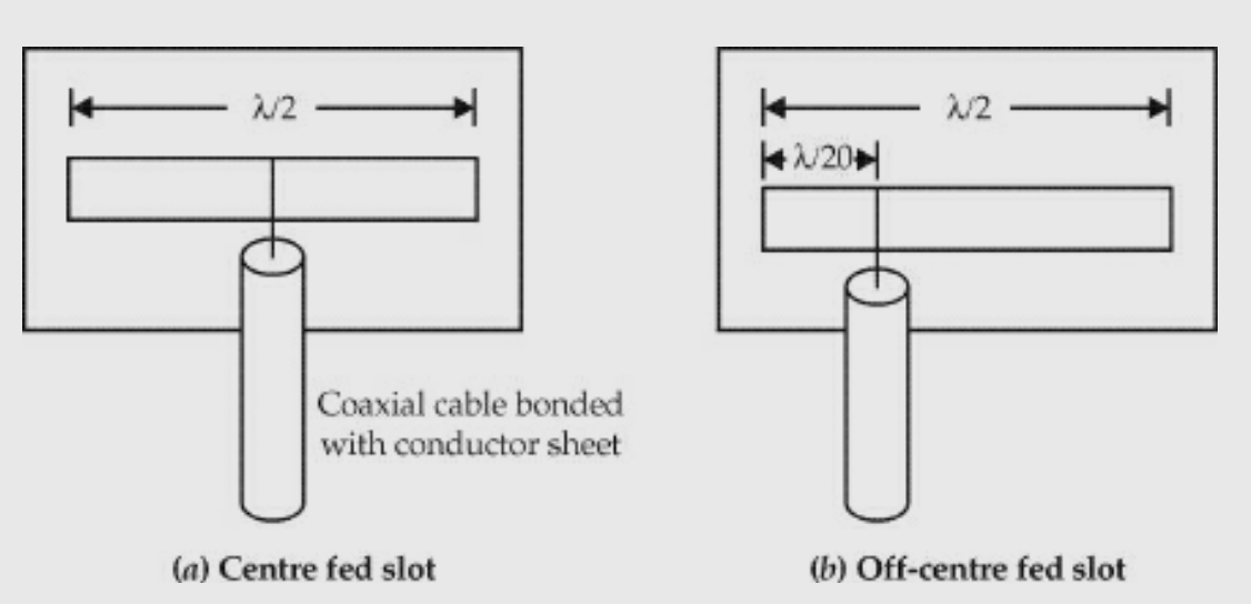
By changing the feed point from one end of the slot, its impedance can be changed. For example, two slots of different feed points are shown in Figs(a) and (b).
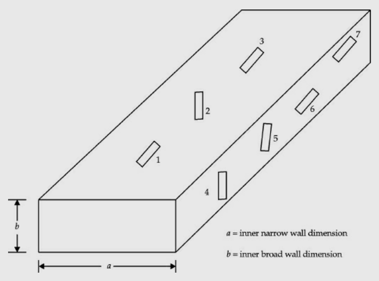
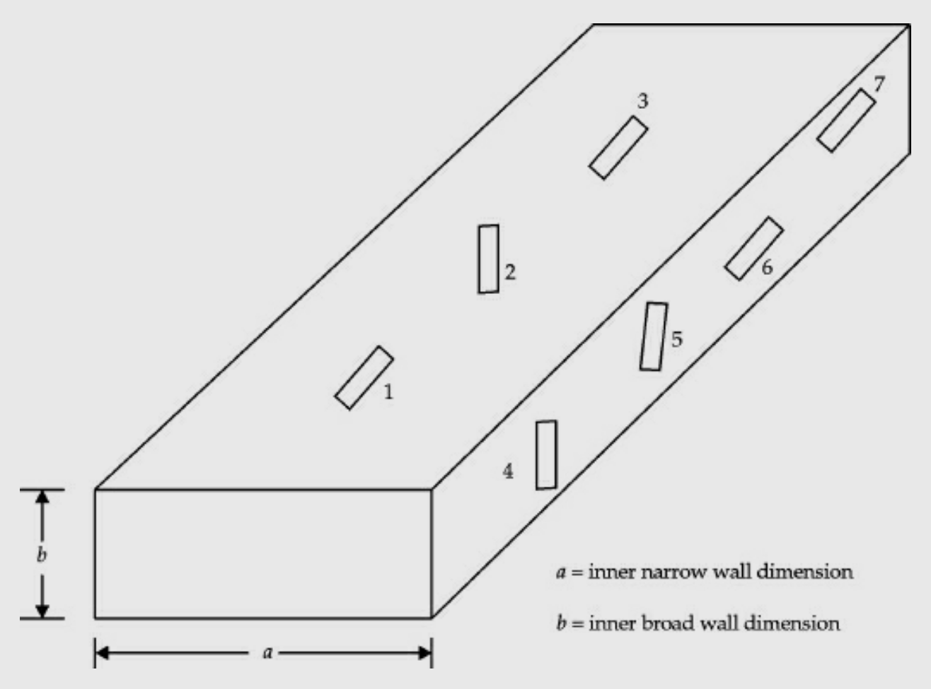
The slots can be cut in one of the walls of a rectangular waveguide. Different slot configurations are shown in Fig. Below,
The types of slots are:
Slot 1: Longitudinal slot in the centre of broad wall.
Slot 2: Inclined slot in the broad wall.
Slot 3: Displaced slot in the broad wall.
Slot 4: Vertical slot in the narrow wall of the waveguide.
Slot 5: Inclined slot in the narrow wall of the waveguide.
Slot 6: Longitudinal slot in the centre of the narrow wall of the waveguide. Slot 7: Displaced longitudinal slot in the narrow wall of the waveguide.
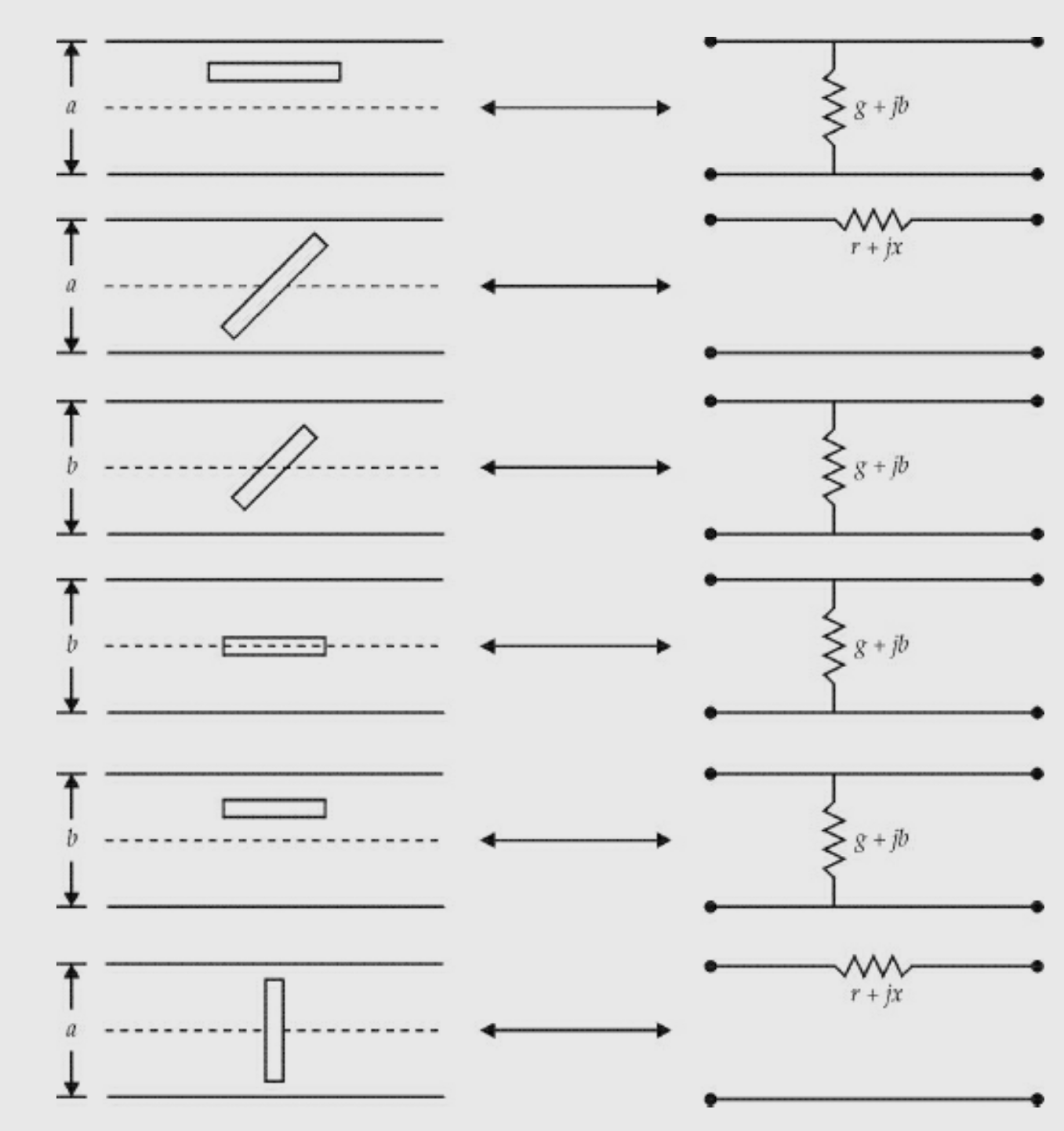
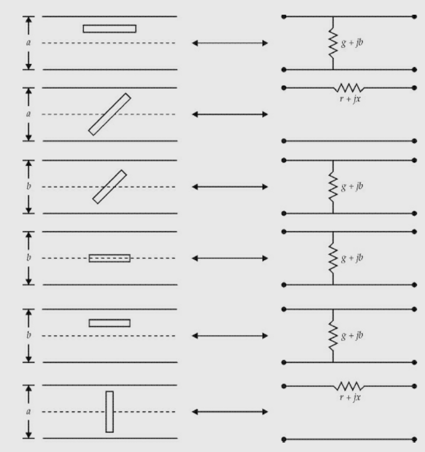
The slots 1 and 4 do not radiate and hence they are not used as radiators. But they can be used for the field or power measurements inside the guide. Slots 2, 3, 5, 6 and 7 are used as radiators. Their equivalent circuits are given in the figure below.
The theory of slots in a waveguide depends on the following assumptions:
The slots are narrow. That is, length/width >> 1.
The slot length ≈ λ/2.
The field in the slot is transverse to the long dimension. It varies sinusoidally and is independent of the exciting system.
The guide walls are perfectly conducting and infinitely thin.
The field in the region behind the face containing the slot is negligible compared to the field outside the guide.
It is a radiating element which has the shape of a horn. It is a waveguide one end of which is flared out.
A waveguide, when excited at one end and open at the second end, radiates. However, radiation is poor and non-directive pattern results because of the mismatch between the waveguide and free space. The mouth of the waveguide is flared out to improve the radiation efficiency, directive pattern and directivity.
Types of horns:
Sectoral horn
Pyramidal horn
Conical horn.
Sectoral horn is of two types:
Sectoral H-plane horn
Sectoral E-plane horn.
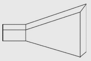
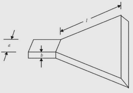
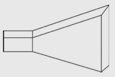
These are shown in the figures below,
Sectoral H- plane horn
Sectoral E- plane horn
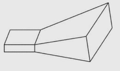
Pyramidal horn
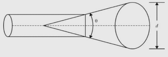
Conical horn
Sectoral horn is a horn in which flaring exists only in one direction. If flaring is along the direction of electric field, it is called sectoral E-plane horn. If flaring is along the direction of magnetic field, it is called sectoral H-plane horn.If flaring is along E and H, the horn is called pyramidal horn. It has the shape of a truncated pyramid. If the walls of a circular waveguide are flared out, a conical horn is obtained.
The horn parameters are described as shown in the figure below :
δ = path difference
l = axial length
d = aperture dimension
Ѳ = flare angle
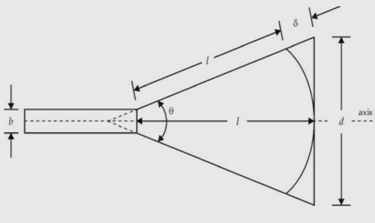
Horn parameters
Features :
Horn becomes small if the flare angle is small. Its radiation pattern is directive, wave front is spherical, mouth area is small and its directivity is small.
Flare angle is related to axial length.
If θ = 15°, when l/λ = 50, the beam width is 23° and directivity is 120. Directivity of pyramidal horn is more as the flare is in more than one direction.
Its directivity is not as high as that of paraboloid.
It is used as radiator.
It is easy to use with the waveguide.
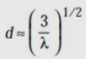
It is used as primary antenna for paraboloid. The gain of the conical antenna is optimum for a given slant length of flare, l and
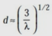
Here, d = diameter of the aperture.
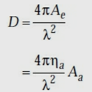
The directivity of a loss-less horn antenna is its gain and it is given by
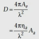
Here, Ae is effective aperture, in sq. m
Aa is actual area or physical area, in sq. m
ηa is aperture efficiency
λ is operating wavelength, in m.
In the case of rectangular horn Aa = dE dH
Here, dE is aperture size in E-plane dH is aperture size in H-plane
The rectangular horn is a pyramidal horn.
In the case of conical horn Aa = πd
Here, d is aperture diameter.
If aperture efficiency is about 0.6, D ≈ 7.5 Aa/λ .
Applications of horns :
Horns are used at microwave frequencies where moderate gains are sufficient.
They are used as feed elements.
They are often used in laboratories for the measurement of different antenna parameters.
It is the most common type of microwave antenna.
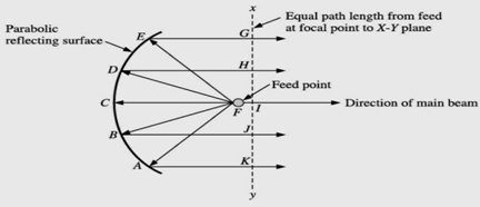
The reflector or parabolic dish consists of an antenna feed, which radiates power into a parabolic shaped reflecting surface. The parabolic reflector reflects the microwave power back along the antenna axis which is direction of beam. The parabolic dish has unique geometrical property that all rays from the feed point to any point on the parabolic surface (A or B or C or D or E) travel an equal path length from the feed point to a plane at the right angles to the direction of propagation. In the figure plane X-Y is perpendicular to the direction of beam.
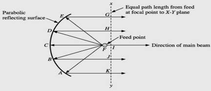
Parabolic reflector or dish antenna
In the figure feed point is F, and then the unique property of parabolic shows that FA + AK = FB + BJ = FC + CI = FD + DH = FE + EG = constant = K (say) FC = focal length of parabola K = constant which may be changed if different shape of parabola is required. The ratio of focal length to mouth diameter of a parabolic is known as the aperture of the parabolic reflector or dish antenna. Let us consider a microwave source of radiation placed at the focus F feed point. All waves coming from the source or feed will have travelled the same distance by the time they reach the plane X-Y, no matter from what point on the parabolic reflecting surface they are reflected. This is the unique geometrical property of a parabolic dish. As a result of this property, all the waves travel in phase from the X-Y plane in the direction of a beam or propagation. Thus, we get a very strong radiation towards AB axis of the parabola. It is due to this reason, it is saidthat parabolic dish produce a very strong concentrated beam of radiation.
Features :
It follows the principle of reciprocity. It means the parabolic reflector is used as both transmitting and receiving antenna. Whatever the property it exhibits while transmitting the microwave power in face space, similar property it offers in receiving the microwave power form free space. The gain, receiving area and beam width are determined by the parabolic reflector. Antenna polarisation and bandwidth are determined by the feed. It has a very sharp main lobe surrounded by a number of minor lobes, called side lobes. The three dimensional shape of the main lobe is like that of a fat cigar. The parabolic reflectors are fed by varieties of feed mechanisms. Feed could be centre feed, Cassegrain feed or offset feed.
Feed mechanism
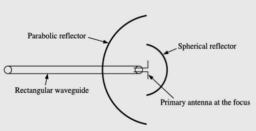
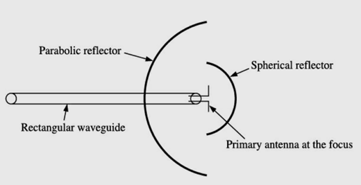
Centre feed with spherical cell: In this method, primary antenna is placed at the focus of the paraboloid to achieve best results during transmission and reception as shown in the figure,
Centre feed with spherical cell
It is to be noted that direct radiation from the feed, not reflected by the paraboloid, will spread out in all directions and loose both directivity and effective radiated power. To prevent the loss of power and directivity several method are employed. One of the methods is use of a small spherical reflector to redirect all such radiation back to the paraboloid or parabolic reflector.
Centre feed with horn antenna: This is another way of dealing with the problem of power and directivity losses. This method employs a horn antenna which points at the main parabolic reflector as shown in the figure below and directs all the microwave energy towards the parabolic reflector.
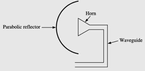
Centre feed with horn antenna
It is required to be mentioned here that the feed antenna and its reflector block certain amount of reflection from the main parabolic reflector. This blocking is minimal to the tune of 1–2%.
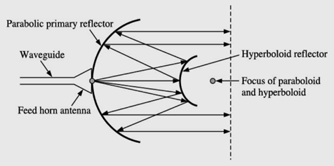
Cassegrain feed: This method of feed is named after an early eighteenth century astronomer name Cassegrain. It is illustrated in the figure below,
Cassegrain feed
It uses a hyperboloid secondary reflector. Its focus coincides with the focus of the paraboloid. The microwave power radiated from the feed horn antenna, first hits the hyperboloid and then gets reflected from the main parabolic reflector. The reflecting property of main parabolic reflector collimates (renders parallel) the radiated rays in the usual manner.
Theoretically, from a parabolic reflector, we can achieve pencil beam provided the reflecting surface is uniformly illuminated. However, this is an ideal situation which can never be achieved due to the following difficulties.
At the edge of paraboloid, the radiation beam will be diffracted considerably which creates a number of side lobes.
Surface distortions can occur in a very large dish. This problem can be mitigated by using a wide mesh rather than continuous surface.
To achieve the best results, primary feed is required to be located exactly at focus of parabolic reflector which is very difficult to achieve practically.
————————————————0————————————————-
Reference Books:
- Microwave and Radar Engineering by M.Kulkarni , Umesh Publications.
- Foundations of Microwave Engineering by R.F.Collins , McGraw Hill.
- Microwave Principles by Reich et. Al. , Van Hestrand.
- Communication in Space by Jaffen , Halt Renetal Winston.
UNIT 5
ANTENNA
An antenna is a device used for efficient radiation of electromagnetic energy (radio waves) into free space. As per the IEEE standard definitions, “an antenna is a device that converts electronic signals to electromagnetic waves and vice-versa with minimum loss of signals”.
It is the vital link to establish connectivity between transmitter and free space or free space and receiver. The purpose of transmitting antenna is to radiate maximum possible RF power (watts/kilowatts/dB)either in all directions (omni-directional antenna) or in a specified direction (directional antenna) whereas the purpose of receiving antenna is to intercept the maximum RF power which is sufficiently large compared to noise existing within receiver’s bandwidth. It is to be noted that the power received by the receiving antenna is generally of the order of microwatts and picowatts. In true sense, antennas act like transducers that transfers electromagnetic energy between transmission line and free space or antenna acts as an interface between transmission line and free space.
It is an array antenna which has structural geometry such that its impedance is periodic with the logarithm of the frequency.
It is a non-linear array in which the spacing of the elements as well as their dimensions are unequal. However, excitation is uniform. It is basically called a frequency-independent
Antenna. It can be used to receive a good number of TV channels without any 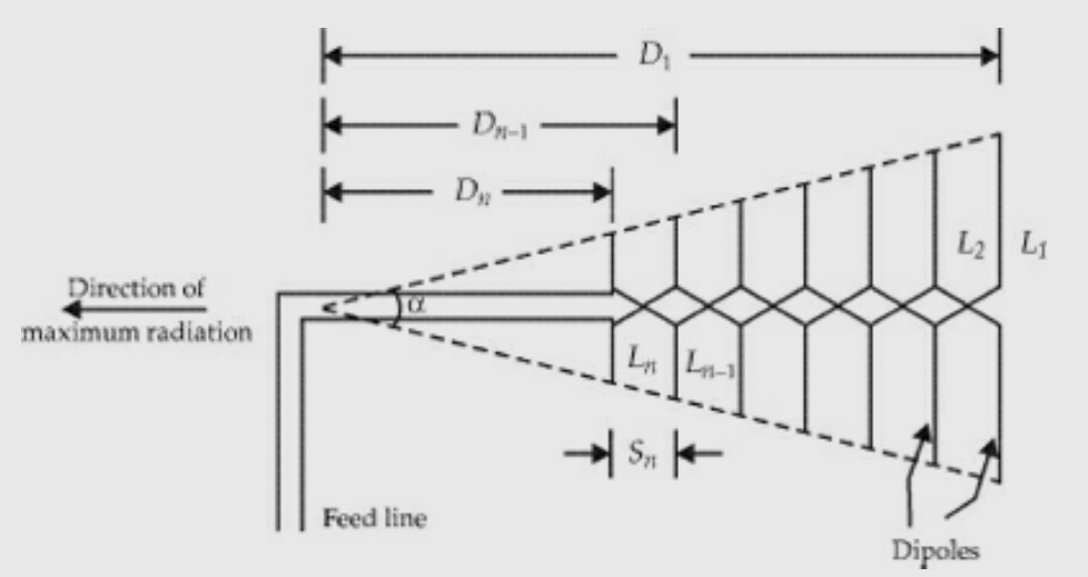
deterioration of the received field strength.
Features :
- It is a frequency-independent antenna.
- The input impedance variation of the antenna with the log of frequency is periodic and hence the name.
- It is an array of non-identical dipoles which are all excited equally.
- Is a non-uniform array where the spacing between the elements is unequal.
- Its impedance, directional patterns and directivity are constant with frequency.
- The gain of a well-designed antenna lies between 7.5 and 12 dB.
- It is a broad band antenna.
- It has uni-directional characteristics.
- There are a variety of log-periodic structures and all of them are not frequency-independent.
- They are used in VHF and UHF bands.
- They are used for TV reception and can receive a number of channels.
- The planar trapezoidal and wire trapezoidal tooth log-periodic antennas can be used.
- It is more efficient than Rhombic antenna.
The design equations are :
Where a = wedge angle or included angle =
The analysis of log-periodic array is described in terms of three regions.
Capacitive In this region, the elements are shorter than λ/2 and they are capacitive. Hence the current leads the applied voltage by 90°. These elements produce small backward radiation.
Resistive Here the dipoles are of length and they are resistive. The currents are large and they are in phase with the voltage. These elements produce considerable forward radiation.
Inductive Here elements are of length > λ/2 .The currents lag the voltage by 90°. The element reflects the incident wave in the backward direction.
It is a radiating element formed by a slot in a metallic surface. An opening cut in a conducting sheet or in one of the walls of the waveguide acts as the antenna. It is excited suitably either by a co-axial cable or through the waveguide.
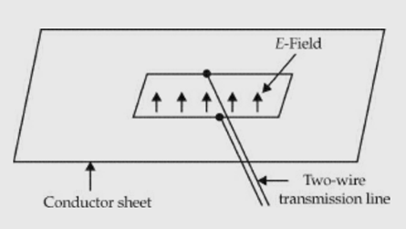
Slot antenna excited by two – wire line
Features :
- A basic slot has a length of λ/2 and its width is much less than λ/2 .
2. Slots are usually excited by a co-axial cable at a distance of about 0.05λ from one end of the slot to get reasonable impedance properties.
3. A horizontal slot with such an excitation produces vertical polarisation and vice-versa. In fact, the slot radiates from both sides.
4. If the slot is boxed with an internal dimension of λ/4 ,the radiation is outward from the opening of the box.
5. A slot and a dipole of length have similar gain and radiation characteristics. But there is a difference in polarisation.
6. In order to increase the gain and directivity, array of slots is used.
7. Cylindrical arrays of slots are found to produce omni-directional radiation in the horizontal plane with horizontal polarisation.
8. When a high frequency field exists across a thin slot in a conducting plane, it radiates.
9. A slot excited by a two-wire line. The electric field in the λ/2 slot is sinusoidal.
10. The impedance of such an excited slot is purely resistive and is 365 ohms.
A dipole and a slot in a conducting sheet have similar shapes except that the metal region and free space are interchanged.
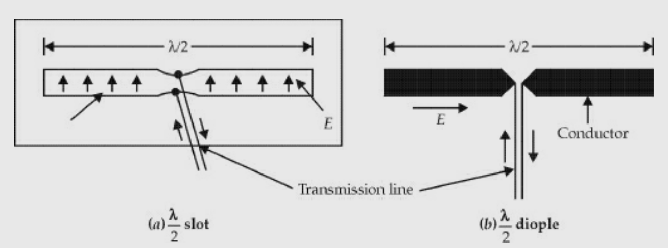
The main difference is that the slot of Fig (a) is vertically polarised and dipole of Fig.(b) is horizontally polarised.

The slot and dipole impedances are related by
Intrinsic impedance = 377 Ω
If the width of the dipole is very small, w <<λ.
Then Zd = 73 + j42.5Ω
Slot impedance, Zs =

Zs = 363 − j211 ohms
By changing the feed point from one end of the slot, its impedance can be changed. For example, two slots of different feed points are shown in Figs(a) and (b).
The slots can be cut in one of the walls of a rectangular waveguide. Different slot configurations are shown in Fig. Below,
The types of slots are:
Slot 1: Longitudinal slot in the centre of broad wall.
Slot 2: Inclined slot in the broad wall.
Slot 3: Displaced slot in the broad wall.
Slot 4: Vertical slot in the narrow wall of the waveguide.
Slot 5: Inclined slot in the narrow wall of the waveguide.
Slot 6: Longitudinal slot in the centre of the narrow wall of the waveguide. Slot 7: Displaced longitudinal slot in the narrow wall of the waveguide.
The slots 1 and 4 do not radiate and hence they are not used as radiators. But they can be used for the field or power measurements inside the guide. Slots 2, 3, 5, 6 and 7 are used as radiators. Their equivalent circuits are given in the figure below.
The theory of slots in a waveguide depends on the following assumptions:
The slots are narrow. That is, length/width >> 1.
The slot length ≈ λ/2.
The field in the slot is transverse to the long dimension. It varies sinusoidally and is independent of the exciting system.
The guide walls are perfectly conducting and infinitely thin.
The field in the region behind the face containing the slot is negligible compared to the field outside the guide.
It is a radiating element which has the shape of a horn. It is a waveguide one end of which is flared out.
A waveguide, when excited at one end and open at the second end, radiates. However, radiation is poor and non-directive pattern results because of the mismatch between the waveguide and free space. The mouth of the waveguide is flared out to improve the radiation efficiency, directive pattern and directivity.
Types of horns:
Sectoral horn
Pyramidal horn
Conical horn.
Sectoral horn is of two types:
Sectoral H-plane horn
Sectoral E-plane horn.
These are shown in the figures below,
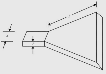
Sectoral H- plane horn
Sectoral E- plane horn
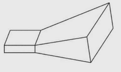
Pyramidal horn
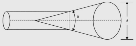
Conical horn
Sectoral horn is a horn in which flaring exists only in one direction. If flaring is along the direction of electric field, it is called sectoral E-plane horn. If flaring is along the direction of magnetic field, it is called sectoral H-plane horn.If flaring is along E and H, the horn is called pyramidal horn. It has the shape of a truncated pyramid. If the walls of a circular waveguide are flared out, a conical horn is obtained.
The horn parameters are described as shown in the figure below :
δ = path difference
l = axial length
d = aperture dimension
Ѳ = flare angle
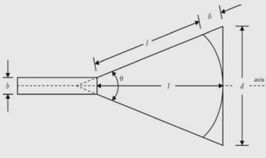
Horn parameters
Features :
Horn becomes small if the flare angle is small. Its radiation pattern is directive, wave front is spherical, mouth area is small and its directivity is small.
Flare angle is related to axial length.
If θ = 15°, when l/λ = 50, the beam width is 23° and directivity is 120. Directivity of pyramidal horn is more as the flare is in more than one direction.
Its directivity is not as high as that of paraboloid.
It is used as radiator.
It is easy to use with the waveguide.
It is used as primary antenna for paraboloid. The gain of the conical antenna is optimum for a given slant length of flare, l and
Here, d = diameter of the aperture.
The directivity of a loss-less horn antenna is its gain and it is given by
Here, Ae is effective aperture, in sq. m
Aa is actual area or physical area, in sq. m
ηa is aperture efficiency
λ is operating wavelength, in m.
In the case of rectangular horn Aa = dE dH
Here, dE is aperture size in E-plane dH is aperture size in H-plane
The rectangular horn is a pyramidal horn.
In the case of conical horn Aa = πd
Here, d is aperture diameter.
If aperture efficiency is about 0.6, D ≈ 7.5 Aa/λ .
Applications of horns :
Horns are used at microwave frequencies where moderate gains are sufficient.
They are used as feed elements.
They are often used in laboratories for the measurement of different antenna parameters.
It is the most common type of microwave antenna.
The reflector or parabolic dish consists of an antenna feed, which radiates power into a parabolic shaped reflecting surface. The parabolic reflector reflects the microwave power back along the antenna axis which is direction of beam. The parabolic dish has unique geometrical property that all rays from the feed point to any point on the parabolic surface (A or B or C or D or E) travel an equal path length from the feed point to a plane at the right angles to the direction of propagation. In the figure plane X-Y is perpendicular to the direction of beam.
Parabolic reflector or dish antenna
In the figure feed point is F, and then the unique property of parabolic shows that FA + AK = FB + BJ = FC + CI = FD + DH = FE + EG = constant = K (say) FC = focal length of parabola K = constant which may be changed if different shape of parabola is required. The ratio of focal length to mouth diameter of a parabolic is known as the aperture of the parabolic reflector or dish antenna. Let us consider a microwave source of radiation placed at the focus F feed point. All waves coming from the source or feed will have travelled the same distance by the time they reach the plane X-Y, no matter from what point on the parabolic reflecting surface they are reflected. This is the unique geometrical property of a parabolic dish. As a result of this property, all the waves travel in phase from the X-Y plane in the direction of a beam or propagation. Thus, we get a very strong radiation towards AB axis of the parabola. It is due to this reason, it is saidthat parabolic dish produce a very strong concentrated beam of radiation.
Features :
It follows the principle of reciprocity. It means the parabolic reflector is used as both transmitting and receiving antenna. Whatever the property it exhibits while transmitting the microwave power in face space, similar property it offers in receiving the microwave power form free space. The gain, receiving area and beam width are determined by the parabolic reflector. Antenna polarisation and bandwidth are determined by the feed. It has a very sharp main lobe surrounded by a number of minor lobes, called side lobes. The three dimensional shape of the main lobe is like that of a fat cigar. The parabolic reflectors are fed by varieties of feed mechanisms. Feed could be centre feed, Cassegrain feed or offset feed.
Feed mechanism
Centre feed with spherical cell: In this method, primary antenna is placed at the focus of the paraboloid to achieve best results during transmission and reception as shown in the figure,
Centre feed with spherical cell
It is to be noted that direct radiation from the feed, not reflected by the paraboloid, will spread out in all directions and loose both directivity and effective radiated power. To prevent the loss of power and directivity several method are employed. One of the methods is use of a small spherical reflector to redirect all such radiation back to the paraboloid or parabolic reflector.
Centre feed with horn antenna: This is another way of dealing with the problem of power and directivity losses. This method employs a horn antenna which points at the main parabolic reflector as shown in the figure below and directs all the microwave energy towards the parabolic reflector.
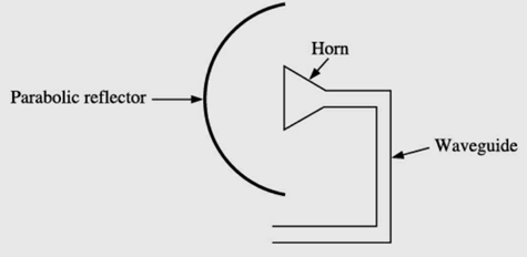
Centre feed with horn antenna
It is required to be mentioned here that the feed antenna and its reflector block certain amount of reflection from the main parabolic reflector. This blocking is minimal to the tune of 1–2%.
Cassegrain feed: This method of feed is named after an early eighteenth century astronomer name Cassegrain. It is illustrated in the figure below,
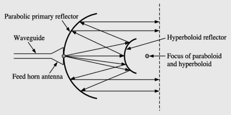
Cassegrain feed
It uses a hyperboloid secondary reflector. Its focus coincides with the focus of the paraboloid. The microwave power radiated from the feed horn antenna, first hits the hyperboloid and then gets reflected from the main parabolic reflector. The reflecting property of main parabolic reflector collimates (renders parallel) the radiated rays in the usual manner.
Theoretically, from a parabolic reflector, we can achieve pencil beam provided the reflecting surface is uniformly illuminated. However, this is an ideal situation which can never be achieved due to the following difficulties.
At the edge of paraboloid, the radiation beam will be diffracted considerably which creates a number of side lobes.
Surface distortions can occur in a very large dish. This problem can be mitigated by using a wide mesh rather than continuous surface.
To achieve the best results, primary feed is required to be located exactly at focus of parabolic reflector which is very difficult to achieve practically.
————————————————0————————————————-
Reference Books:
- Microwave and Radar Engineering by M.Kulkarni , Umesh Publications.
- Foundations of Microwave Engineering by R.F.Collins , McGraw Hill.
- Microwave Principles by Reich et. Al. , Van Hestrand.
- Communication in Space by Jaffen , Halt Renetal Winston.