UNIT 6
MICROWAVE LINKS & SPACE COMMUNICATION
A satellite is a physical object which revolves around earth at known orbit or height. A satellite system basically consists of a satellite in space and many earth stations on the ground which are linked with each other through the satellite.
Geostationary or geosynchronous satellites orbit around the equator in a circular pattern with an angular velocity equal to that of the earth. They travel in the same direction as the earths rotation.
Since the satellite revolves with the earths rotation, it appears fixed or stationary to an observer on earth. Therefore such satellites are known as geostationary or geosynchronous satellites.
For a geostationary satellite, the angular velocity ‘ v ‘, is given by,

Where, r = average radius of earth = 6371 km
g = gravitational acceleration = 9.81 m / sec
h = height of satellite above ground
Advantages :
Keeping track is easy as the satellite remains almost stationary in respect to a given earth station.
Continuous communication is possible by one satellite only.
Coverage area of the earth is more because of the large height of the satellite.
Effect of Doppler shift frequency is negligible.
Disadvantages:
Altitude of the satellite is high, so propagation time for signal is much longer.
Signal has to travel longer distances, therefore greater path loss and attenuation takes place.
Satellite launching mechanism must be accurate and precision is required for launching such satellites at such altitudes.
Applications:
Television broadcasting
Global communications
Telephone and data circuits
Mobile telephone service
Military applications
The uplink of a satellite circuit is the one in which the earth station is transmitting the signal and the satellite is receiving it.
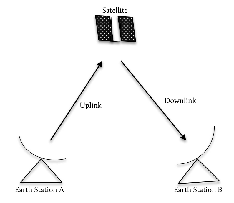
The downlink of a satellite circuit is the one in which the satellite is trans- mitting the signal and the earth station is receiving it.
A satellite link consists of an uplink (transmit earth station to satellite) and a downlink (satellite to the receive earth station); see figure. Signal quality over the uplink depends on how strong the signal is when it leaves the source earth station and how the satellite receives it. Also, on the downlink side, the signal quality depends on how strongly the satellite can retransmit the signal and how the receiving earth station receives the signal.
Satellite link design involves a mathematical approach to the selection of link subsystem variables in such a way that the overall system performance criteria are met. The most important performance criterion is the signal qual- ity, that is, the energy per bit noise density ratio ( Eb/N0 ) in the information channel, which carries the signal in the form in which it is delivered to the user. As such, in designing a satellite communication system, the designer must attempt to ensure a minimum in the receiver’s baseband chan- nels, which also meets constraints on satellite transmitter power and radio- frequency (RF) bandwidth.
The link equations deal with the calculation of the available C/N over a satellite link. The calculation of the power an earth terminal receives from a satellite transmitter is fundamental to understanding satellite communica- tions and the development of the link equations.
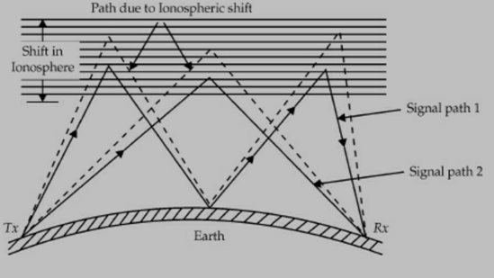
Fading is the change in signal strength at the receiver. Most of the receivers are designed with an automatic volume control (AVC) circuit which reduces the effect of fading if the change in signal strength is small. Fading up to 20 dB is common. The main causes of fading are: Variation in ionospheric conditions and Multi path reception. As the ionosphere is not stable and electron density changes, signal path length changes and hence there will be a change in phase. This causes the received field strength to change.
Fading
Fading is classified in terms of the duration of the variation in signal strength.
They are:
Rapid fluctuations : These are due to multi-path interference and they occur for a few seconds.
Short-term fluctuations : These are due to variation in the characteristics of the propagating medium and they occur for a few hours.
Long-term fluctuations : These are due to seasonal variations in the propagation medium and they occur for a few days.
Fade out (total fading) occurs during sudden ionospheric disturbances, ionospheric storms, sun spot cycle and so on.
Types of fading are:
Selective fading
Interference fading
Absorption fading
Polarisation fading
Skip fading
The features of these fadings are given below :
Selective fading: It produces serious distortion of modulated signal. It is more prominent at high frequencies at which sky-wave propagation is used. It is large with AM signals at high percentage of modulation. AM signals are more distorted by selective fading than SSB signals. Selective fading can be reduced by the use of SSB system.
Interference fading: It is produced by the interference between rays. It is also produced by the interference between waves reaching the receiver by different paths. It is also produced by the interference between a ground wave and sky wave. It occurs due to fluctuations of layer height at a fixed frequency. As the path length of the wave varies, the relative phase of waves reaching the receiver also varies. Interference fading can be minimised by different diversity techniques.
Absorption fading: This takes place due to absorption of waves by the ionosphere.
Polarisation fading: This takes place due to change of polarisation of EM wave. This is caused by cross-polarised waves. When polarisation changes, the signal amplitude changes in the receiver. This type of fading is reduced by polarisation diversity.
Skip fading: This occurs near the skip distance. The variation of height of density of the layer causes skip fading.This is minimised by AVC and AGC in the receiver.
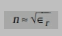
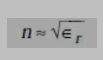
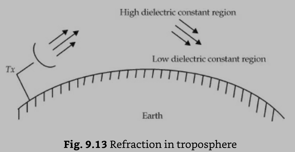
The atmosphere consists of gas molecules and water vapour. This causes the dielectric constant to be slightly greater than unity. The density of air and water vapour vary with height. As a result, the dielectric constant and hence refractive index of air depends on the height. Dielectric constant decreases withheight. The variation of refractive index with height gives rise to different phenomena like refraction, reflection, scattering, duct propagation and fading. By definition, the refractive index, n is the square root of the dielectric constant.
The phenomenon of refraction in the troposphere due to change in refractive index is shown in the figure below
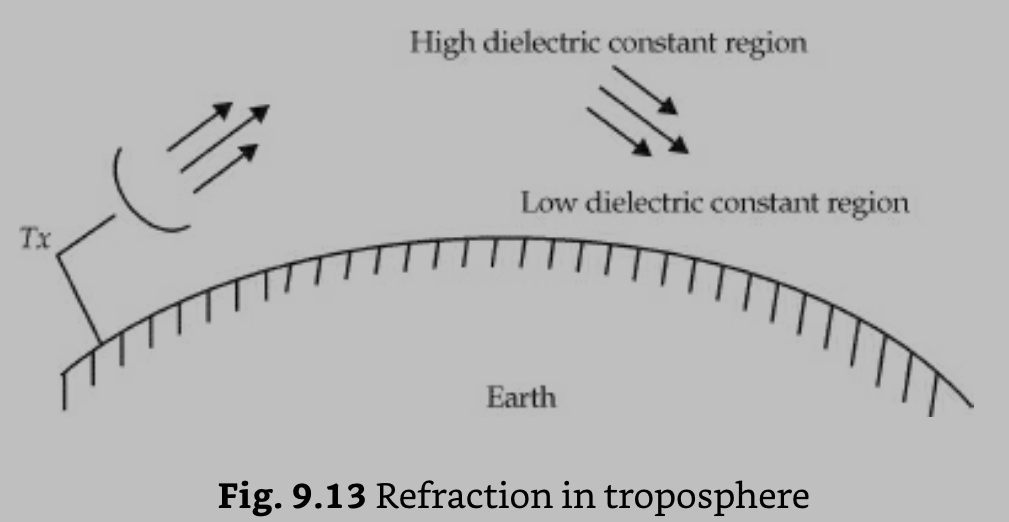
The temperature inversion zone creates super refraction or duct phenomenon as shown in the figure below. The EM rays bend away from one region to another 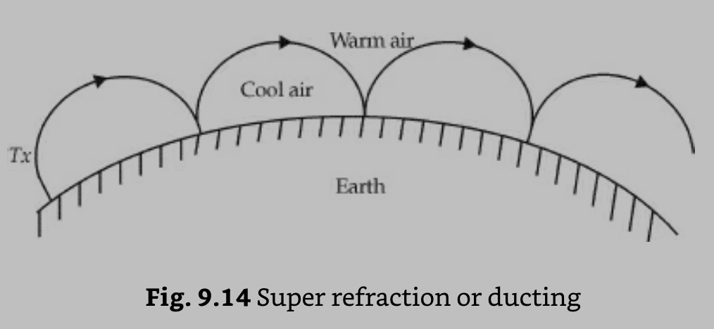 region due to change in refractive index with height.
The normal variation in the characteristics of the ionosphere occur due to the following:
Diurnal
Seasonal
Thickness and
Height variations of the ionospheric layers.
The abnormal variations in the characteristics of the ionosphere occur mainly due to changes in solar activity. The common abnormal variations are:
Ionospheric storms
Sudden ionospheric disturbances
Sunspot cycle
Fading
Whistlers
Tides and winds.
Ionospheric storms : These are due to the high absorption of sky waves and abnormal changes at the critical frequencies of E and F2 layers. These storms usually persist for a few days.
Sudden ionospheric disturbances ( SID ) : The sudden appearance of solar flares causes SIDs. The solar flares occur suddenly and sporadically. These occur during solar peak activity. SIDs block out the signals completely. They persist for a few minutes to an hour. SID causes complete fading and it is called Dellinger fade-out. Ultraviolet radiation is intensive due to solar flares in D-Layer. SID does not occur in the layer of low air density and hence it is not found in E, Fl and F2 layers.
Sun spot cycle : Sun spot cycle is a eleven years cycle during which radiation varies drastically. The variation due to ultraviolet rays, flares, particle radiation and sun spots is very high and it is low due to light. During sun spot maxima, the critical frequencies arethe highest and they are lowest during sun spot minima. To minimise the effect of sun spot cycle, the operating frequency is carefully chosen.
Whistlers : Whistlers are the transient electromagnetic disturbances which occur naturally. Whistlers consist of EM pulses of audio frequency radiation along the direction of the magnetic field of the earth between conjugate points in the northern and southern hemispheres. Long whistlers, short whistlers and noise whistlers are a few types of whistlers. The composition of the upper atmosphere can be provided by whistlers.
Tides and winds : Tides and winds are common in the atmosphere. Solar tide effects are more pronounced. The winds in the ionosphere are caused by the tides. The presence of ionospheric winds are due to the motion of turbulence in F2-layer. Tidal effect introduces a small peak of maximum ionisation density in the layer at mid-night.
—————————————0——————————————
Reference Books:
- Microwave and Radar Engineering by M.Kulkarni , Umesh Publications.
- Foundations of Microwave Engineering by R.F.Collins , McGraw Hill.
- Microwave Principles by Reich et. Al. , Van Hestrand.
Communication in Space by Jaffen , Halt Renetal Winston
UNIT 6
MICROWAVE LINKS & SPACE COMMUNICATION
A satellite is a physical object which revolves around earth at known orbit or height. A satellite system basically consists of a satellite in space and many earth stations on the ground which are linked with each other through the satellite.
Geostationary or geosynchronous satellites orbit around the equator in a circular pattern with an angular velocity equal to that of the earth. They travel in the same direction as the earths rotation.
Since the satellite revolves with the earths rotation, it appears fixed or stationary to an observer on earth. Therefore such satellites are known as geostationary or geosynchronous satellites.
For a geostationary satellite, the angular velocity ‘ v ‘, is given by,

Where, r = average radius of earth = 6371 km
g = gravitational acceleration = 9.81 m / sec
h = height of satellite above ground
Advantages :
Keeping track is easy as the satellite remains almost stationary in respect to a given earth station.
Continuous communication is possible by one satellite only.
Coverage area of the earth is more because of the large height of the satellite.
Effect of Doppler shift frequency is negligible.
Disadvantages:
Altitude of the satellite is high, so propagation time for signal is much longer.
Signal has to travel longer distances, therefore greater path loss and attenuation takes place.
Satellite launching mechanism must be accurate and precision is required for launching such satellites at such altitudes.
Applications:
Television broadcasting
Global communications
Telephone and data circuits
Mobile telephone service
Military applications
The uplink of a satellite circuit is the one in which the earth station is transmitting the signal and the satellite is receiving it.
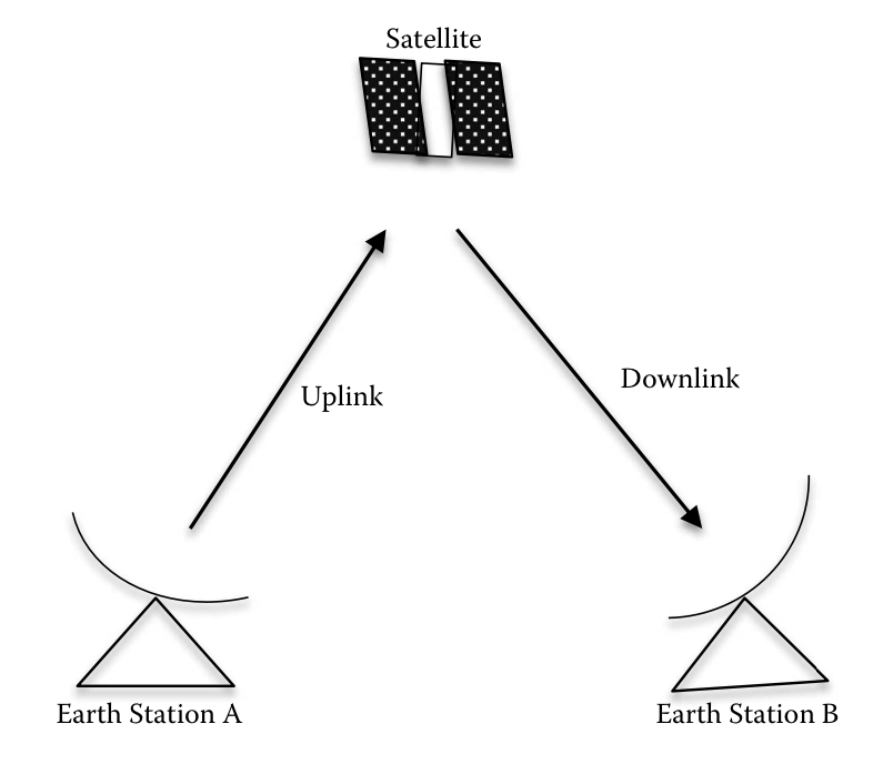
The downlink of a satellite circuit is the one in which the satellite is trans- mitting the signal and the earth station is receiving it.
A satellite link consists of an uplink (transmit earth station to satellite) and a downlink (satellite to the receive earth station); see figure. Signal quality over the uplink depends on how strong the signal is when it leaves the source earth station and how the satellite receives it. Also, on the downlink side, the signal quality depends on how strongly the satellite can retransmit the signal and how the receiving earth station receives the signal.
Satellite link design involves a mathematical approach to the selection of link subsystem variables in such a way that the overall system performance criteria are met. The most important performance criterion is the signal qual- ity, that is, the energy per bit noise density ratio ( Eb/N0 ) in the information channel, which carries the signal in the form in which it is delivered to the user. As such, in designing a satellite communication system, the designer must attempt to ensure a minimum in the receiver’s baseband chan- nels, which also meets constraints on satellite transmitter power and radio- frequency (RF) bandwidth.
The link equations deal with the calculation of the available C/N over a satellite link. The calculation of the power an earth terminal receives from a satellite transmitter is fundamental to understanding satellite communica- tions and the development of the link equations.
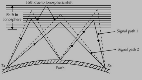
Fading is the change in signal strength at the receiver. Most of the receivers are designed with an automatic volume control (AVC) circuit which reduces the effect of fading if the change in signal strength is small. Fading up to 20 dB is common. The main causes of fading are: Variation in ionospheric conditions and Multi path reception. As the ionosphere is not stable and electron density changes, signal path length changes and hence there will be a change in phase. This causes the received field strength to change.
Fading
Fading is classified in terms of the duration of the variation in signal strength.
They are:
Rapid fluctuations : These are due to multi-path interference and they occur for a few seconds.
Short-term fluctuations : These are due to variation in the characteristics of the propagating medium and they occur for a few hours.
Long-term fluctuations : These are due to seasonal variations in the propagation medium and they occur for a few days.
Fade out (total fading) occurs during sudden ionospheric disturbances, ionospheric storms, sun spot cycle and so on.
Types of fading are:
Selective fading
Interference fading
Absorption fading
Polarisation fading
Skip fading
The features of these fadings are given below :
Selective fading: It produces serious distortion of modulated signal. It is more prominent at high frequencies at which sky-wave propagation is used. It is large with AM signals at high percentage of modulation. AM signals are more distorted by selective fading than SSB signals. Selective fading can be reduced by the use of SSB system.
Interference fading: It is produced by the interference between rays. It is also produced by the interference between waves reaching the receiver by different paths. It is also produced by the interference between a ground wave and sky wave. It occurs due to fluctuations of layer height at a fixed frequency. As the path length of the wave varies, the relative phase of waves reaching the receiver also varies. Interference fading can be minimised by different diversity techniques.
Absorption fading: This takes place due to absorption of waves by the ionosphere.
Polarisation fading: This takes place due to change of polarisation of EM wave. This is caused by cross-polarised waves. When polarisation changes, the signal amplitude changes in the receiver. This type of fading is reduced by polarisation diversity.
Skip fading: This occurs near the skip distance. The variation of height of density of the layer causes skip fading.This is minimised by AVC and AGC in the receiver.
The atmosphere consists of gas molecules and water vapour. This causes the dielectric constant to be slightly greater than unity. The density of air and water vapour vary with height. As a result, the dielectric constant and hence refractive index of air depends on the height. Dielectric constant decreases withheight. The variation of refractive index with height gives rise to different phenomena like refraction, reflection, scattering, duct propagation and fading. By definition, the refractive index, n is the square root of the dielectric constant.
The phenomenon of refraction in the troposphere due to change in refractive index is shown in the figure below
The temperature inversion zone creates super refraction or duct phenomenon as shown in the figure below. The EM rays bend away from one region to another 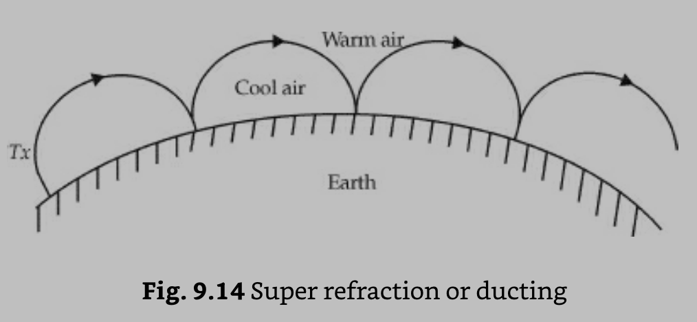 region due to change in refractive index with height.
The normal variation in the characteristics of the ionosphere occur due to the following:
Diurnal
Seasonal
Thickness and
Height variations of the ionospheric layers.
The abnormal variations in the characteristics of the ionosphere occur mainly due to changes in solar activity. The common abnormal variations are:
Ionospheric storms
Sudden ionospheric disturbances
Sunspot cycle
Fading
Whistlers
Tides and winds.
Ionospheric storms : These are due to the high absorption of sky waves and abnormal changes at the critical frequencies of E and F2 layers. These storms usually persist for a few days.
Sudden ionospheric disturbances ( SID ) : The sudden appearance of solar flares causes SIDs. The solar flares occur suddenly and sporadically. These occur during solar peak activity. SIDs block out the signals completely. They persist for a few minutes to an hour. SID causes complete fading and it is called Dellinger fade-out. Ultraviolet radiation is intensive due to solar flares in D-Layer. SID does not occur in the layer of low air density and hence it is not found in E, Fl and F2 layers.
Sun spot cycle : Sun spot cycle is a eleven years cycle during which radiation varies drastically. The variation due to ultraviolet rays, flares, particle radiation and sun spots is very high and it is low due to light. During sun spot maxima, the critical frequencies arethe highest and they are lowest during sun spot minima. To minimise the effect of sun spot cycle, the operating frequency is carefully chosen.
Whistlers : Whistlers are the transient electromagnetic disturbances which occur naturally. Whistlers consist of EM pulses of audio frequency radiation along the direction of the magnetic field of the earth between conjugate points in the northern and southern hemispheres. Long whistlers, short whistlers and noise whistlers are a few types of whistlers. The composition of the upper atmosphere can be provided by whistlers.
Tides and winds : Tides and winds are common in the atmosphere. Solar tide effects are more pronounced. The winds in the ionosphere are caused by the tides. The presence of ionospheric winds are due to the motion of turbulence in F2-layer. Tidal effect introduces a small peak of maximum ionisation density in the layer at mid-night.
—————————————0——————————————
Reference Books:
- Microwave and Radar Engineering by M.Kulkarni , Umesh Publications.
- Foundations of Microwave Engineering by R.F.Collins , McGraw Hill.
- Microwave Principles by Reich et. Al. , Van Hestrand.
Communication in Space by Jaffen , Halt Renetal Winston