UNIT 1
DATA COMMUNICATION COMPONENTS
Data Representation refers to the form in which data is stored, processed, and transmitted.
Devices such as smartphones, iPods, and computers store data in digital formats that can be handled by electronic circuitry.
Digitization is the process of converting information, such as text, numbers, photo, or music, into digital data that can be manipulated by electronic devices. • The Digital Revolution has evolved through four phases, beginning with big, expensive, standalone computers, and progressing to today’s digital world in which small, inexpensive digital devices are everywhere.
The 0s and 1s used to represent digital data are referred to as binary digits — from this term we get the word bit that stands for binary digit. • A bit is a 0 or 1 used in the digital representation of data. • A digital file, usually referred to simply as a file, is a named collection of data that exits on a storage medium, such as a hard disk, CD, DVD, or flash drive.
Types of Network Topology
a) Mesh Topology
In mesh topology, every device is connected to another device via particular channel.
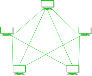
- Every device is connected with another via dedicated channels. These channels are known as links.
If suppose, N number of devices are connected with each other in mesh topology, then total number of ports that is required by each device is? N-1. In the Figure 1, there are 5 devices connected to each other, hence total number of ports required is 4. - If suppose, N number of devices are connected with each other in mesh topology, then total number of dedicated links required to connect them is NC2 i.e. N(N-1)/2. In the Figure 1, there are 5 devices connected to each other, hence total number of links required is 5*4/2 = 10.
b) Star Topology:
In star topology, all the devices are connected to a single hub through a cable. This hub is the central node and all others nodes are connected to the central node. The hub can be passive in nature i.e. not intelligent hub such as broadcasting devices, at the same time the hub can be intelligent known as active hubs. Active hubs have repeaters in them.
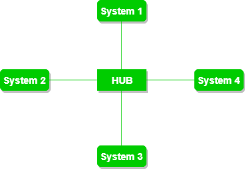
A star topology having four systems connected to single point of connection i.e. hub.
c) Bus Topology:
Bus topology is a network type in which every computer and network device is connected to single cable. It transmits the data from one end to another in single direction. No bi-directional feature is in bus topology.
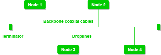
A bus topology with shared backbone cable. The nodes are connected to the channel via drop lines.
d) Ring Topology:
In this topology, it forms a ring connecting devices with its exactly two neighbouring devices.
A number of repeaters are used for Ring topology with a large number of nodes, because if someone wants to send some data to the last node in the ring topology with 100 nodes, then the data will have to pass through 99 nodes to reach the 100th node. Hence to prevent data loss repeaters are used in the network.
The transmission is unidirectional, but it can be made bidirectional by having 2 connections between each Network Node, it is called Dual Ring Topology.
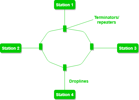
A ring topology comprises of 4 stations connected with each forming a ring.
Operations take place in ring topology are:
- One station is known as monitor station which takes all the responsibility to perform the operations.
- To transmit the data, station has to hold the token. After the transmission is done, the token is to be released for other stations to use.
- When no station is transmitting the data, then the token will circulate in the ring.
- There are two types of token release techniques: Early token release releases the token just after the transmitting the data and Delay token release releases the token after the acknowledgement is received from the receiver.
e) Tree Topology:
This topology is the variation of Star topology. This topology has hierarchical flow of data.
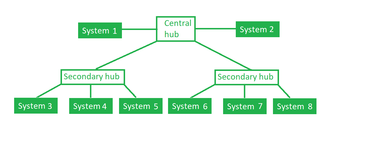
In this the various secondary hubs are connected to the central hub which contains the repeater. In this data flow from top to bottom i.e. from the central hub to secondary and then to the devices or from bottom to top i.e. devices to secondary hub and then to the central hub.
There are various categories of protocols like routing protocols, mail transferring protocols, remote communication protocols, and many more. Network security protocols are one such category that makes sure that the security and integrity of the data are preserved over a network. Various methodologies, techniques, and processes are involved in these protocols to secure the network data from any illegitimate attempt in reviewing or extracting the actual content of data.
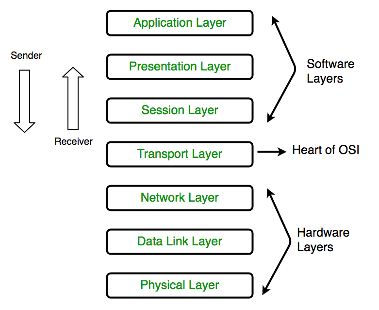
The OSI Model (Open Systems Interconnection Model) is a conceptual framework used to describe the functions of a networking system. The OSI model characterizes computing functions into a universal set of rules and requirements in order to support interoperability between different products and software.
The 7 Layers of the OSI Model
Physical Layer
The lowest layer of the OSI Model is concerned with electrically or optically transmitting raw unstructured data bits across the network from the physical layer of the sending device to the physical layer of the receiving device. It can include specifications such as voltages, pin layout, cabling, and radio frequencies. At the physical layer, one might find “physical” resources such as network hubs, cabling, repeaters, network adapters or modems.
Data Link Layer
At the data link layer, directly connected nodes are used to perform node-to-node data transfer where data is packaged into frames. The data link layer also corrects errors that may have occurred at the physical layer.
The data link layer encompasses two sub-layers of its own. The first, media access control (MAC), provides flow control and multiplexing for device transmissions over a network. The second, the logical link control (LLC), provides flow and error control over the physical medium as well as identifies line protocols.
Network Layer
The network layer is responsible for receiving frames from the data link layer, and delivering them to their intended destinations among based on the addresses contained inside the frame. The network layer finds the destination by using logical addresses, such as IP (internet protocol). At this layer, routers are a crucial component used to quite literally route information where it needs to go between networks.
Transport Layer
The transport layer manages the delivery and error checking of data packets. It regulates the size, sequencing, and ultimately the transfer of data between systems and hosts. One of the most common examples of the transport layer is TCP or the Transmission Control Protocol.
Session Layer
The session layer controls the conversations between different computers. A session or connection between machines is set up, managed, and termined at layer 5. Session layer services also include authentication and reconnections.
Presentation Layer
The presentation layer formats or translates data for the application layer based on the syntax or semantics that the application accepts. Because of this, it at times also called the syntax layer. This layer can also handle the encryption and decryption required by the application layer.
Application Layer
At this layer, both the end user and the application layer interact directly with the software application. This layer sees network services provided to end-user applications such as a web browser or Office 365. The application layer identifies communication partners, resource availability, and synchronizes communication.
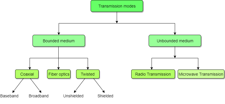
Data is represented by computers and other telecommunication devices using signals. Signals are transmitted in the form of electromagnetic energy from one device to another. Electromagnetic signals travel through vacuum, air or other transmission mediums to move from one point to another (from sender to receiver).
Electromagnetic energy (includes electrical and magnetic fields) consists of power, voice, visible light, radio waves, ultraviolet light, gamma rays etc.
Transmission medium is the means through which we send our data from one place to another. The first layer (physical layer) of Communication Networks OSI Seven-layer model is dedicated to the transmission media, we will study the OSI Model later.
- A local area network (LAN) is a collection of devices connected together in one physical location, such as a building, office, or home. A LAN can be small or large, ranging from a home network with one user to an enterprise network with thousands of users and devices in an office or school.
- A LAN comprises cables, access points, switches, routers, and other components that enable devices to connect to internal servers, web servers, and other LANs via wide area networks.
- The advantages of a LAN are the same as those for any group of devices networked together. The devices can use a single Internet connection, share files with one another, print to shared printers, and be accessed and even controlled by one another.
- A WLAN, or wireless LAN, is a network that allows devices to connect and communicate wirelessly. Unlike a traditional wired LAN, in which devices communicate over Ethernet cables, devices on a WLAN communicate via Wi-Fi.
- A wireless LAN (WLAN) is a wireless computer network that links two or more devices using wireless communication to form a local area network (LAN) within a limited area such as a home, school, computer laboratory, campus, or office building. This gives users the ability to move around within the area and remain connected to the network. Through a gateway, a WLAN can also provide a connection to the wider Internet.
- LAN stands for Local Area Network is a group of network devices which allow the communication between connected devices. On the other hand VLAN stands for Virtual Local Area Network which is used to enhance the performance of LANs (Local Area Networks).
- Virtual LAN (VLAN) is any broadcast domain that is partitioned and isolated in a computer network at the data link layer (OSI layer 2). LAN is the abbreviation for local area network and in this context virtual refers to a physical object recreated and altered by additional logic.
- Bandwidth utilization is the wise use of available bandwidth to achieve specific goals specific goals. Efficiency can be achieved by Efficiency can be achieved by multiplexing; privacy and anti-jamming can be achieved by spreading.
Whenever the bandwidth of a medium linking two devices is greater than the bandwidth needs of the devices, devices, the link can be shared. Multiplexing the set of techniques that allows the simultaneous transmission of multiple signals across a single data link.
1. Frequency Division Multiplexing (FDM) –
In this a number of signals are transmitted at the same time, and each source transfers its signals in the allotted frequency range. There is a suitable frequency gap between the 2 adjacent signals to avoid over-lapping. Since the signals are transmitted in allotted time so this decreases the probability of collision. The frequency spectrum is divided into several logical channels, in which every user feels that they possess a particular bandwidth. A number of signals are sent simultaneously on the same time allocating separate frequency band or channel to each signal. It is used in radio and TV transmission. Therefore, to avoid interference between two successive channels Guard bands are used.

2. Time Division Multiplexing (TDM) –
This happens when data transmission rate of media is greater than that of the source, and each signal is allotted a definite amount of time. These slots are so small that all transmissions appear to be parallel. In frequency division multiplexing all the signals operate at the same time with different frequencies, but in time division multiplexing all the signals operate with same frequency at different times.
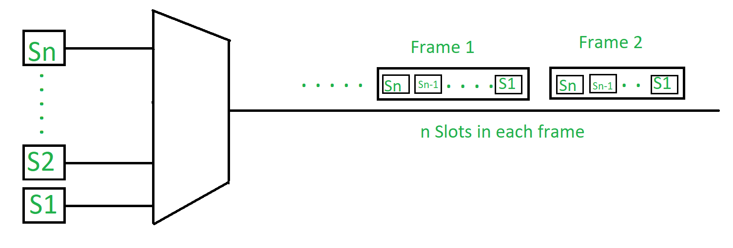
It is of following types:
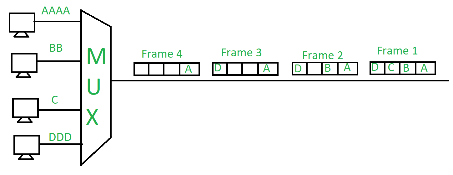
- Synchronous TDM –
The time slots are pre-assigned and fixed. This slot is even given if the source is not ready with data at this time. In this case the slot is transmitted empty. It is used for multiplexing digitized voice stream.
2. Asynchronous (or statistical) TDM –
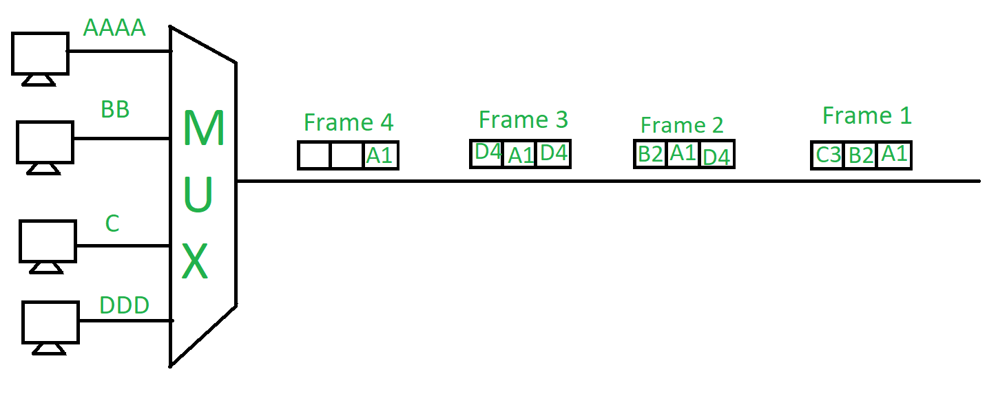
The slots are allocated dynamically depending on the speed of source or their ready state. It dynamically allocates the time slots according to different input channel’s needs, thus saving the channel capacity.
WDM
Wavelength division multiplexing (WDM) is a technology or technique modulating numerous data streams, i.e. optical carrier signals of varying wavelengths (colours) of laser light, onto a single optical fibre. WDM enables bi-directional communication as well as multiplication of signal capacity.
WDM is actually frequency division multiplexing (FDM) but referencing the wavelength of light as opposed to the frequency of light. However, since wavelength and frequency have an inverse relationship (shorter wavelength means higher frequency), the WDM and FDM terms actually describe the same technology – light in optical cable used to carry data and communication signals.
Spread Spectrum
Spread spectrum is a form of wireless communications in which the frequency of the transmitted signal is deliberately varied. This results in a much greater bandwidth than the signal would have if its frequency were not varied.
A conventional wireless signal has a frequency, usually specified in megahertz (MHz) or gigahertz gigahertz), that does not change with time (except for small, rapid fluctuations that occur as a result of modulation). When you listen to a signal at 103.1 MHz on an FM stereo receiver, for example, the signal stays at 103.1 MHz It does not go up to 105.1 MHz or down to 99.1 MHz. The digits on the radio's frequency dial stay the same at all times. The frequency of a conventional wireless signal is kept as constant as the state of the art will permit, so the bandwidth can be kept within certain limits, and so the signal can be easily located by someone who wants to retrieve the information.