Unit 1
Control System
A control system is a set of mechanical or electronic devices which control the other devices. In control system behaviours of the system is desired by differential equations.
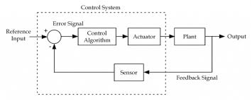
The above figure shows a feedback system with a control system. The components of control system are:
i) The actuator takes the signal transforms it accordingly and causes some action.
Ii) Sensors are used to measure continuous and discrete process variables.
Iii) Controllers are those elements which adjust the actuators in response to the measurement.
a) Open Loop control System:-
This is the loop of control system without any feedback. In this the control action is not dependent on the desired output.
 Fig. 1 open loop control system
Example of open Loop systems are The traffic signals, Automatic washing machine and in fields control d.c motor.
b) Closed Loop control system:-
This is a type of control system with feedback .In this type of system The control action is dependent on the desired output.
c) Feedforward System:-
The feedback system are which work to reduce the error it’s the system. In some system where the disturbances input can be provided beforehand , its effect can be eliminated by feedforward system .
d) Tracking System :-
The main objective of such system is to trace any particular location as direction of a target value on continuous basic. The basic examples of tracking, Range tracking, Tracking in phased array radars.
e) Regulator System:-The main objective of suchsystems is to maintain a designated characteristic they try to maintain a range of values is a machine for ex. Voltage regulator etc.
 Fig 2. Closed Loop control system
The error signal is again fed to controller to the error and get desired output.
Comparisons between open Loop and Closed Loop system
Open Loop System | Closed Loop system |
1.It does Not have any feedback. | 1. This system comprise of feedback |
2.As no feedback so easier to build. | 2.As it has feedback so difficult to build |
3.Theaccuracy of this system depends on the calibration of input. | 3.They are accuracy because of the feedback. |
4.Open Loop systems are more stable. | 4.In closed Loop system stability depends on system components. |
5.optimization is not possible | 5. Optimization is possible |
6.These systems are not reliable. | They are more reliable |
Advt. Of Block diagram reduction technique:
(1) Very simple to Construct the Block diagram of complicated electrical & mechanical sys.
(2) The function of individual element can be visualized form block diagram
(3) Individual as well as over all performance of the system can be studied by the if shown in Block diag.
(4) Overall CLTf can be easily calculated by Block diag reduction rules.
Disadvantage:-
(1) It doesnot include any information above physical construct of system (completely mathematical approach).
a) Source of energy is generally not shown in the block diagram. So we get different block diagram can be drawn for the same function
CLTf:--ve feedback
C(s)/R(s)= G(s)/1+G(s)H(s)
CLTF:-+vefeedback
C(S)/R(S) = G(S)/1-G(s)H(S)
SIGNAL FLOW GRAPH :- (SFG)


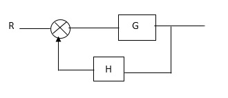
Block Diagram

SFG
Q:-
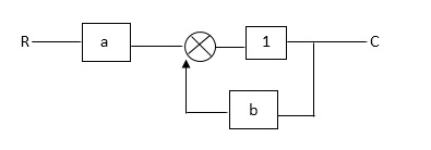
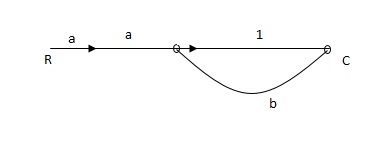
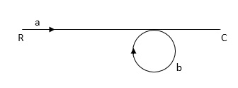
Ra+cb =c
c/R= a/1-b
Diagram:-
RULES:-
1) Thesignal travels along a branch in the direction of an arrow.
2) The lip signal is multiplied by the transmittance to obtain the o/p.
3) I/p signal at a node is sum of all the signals entering at that node .
4) A node transmits signal at all branches leaving that node.
Q. The SFG shown has forward path and singles isolated loop determine overall transmittance relating X3 and X1?
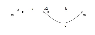
Soln:-
X1- I/p node
X2-Intenmediale node
X3- o/p node
Ab- forward path (p)
Bc- 1 loop (L)
At node XQ:
X2 = x1a + x3c [Add i/p signals at node]
At node x3:
x2b =x3
(x1a+x3c) b = x3
X1ab = x3 (1-bc)
X1 = x3 (1-bc)/ab
Ab/(1-bc) = x3/x1
T= p/1-L

X1:- I/p node x2, x3,x4,x5,Qnlexmedili node
X0:- o/p node abdeg:- forward path
Bc, ef :- Loop [isolated]
x2 = ax1+c x3
x3= bx2
x4 = d x3+f x5
x5 = e x4
x6= g x5
x6 = g(e x4) = ge [dx3+ e f x5]
xb = ge [d (bx2) + f (e x4)]
xb = ge [ db (ax1+cx3) + fe (dx3+ fx5)]
xb = ge [db (ax1+cb (ax1+x3) +fe[cdbx2]+
f( e [db (ax1+ cx3)
x2 = ax1 + cb (x2) x4 = d bx2 + f exq
x2 = ax1 + cbx2 = db (d4) + fe/1-cb
x2 = ax1/(1-cb) xy = db x2 + f x6/g
xy = db [ax1]/1-cb + f xb/g
x5 = c db( ax1)/1-cb + efxb/g
xb = gx5
= gedb (ax1)/1-cb + g efxb/g
Xb = gx5
Gedb (ax1)/1-cb + g efxb/g
(1- gef/g) xb = gedb ax1/1-ab
Xb/x1 = gedb a/ (1- ef – bc + beef
Xb/x1 = p/ 1- (L1+L2) + L1 L2 for isolated loops
The transfer function of a linear time invariant system is the ration of Laplace transform of the output to input.
(a) For open Loop system

G(s) = c(s)/R(s) -------(1)
 (b) For closed Loop system
+
-
G(s) – forward amplification
H(s) _ Reverse amplification
Above system is with negative feedback.
Positive feedback are used only in oscillators and other use is not known as discussing only negative feedback.
[ R(s) – c(s) H (S) ] G(s) = c(s)
R (s) G(s) = [1+G(s) H(s)] c(s)
C(s)/R(S) = G(S)/1+G(s) H(s)
S0, the transfer function of closed Loop system is
C(s)/ R(S) = G(s)/ 1+G(S) H(S) --------(2)
If numerator of above equation (2) is equalized to zero we get zeros of closed Loop Transfer function [G(S) = 0]
If dominator of equation (2) is equaled to zero we get polls of the closed loop transfer function [ 1+G(s) H(S) = 0]
1+ G(S) H(s) = 0 [ characteristic Equation]
Stability of the system is determined by the location of its poles.
Rules of Block diagram Algebra:-
 (1) Block in cascade


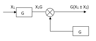 (2) Moving summing point after a block


 +
+
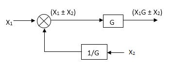 (3) Moving summing point ahead of block
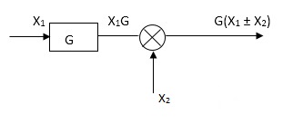


 (4) Moving take off point after a block
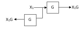 (5) Moving take off point ahead a block


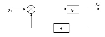
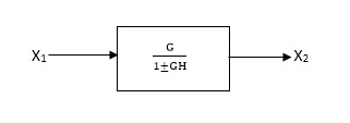 (6) Eliminating a feedback Loop


Q. Reduce given B.D to canonical (simple form) and hence obtain the equivalentTf = c(s)/ R(S) ?


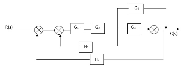


 Sol:-
Sol:-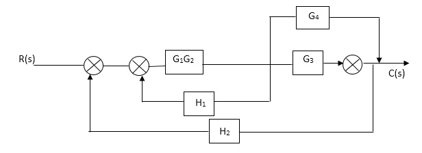


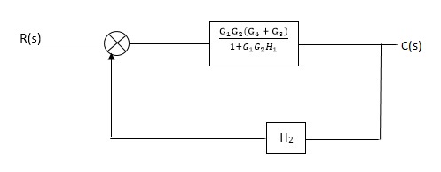
C(S)/R(S) = (G1G2) (G3+G4)/1+G1G2H1)/1-G1,G2(G3+G4) H2/1+G1G2H1
= G1G2(G3+G4)/1+G1G2H1-G1G2H2(G3+G4)
=G1G2(G3+G4)/1+(H1-H2)(G1G2) (G3+G4)
C(s)/R(S) = G1G2(G3+G4)/1+(H1-H2(G3+G4)) G1 G2
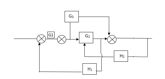 Reduce the Block diagram


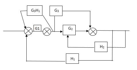
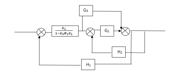


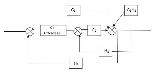


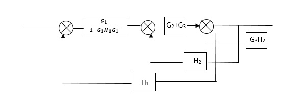


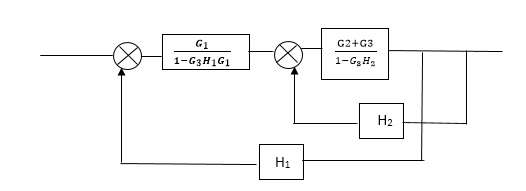


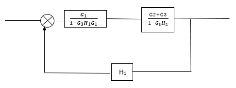


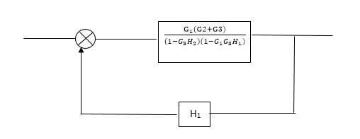
C(s)/R(s)= G1(G3+G2)/(1-G1G3X1) (1-G2X2) H1
= G(G3+G2)/(1-G3G1H1) (1-G2H2) + G1H1(G3+G2)
= G1(G3+G2)/1-63G1H1-G2H2+G1H1(G3+G2H1
=G1(G3+G2)/1-G3H2+G1G2H1(1+G3H2)
MASON’S GAIN FORMULA:-
T= 
The overall transmittance Coverall gain can be determined by Masks formula.
Explationation:-
Pk forward path transmittance of k+n path from a specified i/p node to n o/p nods
While calculating ipnode to n o/p nods.
While calculating ip no node should be encountered (used) more than ones.
 it is the graphics determined which involves of transmittances and multiple increases b/w non touching loops.
 = 1- [sum of all individual loop transmitting]
+[ sum of loop transmittance product of all possible non- touching loops]
-[sum of loop transmittance of all possible triples of non- touching loops]
 path factor associated with concered path & involves all a in the graphic which are isolated from forward path under consideration.
The path factor  for kthis equal to graph determinant of SFG which effect after erasing the kth path from the graph
Q.Reduce using Masons gain formula
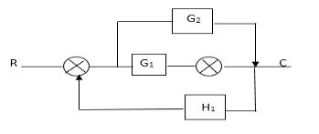
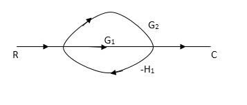
P1= G1 p2 =G2 Delta1 =1
L1= -G1 H1
 = 1-(-G1H1)
= 1+G1H1
T= G1+G2/1+G1H1
Ques:- Determine overall gawreliably x5 and x1 Draw SFG
X2 = ax1+ f x2
X3= bx2 +exy
X4 = cx3+hx5
X5 =dx4 + gx2
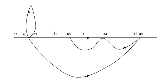
P1 = abcd p2 = ag
L1 = f L2 = ce, L3= dh
 1 = 1
1 = 1
 2= 1-ce
 = 1-[L2+L2+L3] + [L1 L2 +L1 L3]
= 1-[f+ le = dh] + [fce +fdh]
1- T= abcd+ ag (1-ce)/1-[ftce + dh ] + (fce + fdh)
Mechanical System
(a) Translational system
(b) Rotational system
(a) Translational system
The motio that takes place along a straight line is called translational the forces that resist motio are
(I) Intertia: A body with mass ‘N’ accelation ‘a’ will produce inertia fm(t)= malt N’ accelation ‘a’ will produce inertia
fm(t)= M a(t)
In terms of velocity
Fm(t) = M dv(t)/dt
In terms of displacement
Fm(t)= Md2/dt2µt
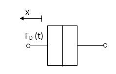 (ii) Damping force : The damping force is proportional to velocity for vis case function
F0(t) = B(t) = B dx(t) /dt
B Damping coefficient N/M sec
(iii) Spring force : A spring stores potential energy The releasing force of a string is proportional to the displacement .
 Fk(t)
Fk(t)  x(t)
x(t)
Fk(t) = k x (t)
Fk(t) = k 
K = string constant N/m.
(b)Rational System:- The motion of a body about a fixed axis is called as Rotational motio The types of lorques which can resist the motion are
i) Inertial Torque:- The inertial torque is the product of moment of inertia I and angular acceleration .
TI(t) = J (t)
(t)
TI(t) = Jd/dt w(t)
TI(t) = Jd2ø(t)/dt2(N-m)
W (t) – Angular velocity
Ø(t) = Angular displacement
(ii) Damping Torque :- it is product of damping efficient B and angular velocity w
T0 (t) = B w(t)
T0(t) = B d/dt ø(t)
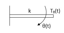 (iii) Spring Torque :- It is the product of torsional stiffness and angular displacement
Tø(t) = k ø(t)
K = N.m/rad
D’Alembert’s Principle
For any body, the algebraic sum of externally applied forces and the forces resisting motion in any given direction is zero.
Ex.
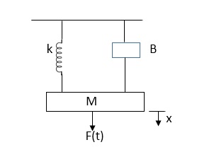
In above figure applying D’Alemberts principle to write the equation of motion
As force f(t) aclsdownwards all other forces (of k,B,x)aclsOpposite to it to considering f(t) as the and all other forces negative.
F(t)+fm (t) + fD(t) +fx(t) =0
f(t)- M d2x(t)/dt2+B dx(t)/dt +x(t)
Q.1 Draw the free body diagram and write the differential equation for system below.
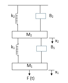
Soln:- The free body diagram for M1 will be
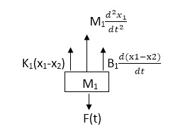
F(t) = M1 d2/dt2x1+ B1 d/dt (x1-x2)+ k1(x1-x2)
Similarly for M2we have
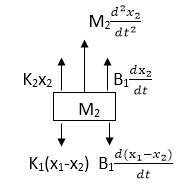
K1(x1-x2) + B1d/dt(x1-x2) = k2x2+M2d2/dt2+B2dx2/dt
Analogy Between Electrical and Mechanical System:-
Force -voltage | Force -current | MechanicalTranslatory | Mechanical Rotational |
1.Voltage (v) | Current | Force (f) | Torque (T) |
2.Charge(q) | Flux (ø) | Displacement(x) | Angular Displacement(ø) |
3.current. | Voltage | Velocity v(t) | Angular velocity(w) |
4.Inductance(l) | Capacitance(c) | Mass (m) | Moment of inertia (J) |
5. Resistance(R) | Conductance G= (1/R) | Damping coefficient (B) | Damping Coefficient (B) |
6.Reciprocal of capacitance(1/c) | Inverse of Inductance (1/L) | Stiffness (K) | Stiffness(K) |
Electrical System
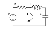
Applying Kirchoff’s voltage Law
V= Ri +Ldi/dt +1/c
V= Rdq/dt + L d2q/dt2+q/c
Now By kirchoff’s current low
I= V/R+ 1/L  + cdv/dt
But V= dø/dt
I= 1/R dø/dt + 1/L ø+cd2ø/dt2
But v= dø/dt
I= 1/R dø/dt+ 1/L. ø+c d2ø/dt2
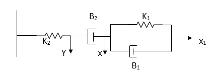 Q.2for the given mechanical system below draw the analogus system (force. Voltage )& find V0(s)/V1(s)
Soln. form the table above we can find the analogus values of system components.
(1) Consider two displacement as two nodes .
(2) If masses are present connect them toreferencelines
(3) Connect other elements of system to the nodes
(4) Applying modalanalysis to find the system equation.
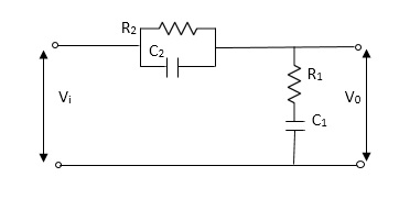
Let Z1 = R2 11 1/c2
=R2*1/c2s/R2+1/c2s
Z1= R2/1+R2c2s
Let Z2 = R1+1/c1s
Z2= 1+R1c1s/c1s
V0(s)/vi(s) = z2/z1+z2
= 1+R1c1s/c1s/R2/1+R2c2s+1+R1c1s/c1s
V0(s)/v0(s) =(c1+R1c1s) (1+R2c2s)/R2c1s+1+sR1c1s2R1R2c1c2
AC/DC Servo Motors
These motors are used in feedback control system. These are also known as control motors. These motors should have low rotor inertia and high speed of response. The servomotors used in the feedback control systems should have linear control signal and rotor speed.
Types of Servomotors:-
(a). A.C. Servomotors
(b). D.C. Servomotors
(a). A.C.Servomotors:-
A.C servomotor is a two-phase ac induction motor. There are two windings in this motor, one is fixed or reference winding is supplied with a fixed voltage and frequency from a constant voltage source. Second winding is control winding with variable supply voltage of same frequency as reference winding but having a phase displacement of 900 electrical. A flux is induced due to the phase change which cuts the conducting bars of rotor and causes a time varying current, this current produces a time varying flux and reacts with the stator flux causing the rotor to rotate.
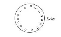
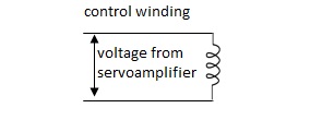
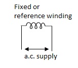
The rotor of A.C. Servomotos are of two types,
(a). Squirrel Cage Rotor
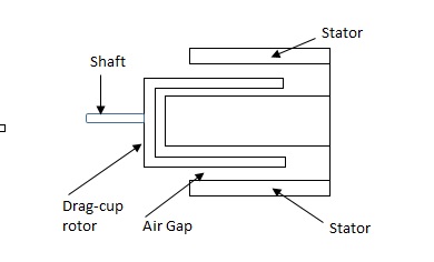
(b). Drag cup type rotor
(a). Squirrel cage rotor :- They have high resistance as the rotor is having large length and small diameter. The air gap here is kept small.

(b). Drag cup type motor :- For the drag cup rotor there are two air gaps. For the rotor a cup of non-magnetic conducting material is used. A stationary iron core is placed between the conducting cup to complete the magnetic circuit. The resistance of drag cup type is high and therefore, has high starting torque. Generally aluminium is used for cup.
Torque-speed characteristic:-
The torque speed characteristics of the two phase servomotor depends on ratio of reactance to resistance(X/R).
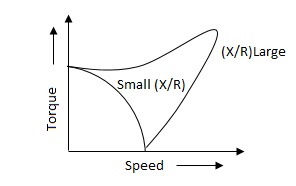
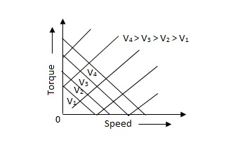
(i). For high ‘R’ and low X, the characteristic is linear and
(ii). For high X and low R, it becomes non-linear.
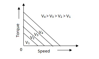
The torque-speed characteristic for various voltage is almost linear.
(b). D.C. Servomotor:-
D.C. Servomotor are separately excited or permanent magnet dc servomotors. The armature of D.C. Servomotors is having large resistance and hence torque-speed characteristic is linear.
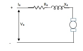
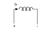
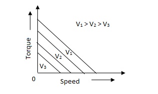
The above graph fig 5(b), clearly shows that the torque-speed characteristics is a function of control winding voltage as shown below.
T = mw + KVc -- (1)
Where T = Torque developed by motor
w = angular velocity
Vc = control winding voltage
Taking laplace of above equation (1),
T(S) = mS Q(S) + KVc - - (2)
T(S) = JS2Q(S) + FSQ(S) - - (3)
Above equation(3) is the dynamic eqution with,
J – moment of inertia
F – coefficient of friction of motor
From equation (2) and (3) the block diagram will be,

Q(S)/Vc = K/Js + F + m - - (4)
Comparison between A.C. Servomotor & D.C. Servomotor
| A.C. Servomotor | D.C. Servomotor |
|
|
|
1. | They are less efficient | They are more efficient |
2. | They have low power output | They have high power output |
3. | No noise so has smooth operation | These motors have noisy operation |
4. | They do not have any radio frequency noise | These motors have brushes so produce radio frequency noise |
5. | They are maintenance free because of no brushes and slip rings | For these motorsmaintenance is required. |
|
|
|
Stepper Motors
It is a device whose output is completely controlled by the input pulses. There are two types of stepper motors:
a) Variable Reluctance
b) Permanent Magnet
A variable reluctance stepper motor consists of stator having a common frame and rotate n a common shaft. Rotor and stator have toothed structure and teeth are of same size so that it can be aligned on same axis. The stator re pulse excited while the rotor is unexcited. When stator is excited stator and rotor teeth are aligned to minimum reluctance position. The stator torque of the rotor depends on the displacement  .
.
There are two positions of zero torque:
i) For  =0 when rotor and stator are aligned is called stable position because slight disturbance from this position in either direction brings the rotor back to its original position.
Ii) For  = 180/T when tooth and stator are aligned is called unstable position. This is because of slight disturbance from this position in either direction makes the rotor move away from it.
For multiple stack stepper motor, Step angle  = 360/nxT
n: number of stacks
T: number of rotor teeth
These motors are used in computer peripherals.
Tacho Generators
These are electromechanical devices which convert mechanical input at their shaft to corresponding electrical output. It is basically used to measure speed of motor. It has negative feedback. These devices are most commonly used to find speed of any rotating machine.
| D.C. Tachometer | A.C. Tachometer |
1. | They convert rotational speed into a proportional dc voltage. | They convert the rotational speed into a proportional ac voltage. |
2. | It uses a permanent magnet for producing magnetic field. It contains iron core rotor. | It works on principle of induction generator. |
3. | The permanent magnet controls the magnetic field therefore the inducevoltage at terminal of armature is proportional to shaft speed. | The reference winding is supplied by reference voltage and the output voltage is induced across the output winding. |
4. | The polarity depends on direction of rotation. | The amplitude and phase depends on the direction of rotation. |
Synchros
Its construction is similar to a three-phase alternator. The stator is made of laminated silicon steel and rotor is dumbbell shaped magnet with a single winding.
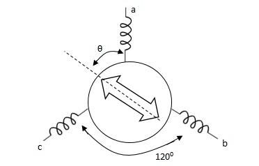
Let the applied a.c. Voltage to the rotor is,
er = ErSinwot
Let the rotor be at angle of ϴ, then voltage in each stator coil with respect to neutral,
Ean = KErSinwot cos(ϴ)
Ebn = KErSinwotcos(ϴ + 1200)
Ecn = KErSinwotcos(ϴ + 2400)
Magnitude of stator terminal voltage,
Ecb = Ecn – Ebn
= KErSinwot[cos(ϴ + 2400) – cos(ϴ + 1200)]
= KErSinwot(√3 Sinϴ)
Ecb = √3KErSinwot Sinϴ
Similarly,
Eac = √3KErSinwot Sin(ϴ + 1200)
Eba = √3KErSinwot Sin(ϴ + 2400)
When ϴ = 0, Ecb, Ean = 0
Hence, input to the synchro transmitter is the angular position of motor shaft and output are three phase voltage which are function of shaft position.
(2). Synchro Transformer :-
Its basic working principle is similar to the synchro transformer. Here the rotor is cylindrical type. It is an electromechanical device. The combination of synchro transmitter and synchro transformer is used as an error detector.
The basic diagram is shown below,
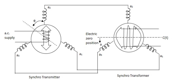
Let transmitter rotate at an angle ϴ and control transformer rotor rotate in same direction through α. Then,
φ = ( 90 - ϴ + α )
Voltage across rotor terminal is given as,
e(t) = K1Vrcos ϴSinwot
e(t) = K1VrSin(ϴ - α) Sin wot
From above equation we can conclude that when two rotor shafts are not aligned, the rotor voltage of transformer is a sine function of difference between two angles.
For small angular displacement between two rotor position,
e(t) = K1Vr(ϴ - α)Sinwot
Magnetic Amplifiers, Servo Amplifiers
Magnetic Amplifiers: They are basically electromagnetic device used for amplification of electrical signals. The basic working of this amplifier depends on the saturation of core principle. It consists of two cores connected in opposite phases, with control and AC winding. By applying small amount of DC currents on control winding large amount of current on AC winding can be controlled. They are of two types
a) Half wave magnetic amplifier: When DC supply is given to the control winding the magnetic flux is generated in the iron core. As flux increases the output impedance decreases and the current through AC winding in output increases. Here only half cycle of AC is utilised.
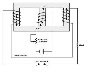
If the current through the control winding is zero, then the impedance of the output winding will be very high making no current to flow through the load or output winding.A diode is connected to the output winding which acts as a rectifier, used for reversing the polarity of the AC supply constantly from cancelling out control winding flux.
b) Full wave magnetic amplifier:It utilizes both the half cycles of the AC supply. Due to wound of the two halves of the output winding the direction of magnetic flux created by these two halves in centre leg is same as direction of control winding flux
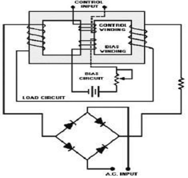
No control voltage is supplied there will be some flux present in magnetic core, hence impedance of the output winding will never attain its maximum value and current through load never attain its minimum value. The operation of the amplifier can be
Controlled by using the bias winding.
Servo Amplifiers: It is an electronic amplifier used to power servomechanism. It monitors the feedback signal and adjusts the deviation if present. When input is applied from control system the servo amplifier amplifies the signal and transmits electric current to a servo motor producing motion proportional to the command signsal.