In TDM the complete channel bandwidth is allotted to one user for fixed time slot. For instance, if there are ten users then every user can be given the time slot of one second. Thus, complete channel can be used by each user for one second time in every ten seconds.
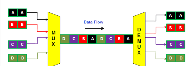
Fig 1 Time Division Multiplexing
This technique is suitable for digital signals because the digital signals are transmitted intermittently and the time spacing between two successive digital codewords can be utilised by other signals. The TDM is classified in two types
Synchronous TDM
In synchronous time division multiplexing, each transmitter is allotted with a fixed time slot, regardless of the fact that the transmitter has any data to transmit or not. The device has to transmit data within this time slot. If the transmitter does not have any data to send then its time slot remains empty.
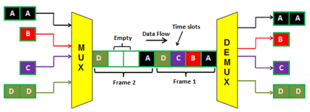
Fig 2 Synchronous TDM
The above figure shows four dedicated time slots A, B, C and D. The transmitter A data is sent at time slot A, transmitter B data is sent at time slot B, transmitter C data is sent at time slot C and transmitter D data is sent at time slot D.
In the time frame 2, the transmitter B and C does not have any data to send so the time slot B and C remains empty.
The main drawback of synchronous time division multiplexing is that the channel capacity is not fully utilized. Hence, the bandwidth goes wasted.
Asynchronous TDM
In this case the time slots are not fixed. The number of transmitters are not equal to the number of time slots. In asynchronous TDM the number of slots are always less than the transmitters.
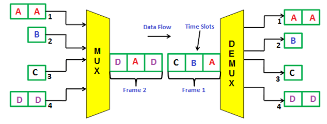
Fig 3 Asynchronous TDM
As seen from above figure the system has four transmitters and 3 time slots. Frame 1 is completely filled with data from devices A, B, C and D. Frame 1 has only 3 time slots. The data from D is filled in frame 2 in timeslot 1. The data from A and D are filled in timeslot 2 and 3 in time frame 2.
In asynchronous time division multiplexing, the multiplexer scans all the transmitters and accepts input only from the devices that have actual data to send and fills all the frames, and then sends it to the receiver. If there is not enough data to fill all the slots in a frame, then the partially filled frames are transmitted. In most of the cases, all the time slots in frames are completely filled.
Key takeaway
This technique is suitable for digital signals because the digital signals are transmitted intermittently and the time spacing between two successive digital codewords can be utilised by other signals
This technique allows to allot a fixed frequency band to every user in the complete channel bandwidth. Such frequency slot is allotted to each frequency user. The figure shows FDM below. The transmitter end contains multiple receivers and transmitters. The transmitter end sends a signal of different frequency. The transmtter1 sends signal of 30kHz, transmitter 2 sends signal of 40kHz and so on as shown below. These signals of different frequencies are multiplexed and transmitted.
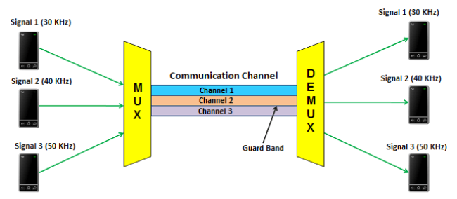
Fig 4 Frequency Division Multiplexing
At the receiver end, the multiplexed signals are separated by using a device called demultiplexer. It then sends the separated signals to the respective receivers. In the above figure, the receiver 1 receives signal of 30 kHz, receiver 2 receives signal of 40 kHz, and receiver 3 receives signal of 50 kHz.
Key takeaway
This technique allows to allot a fixed frequency band to every user in the complete channel bandwidth. Such frequency slot is allotted to each frequency user.
Code division multiplexing (CDM) is a networking technique in which multiple data signals are combined for simultaneous transmission over a common frequency band.
When CDM is used to allow multiple users to share a single communications channel, the technology is called code division multiple access (CDMA).
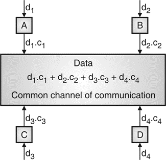
Fig. 5 Communication of station with code
Key takeaway
The basic techniques used for transmissions are listed and explained briefly below.
6.4.1 FDMA
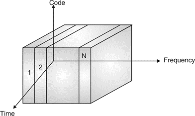
Fig.6 FDMA
Uplink | 890.2 MHz, 915 MHz |
Downlink | 935.2 MHz to 960 MHz |
Uplink (UL) and downlink (DL) can be described with the help of one relation among them as follows:
fd = fu + 45 MHz
If UL frequency is :
fu = 890 MHz + n∙ 0. 2 MHz
Then
fd = 935 MHz + n ∙ 0. 2 MHz
6.4.2 TDMA
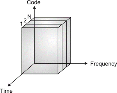
Fig. 6 TDMA
6.4.3 CDMA

Fig.7: Communication of station with code
6.4.4 Mobile Radio
6.4.4.1 Cellular Infrastructure
The cellular system is replaced by large number of base stations (BS) which are hexagonal cells. They cover certain range of areas.
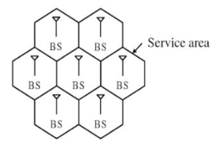
Fig 8 Cellular Structure
For having the communication in cellular structure, we need Mobile station (MS). In these types of structures, the MS communicates with the BS of cell. This is the location of MS in a BS cell. This BS acts as a gateway. For establishing connections, the MS needs to be in the range of the system.
6.4.4.2 Cell Splitting
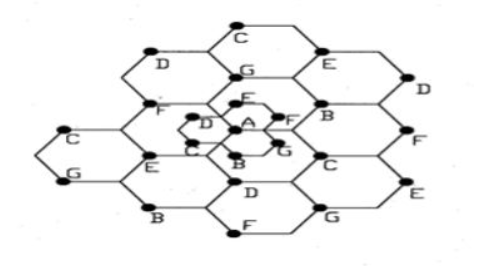
Fig 9 Cell Splitting
6.4.4.3 Frequency reuse
Space Division Multiplexing
Frequency Division Multiplexing
Time Division Multiplexing
Key takeaway
6.4.4.4 Fading and Multipath: Small scale multipath propagation
Multipath causes three major things in wireless communication
6.4.4.5 Synchronous optical network (SONET)
It defines the rate and format for the optical transmission of digital data. The data rates of 51.84Mb/s to 9.953Gb/s are specified by SONET. This system has four layers.
Key takeaway
Approach | SDMA | TDMA | FDMA | CDMA |
Idea | Segment space into cells/sectors | Segment sending time into disjoint time-slots, demand driven or fixed patters | Segment the frequency band into disjoint sub-bands | Spread the spectrum using orthogonal codes
|
Terminals | Only one terminal can be active in one cell/one sector | All terminals are active for short periods of time on the same frequency | Every terminal has its own frequency. uninterrupted | All terminals can be active at the same place at the same moment uninterrupted. |
Signal separation | Cell structure, directed antennas | Synchronization in the time domain | Filtering in the frequency domain | Code plus special receivers |
Advantages | Very simple, increases capacity per km2 | Established, fully digital, flexible | Simple, established robust | Flexible, less frequency planning needed, soft handover |
Disadvantages | Inflexible, antennas typically fixed | Guard space needed (multipath propagation), synchronization difficult | Inflexible, frequencies are a scarce resource | Complex receivers, needs more complicated power control for senders |
Comment | Only in combination with TDMA, FDMA or CDMA useful | Standard in fixed networks, together with FDMA/SDMA used in many mobile networks | Typically combined with TDMA (frequency hopping patterns) and SDMA (frequency reuse) | Still faces some problems, higher complexity, lowered expectations : will be integrated with TDMA/FDMA |
References
1. “Communication Systems”, Simon Haykin, Wiley publication, 4th Edition, 2004
2. “Digital Communication Fundamentals and Applications”, Bernard Sklar, Pearson
Education India, 2nd Edition, 2009
3. “Modern Electronic Communication”, Miller Gary M, Prentice-Hall, 6th Edition, 1999
4. “Digital Communications”, John Proakis, Tata Mc Graw Hill, 5th Edition, 2007
5. “Electronic Communication Systems, Fundamentals Through Advanced”, Wayne Tomsi, Pearson Education, 4th Edition, 2001


