Unit-4
DC Bridges
Kelvin double bridge is the modified version of Wheatstone’s bridge which measure resistance values in the range between 1 to 0.00001 ohms with high accuracy. It derives its name because it uses another set of ratio arm and a galvanometer to measure the unknown resistance value.
The construction of Kelvin double bridge consists of 2 arms “P & Q”, “p & q” where the arm “p & q” is connected to one end of the galvanometer, at “d” and “P & Q” is connected to another end of the galvanometer, at ‘b’. This connection minimizes the effect of connecting lead and the unknown resistor R & a standard resistor S is placed between ” m and n”, and “a and c”.
|
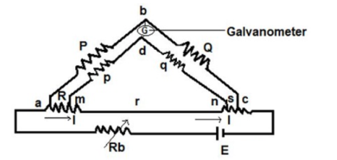
Figure1. Kelvins Double Bridge
Derivation The ratio p/q = P/Q, Under the balanced condition current in galvanometer = 0 Potential difference at a & b = voltage drop between Eamd . Eab = [P / P+Q ] Eac Eac = I [ R + S + [( p+q)r] / [p+q+r]] …………(3) Eamd = I [ R + (p / (p+q)) * {(p+q) r / (p+q+r)}] Eac = I [ p r / ( p+q+r)] ………(4) When galvanometer shows zero then (P / P+Q) * I [ R + (p / (p+q)) * {(p+q) r / (p+q+r)} ] = I [ p r / (p+q+r)] R = (P /R)* S + p r / (p+q+r) [ (P/Q) – (p/q)] We know that P/Q = p/q R = (P/Q) * S …….(5) |
For obtaining perfect results, the arms ratio should be maintained equal and the thermo-electric electromagnetic field induced in the bridge while taking readings can be reduced by interchanging the polarity of the connection. Therefore the unknown resistance value can be obtained from the two arms.
Key Takeaways:
A kelvin bridge or kelvin double bridge is a modified version of the Wheatstone bridge, which can measure resistance values in the range between 1 to 0.00001 ohms with high accuracy.
4 1.1 Wheatstone Bridge
It has four resistive arms, consisting of resistances P, Q R and S together with a source of emf that is battery and null detector galvanometer G or another sensitive current meter. The current through the galvanometer depends on the potential difference between points c and d.
The bridge is said to be balanced when there is no current through the galvanometer or when the potential difference across galvanometer is zero.
The balanced condition occurs when voltage from point b to point an equal to voltage from point d to point b or by referring to the other battery terminal when the voltage from point d to point c equals the voltage from point b to point c.
|
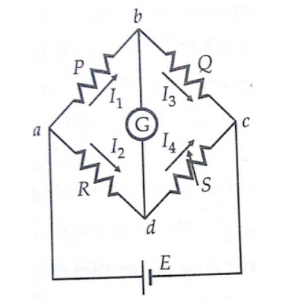
Figure 2. Wheatstone bridge for measurement of medium resistance.
For a balanced condition, we can write, I1 P = I2 R ---------------------(1)
For the galvanometer current to be zero, the following conditions also exist:
I1 = I3 = E/P+Q-----------------------------(2) I2 = I4 = E/R+S ---------------------------------(3) where E = emf of the battery Combining the above three equations we get,
P/P+Q = R/R+S --------------------------------(4) from which Q.R = P.S ----------------------------------------------------------------(5) R = S*(P/Q)
|
Key Takeaways:
The Wheatstone Bridge is used to measure unknown resistance values as means of calibrating measuring instruments, voltmeters, ammeters, and so on by the use of a long resistive slide wire.
Example
|
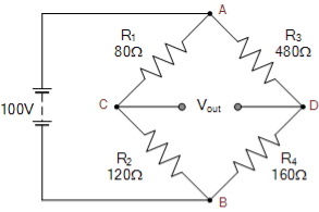
For the first series arm, ACB
Vc = R2/(R1+R2) x Vs
Vc = 120Ω/ 80Ω + 120 Ω x 100 = 60 volts
For the second series arm, ADB
VD = R4/(R3+R4) x Vs
VD = 160Ω/ 480Ω + 160Ω x 100 = 25 volts
The voltage across points C-D is given as:
Vout = VC – VD
Vout = 60 -25 = 35 volts
The value of resistor, R4 required to balance the bridge is given as:
R4 = R2R3/R1 = 120Ω x 480Ω/80Ω = 720 Ω |
A Wheatstone bridge is used for measuring the value of change of resistance of a strain gauge which forms one of the arms of the bridge. All the arms of the bridge including the strain gauge have a resistance of 100 Ω each. The maximum allowable power dissipation from the strain gauge is 250mW. Determine the value of maximum permissible current through the strain gauge and maximum allowable value of bridge supply voltage. Suppose a source of 20V is available find the value of series resistance to be connected between the source and the bridge to limit the input voltage of the bridge to permissible level.
Solution:
The resistance of strain gauge R = 100Ω. Suppose I is the current through each arm under balanced conditions
I 2 R = P where P = power dissipation
Hence maximum permissible current =  P/R =
P/R =  250 x 10 -3 /100 = 0.05A = 50 mA.
The maximum allowable voltage which can be applied to the bridge
= 2 x 50 x 10 -3 x 100 = 10V
Voltage across the series resistor = 20 – 10 = 10V
Current through the series resistor = 2 x 50 x 10 -3 x 100 x 10 -3
Resistance of series resistor Rs = 10/100 x 10 -3 = 100Ω
4.1.2 Carey-Foster Bridge
The Carey foster bridge circuit diagram is shown below. There are two units in the circuit
- Bridge Unit
- Testing Unit
|
Figure3. Carey Foster Bridge Circuit
Carey Foster Bridge Circuit
The testing unit contains the power supply, galvanometer, and variable resistances which has to be measured. The DC supply is applied to eliminate the issues of battery discharge concerning time.
From the figure, the bridge circuit is constructed with P, Q, R, and S resistances. P and Q are the known resistances used for comparison. R and S are unknown resistances to be measured. The slide wire with a length L is placed between the resistances R and S as shown in the figure. To equalize/equivalent the ratios of resistances P/Q and R/S, the values of P and Q can be adjusted. Slide the contact of the slide wire to equivalent the resistance ratio.
Consider I1 to be the distance from the left side where the bridge is balanced. Interchanging the resistances R and S the bridge gets balanced by sliding the contact with distance I2.
P/Q = (R+I1 r)/ [(S+(L+I1) r]
Where r = resistance/unit length of the slide wire.
Now interchange the resistances R and S. Then the balanced equation for the bridge circuit is given as,
P/Q = (S+I2r)/[R+(L-I2)] For the first balance equation, we get, P/Q + 1 = [(R+I1r+ S+(L-I1)r]/[S+(L-I1)r] -------(1) P/Q = (R+S+I1r)/(S+(L-I1)r) We get a second bridge balance equation as P/Q + 1 = [ S + I2 r + R + (L-I1) r] / [R + (L-I2) r] -----------------------------(2) P/Q +1 = (S+ R+ Ir) /(R+(L-I2) r) From the above equations (1) and (2) S + (L-I1) r = R +(L-I1) r S-R = (I1-I2) |
At the bridge balance condition, the difference between the resistances S and R is equal to the difference of distance between the lengths l1 and l2 of the slide wire.
Hence this type of bridge circuit is also called as Carey foster slide wire bridge circuit.
Problem:
In a Carey-Foster’s bridge a resistance of 1.0125Ω is compared with a standard resistance of 1.0000Ω, the slide wire has a resistance of 0.0250 Ω in 100 divisions. The ratio of arms nominally each 10Ω are actually 10.05 and 9.95 Ω respectively. How far are the balance positions from those which would obtain of ratio arms to their nominal value? The slide wire is 100cm long.
Solution:
Balance with ratio arms equal to nominal values
Let I1 be the distance of balance point of slide wire from the unknown resistance end in cm of slide wire. Let r be the resistance per cm length of slide wire. Let r be the resistance per cm length of slide wire r = 0.0250/100 = 0.00025Ω/cm as length of wire is 100cm. In this case P=Q=10Ω , S=1.000 and R=1.0125Ω Under balance conditions P/Q = R+I1r/S+(100-I1)r or 10/10 = 1.0125+ 0.00025 I1 / 1.0000+0.025-0.00025I1 Thus, the balance obtained at 25 and 75 scale divisions. Balance arms equal to true values In this case P =9.05 Ω and Q = 10.05 Ω Under Balance conditions 9.95/10.05 = 1.0125+0.00025I1/ 1.0000+0.025-0.00025I1 or 1-0.005/1+0.005 = 1.0125+0.00025I1/ 1.0250-0.00025I1 I1 = 5cm |
Key Takeaways:
The Carey Foster bridge is a bridge circuit used to measure medium resistances, or to measure small differences between two large resistances.
4.2.1 Maxwell Bridge
Li =unknown inductance of resistance Ri,
L2=variable inductance of fixed resistance r2,
Ra=variable resistance connected in series with inductor L2, and
R3,R4=known non-inductive resistances .
|
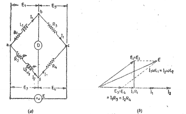
Figure 4. Maxwells Inductance Bridge
At balance
L1 = R3/R4 L2
R1 = R3/R4 (R2+r2)
4.2.2 Hays Bridge
The Hay's bridge is a modification of Maxwell's bridge. The block diagram and the phasor diagram for this bridge are shown in Figure. The bridge uses a resistance in series with the standard capacitor.
|
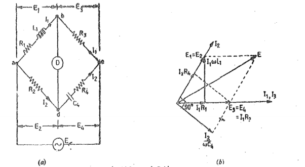
Figure 5. Hay’s Bridge
Let L1 =unknown inductance having a resistance Ri, R2, Ra. R4=known non-inductive resistances, and C4=standard capacitor. At balance, (R1+jwL1)(R4-jwC4) = R1R3 or R1R2+L1/C4+jwL1R4-jR1/wC4=R2R3 Separating the real and imaginary terms we obtain R1R4+L1/C4=R2R3 and L1 =R1/w 2 R4C4 Solving the two equations we have L1 = R2R3C4/1+w 2 C42 R4 2 ---------------(1) R1 = w 2 R2 R3 R4 C4 2/ 1+ w 2 c4 2 R4 2 ----------------------------------------------(2) The Q factor of the coil is Q=wL1/R1 = 1/wC4R4-------------------------------------(3) |
4.2.3 Owens Bridge
This bridge may be used for measurement of an inductance in terms of capacitance . Figure shows the connection and phasor diagrams for this bridge under balance conditions
|
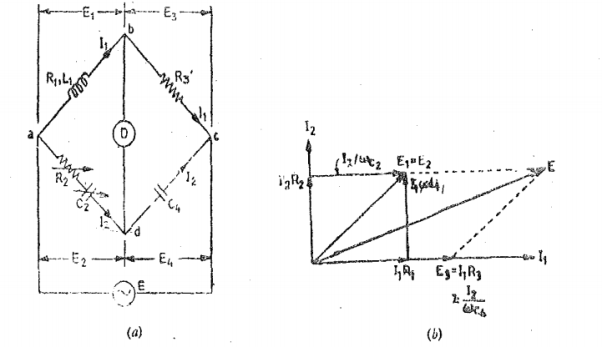
Figure 6. Owen’s Bridge
Let L1=unknown self-inductance of Resistance R1 R2 = variable non-inductive resistance C2 = variable standard capacitor R3 = fixed non-inductive resisstance C4 = fixed standard capacitor. At balance (R1 + jwL1)(1/jwC4)= (R2 + 1/jwC2)R3 Seperating real and imaginary terms we obtain L1 = R2R3C4 R1 = R3 C4/C2 |
4.2.4 Anderson Bridge
|
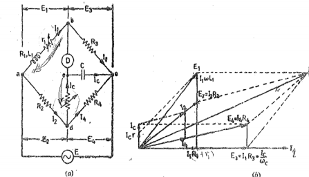
Figure 7. Anderson Bridge
Let L1= self-inductance to be measured. R1 = resistance of self -inductor r 1 = resistance connected in series with self-conductor C = fixed standard capacitor R, R2, R3, R4 are known non inductive resistances. At balance I1=I3 and I2=Ic+I4 I2R3 =Ic x 1/jwC Ic = I1jwCR3 Writing the other balance equation I1(r1+R1+jwL1) = I2R2+Icr and Ic(r+1/jw) = (I2-Ic) R4. Substituting the values of Ic in the above equation we get I1(r1+C1+jwL1) =I2R2+I1jwC or I1(r1+R1-jwCR2r) =I2R2 ------(i) And jwCR2 I1(r+1/jwC) = (I2-I1jwcR2) R4 or I1(wCR2r+jwCR3R4+R3) = I2R4—(ii) From (i) and (ii) we get I1(r1+R1+jwL1-jwCR2r) = I1(R2R3/R4+jwCR2R3r/R4 +jwCR3R2) Equating real and imaginary terms R1=R2R3/R1 -r1 And L1=CR3/R4[r(R4+R3) +R2R4 |
4.2.5 Wein Bridge
The Wien’s bridge is frequency sensitive. The input supply voltage is not purely sinusoidal, and they have some harmonics. The harmonics of the supply voltage disturbs the balance condition of the bridge. To overcome this problem the filter is used in the bridge. The filter connects in series with the null detector.
A Wien-Bridge network as shown in Figure comprises of four arms connected in a bridge fashion. Here two arms are purely resistive while the other two arms are a combination of resistors and capacitors. One arm has resistor and capacitor connected in series (R1 and C1) while the other has them in parallel (R2 and C2).
|
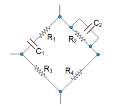
Figure8. Wein Bridge Network
In this circuit, at high frequencies, the reactance of the capacitors C1 and C2 will be much less due to which the voltage V0 will become zero as R2 will be shorted. Next, at low frequencies, the reactance of the capacitors C1 and C2 will become too high.
The resonant frequency for a Wein Bridge Oscillator is calculated using the following formula:
fr = 1/ 2π  R1C1R2C2 if R1=R2=R and C1=C2 = C then
fr = 1/2 π RC
4.2.6 Schering Bridge
|
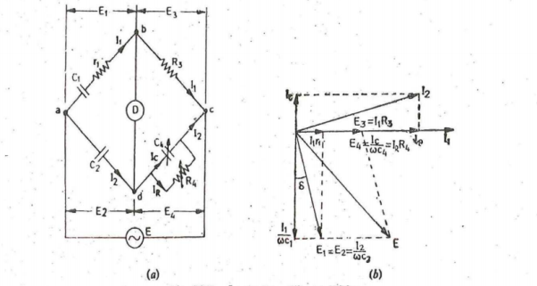
Figure 9. Schering Bridge (low voltage)
Let C1 = capacitor whose capacitance is to be determined r1 = series resistance representing the loss in the capacitor C1. C2 = standard capacitor. R3 = non-inductive resistance C4 = variable capacitor R4 = variable non-inductive resistance in parallel with variable capacitor C4. At Balance (r1+1/jwC1) (R4/ 1+jwC4R4) = 1/jwC2. R3 ( r1 + 1/jwC1) R4 = R3 / jwC2 (1+jwC4R4) r1R4 – jR4/wC1 = -jR3/wC2 + R3R4C4/ C2 Equating real and imaginary terms we obtain r1 = C4/C5 xR3 And C1 = R4/R3 x C2 Two independent balance equations are obtained if C4 and R4 are chosen as the variable elements Dissipation factor D1 = tan ɸ = w C1 r1 = w . R4/R3 . C2 . C4/C2 . R3 = wC4R4 |
4.2.7 Heaviside-Campbell Bridge
This bridge as shown in figure measures mutual inductance in terms of known self-inductance. The same bridge was used by Campbell to measure self-inductance in terms of known mutual inductance.
|
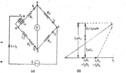
Figure 10. Campbell Bridge
Let M = unknown mutual inductance L1 = self-inductance of secondary of mutual inductance L2= known self inductance R1,R2,R3,R4 = non-inductive resistors At balance voltage drop between b and c must equal the voltage drop between d and c . Also the voltage drop across a.b.c must equal the voltage drop across a-d-c. Thus we have the following equations at balance I1R3 = I2R4 (I1+I2)(jwM) +I1(R1+R3+jwL1) = I2(R2+R4+jwL2) And I2(R4/R3+1) jwM +I2 R4/R3 (R1+R3+jwL1) = I2(R2+R4+jwL2) or jwM(R4/R3+1) +R4/R3.R1+R4+jwL1.R4/R3= R2+R4=jwL2 Thus R1R4=R2R3 M= L2-L1R4/R3/R4/R3+1 = R3L2-R4L1/R4+R3 It is clear from the above equation that L1 the self-inductance of the secondary of the mutual iductor must be known in order that M be measured by this method. In this case R3 = R4 we get M = L2 -L1/2 and R1 = R2. |
Key Takeaways:
AC bridges are the circuits that are used for the measurement of electrical quantities such as inductance, capacitance, resistance
References:
- Elements of Electronic Instrumentation and Measurement – by Carr
- Basic Electrical, Electronics and Measurement Engineering Paperback – 1 January 2019 by U.A Bakshi and A.P Godse.
- Electrical and Electronic Measurement and Instrument Paperback R.K Rajput
- Electrical & Electronic Measurements B. P. Patil, Pooja Mogre (Bisen)
- Electronic Measurements and Instrumentation by A.K. Sawhney


