Unit-1
Database system architecture
● A major objective of database systems is to provide users with an abstract view of the data.
● The system hides details of how the data is stored and maintained.
● Database systems has to provide an efficient mechanism for data retrieval.
● Efficiency leads to the design of complex data structure for representation of data in databases.
● This complexity must be hidden from users.
● This can be done by providing several levels of abstractions.
● In the Three Schema Architecture, three levels of abstraction have been created.
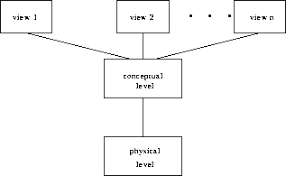
Fig 1: Data abstraction
These are: -
➢ Logical level : This is the middle stage of the architecture of 3-level data abstraction. This explains what information is contained in the database.
➢ View level : Highest data abstraction standard. This level defines the relationship between users and the database system.
➢ Physical level : This is the lowest data abstraction level. This explains how the data in the database is actually stored. At this step, you can get the complex information of the data structure.
Key takeaway:
- The system hides details of how the data is stored and maintained.
- Complexity must be hidden from users.
In addition to users' data, a database system usually includes a lot of data. For instance, to easily locate and retrieve data, it stores information about data, known as metadata. Modifying or modifying a collection of metadata once it is placed in the database is very difficult. But when a DBMS expands, in order to fulfil the users' requirements, it needs to evolve over time. It will become a boring and highly complicated job if the entire data is based.
Metadata itself follows a layered model, such that it does not impact the data at another level when we modify data on one layer. This data is independent, but is mapped to one another.
Types of data independences
❏ Physical data independence
Physical Data Independence is defined as the ability to make adjustments without affecting the higher-level schemas in the structure of the lowest level of the Database Management System (DBMS). Therefore, the Physical level adjustment does not result in any adjustments to the Conceptual or View levels.
❏ Logical data independence
Logical Data Independence is defined as the ability to make improvements to the Database Management System (DBMS) middle level structure without affecting the schema or application programmes at the highest level. Changes to the conceptual level should also not result in any changes to the view levels or programmes of the application.
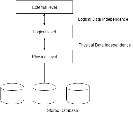
Fig 2: data independence
Key takeaway:
- The freedom of logical data refers to the ability to alter the conceptual schema without the external schema needing to be modified.
- Independence of physical data can be defined as the ability to alter the internal schema without the conceptual schema having to be modified.
In reality, the DDL or Data Description Language consists of SQL commands that can be used to define the schema for the database. It basically deals with database schema definitions and is used to construct and change the configuration of database objects in the database.
Some of the commands that fall under DDL are as follows:
● CREATE
● ALTER
● DROP
● TRUNCATE
CREATE
It is used in the database for the development of a new table
Syntax
CREATE TABLE TABLE_NAME (COLUMN_NAME DATATYPES[,....]);
Example
CREATE TABLE STUDENT(Name VARCHAR2(20), Address VARCHAR2(100), DOB DATE);
ALTER
It is used to modify the database structure. This move may be either to change the characteristics of an existing attribute or to add a new attribute, likely.
Syntax
In order to add a new column to the table:
ALTER TABLE table_name ADD column_name COLUMN-definition;
To change the current table column:
ALTER TABLE MODIFY(COLUMN DEFINITION....);
Example
ALTER TABLE STU_DETAILS ADD(ADDRESS VARCHAR2(20));
ALTER TABLE STU_DETAILS MODIFY (NAME VARCHAR2(20));
Drop
It is used to delete both the structure of the table and the record.
Syntax
DROP TABLE ;
Example
DROP TABLE STUDENT;
TRUNCATE
It is used to erase from the table all rows and free up the space containing the table.
Syntax
TRUNCATE TABLE table_name;
Example
TRUNCATE TABLE STUDENT;
To change the database, DML commands are used. It is responsible for all forms of database changes.
The DML command is not auto-committed, which means all the changes in the database will not be permanently saved. There may be rollbacks.
Commands under DML
a. INSERT
The INSERT statement is a query from SQL. It is used for the insertion of data into a table row.
Syntax
INSERT INTO TABLE_NAME
(col1, col2, col3,.... Col N)
VALUES (value1, value2, value3, .... ValueN);
Or
INSERT INTO TABLE_NAME
VALUES (value1, value2, value3, .... ValueN);
b. UPDATE
This command is used to update or alter the value of a table column.
Syntax
UPDATE table_name SET [column_name1= value1,...column_nameN = valueN] [WHERE CONDITION]
c. DELETE
It is used to extract a table from one or more rows.
Syntax
DELETE FROM table_name [WHERE condition];
Types of DML: -
a. Procedural: -
It requires a user to specify what data is needed and how to retrieve it from database. The user instructs the system to perform a sequence of options on the database to compute the desired result.
b. Non-Procedural: -
It requires a user to specify what data is needed without specifying how to get it.
The modelling of the data description, data semantics, and consistency constraints of the data is the Data Model. It offers conceptual resources at each level of data abstraction to explain the architecture of a database.
Data models are used to describe the design of a database at the logical level.
Some of the data models are: -
1. Entity-Relationship Model
2. Relational Model
4. Network Model
5. Object Relational Model
1.5.1 Entity-relationship model
● The logical structure of a database can be expressed by an E-R diagram.
● Relationships are defined in this database model by dividing the object of interest into an entity and its characteristics into attributes.
● Using relationships, various entities are related.
● To make it easier for various stakeholders to understand, E-R models are established to represent relationships in pictorial form.
The Main Components of ER Diagram are: -
a) Rectangles - Entity Sets
b) Ellipses - Attributes
c) Diamond - Relation among entity sets
d) Lines - Connects attributes to entity sets and entity sets to relationships.
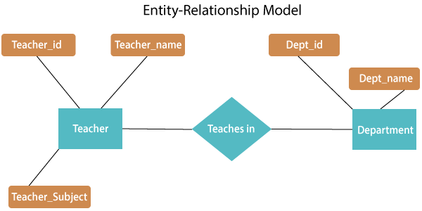
Fig 3: E-R relationship
The above E-R diagram has two entities: Teacher and Department
Teacher entity has three attributes:
Teacher_id
Teacher_name
Teacher_Subject
Department entity has two attributes: -
Dept_id
Dept_name
Relation Teaches in gives relationship between Teacher, Department.
Relationship can be of the type:
1:1 → One to one
1:M → One to many
M:1 → Many to one
M:M → Many to many
Key takeaway:
- The logical representation of data as objects and relations among them is an ER model.
- These objects are known as entities, and an interaction between these entities is an association.
1.5.2 network model
● Network model uses two different data structures: -
a) A record type is used to represent as entity set.
b) A set type is used to represent a directed relationship between two record types.
● This is the Hierarchical model's extension. Data is arranged more like a graph in this model, and is allowed to have more than one parent node.
● Data is more linked in this database model as more relationships are formed in this database model. Also, as the data is more linked, it is also simpler and quicker to access the information. To map many-to-many data relationships, this database model was used.
● This was the most commonly used database architecture prior to the advent of the Relational Model.
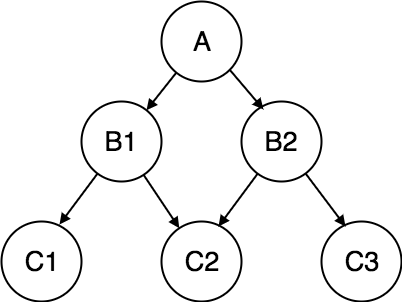
Fig 4: network model
Key takeaway:
- Network model is the Hierarchical model's extension
- Data is arranged more like a graph in this model, and is allowed to have more than one parent node.
1.5.3 relational and object-oriented data models
Relational model
● Relational model uses a collection of tables to represent both data and the relationships among those data.
● This model is useful for constructing a database that can then be converted into relational model tables.
● Data is arranged in two-dimensional tables in this model and the relationship is preserved by storing a common field.
● In the relational model, the basic structure of data is tables. In the rows of that table, all information relating to a specific category is stored.
Therefore, in the relational model, tables are also known as relations.
Sample relational database
- Teacher Table
Teacher_id | Teacher_name | Teacher_Subject |
1001 | Pritisha | C++ |
1002 | Akon | DBMS |
1003 | Rahul | SE |
1004 | Raj | Data structure |
B. Department Table
Dept_id | Dept_name |
A101 | CSE |
B102 | Electronics |
C103 | Civil |
D104 | Mechanical |
C. Teaches in table
Teacher_id | Dept_id |
1001 | A101 |
1002 | B102 |
1003 | C103 |
1004 | D104 |
Object oriented data model
The object-oriented database derivation is the integrity of object-oriented
Programming language systems and consistent systems. The power of the object-oriented databases comes from the cyclical treatment of both consistent data, as found in databases, and transient data, as found in executing programs.
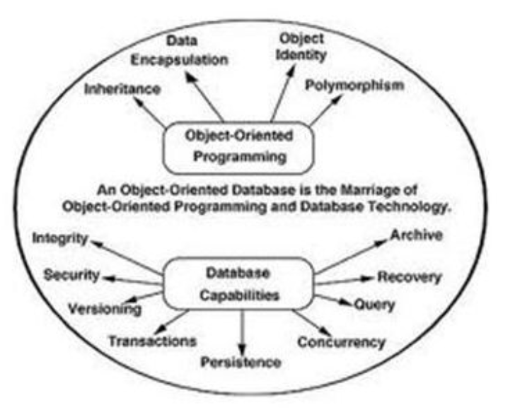
Fig 5: object-oriented model
Object-oriented databases use small, recyclable separated of software called objects. The objects themselves are stored in the object-oriented database. Each object contains of two elements:
1. Piece of data (e.g., sound, video, text, or graphics).
2. Instructions, or software programs called methods, for what to do with
The data.
There are two types of ORM: -
a. Object-Oriented Data Model (OODM)
b. Object-Relational Data Model (ORDM)
These models are used to handle objects:
1) To provide support for complex objects.
2) To provide user extensibility for data types operators and access methods.
3) There should be mechanism to support:
a) Abstract data type.
b) Data of type ‘procedure’.
c) Rules.
Key takeaway:
- The logical structure of a database can be expressed by an E-R diagram.
- Relational model uses a collection of tables to represent both data and the relationships among those data.
- Object-oriented databases use small, recyclable separated of software called objects.
Constraints on honesty are a set of rules. It is used to maintain information quality.
Integrity constraints ensure that it is important to perform data insertion, updating, and other procedures in such a way that data integrity is not compromised.
Therefore, to protect against unintended damage to the database, integrity constraints are used.
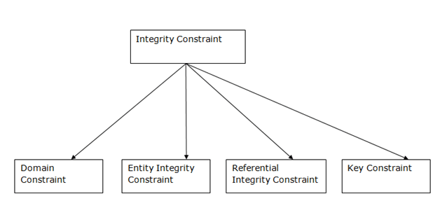
Fig 6: types of integrity constraints
- Domain Constraints
● As a description of a valid set of values for an attribute, domain constraints can be specified.
● The domain data type consists of a string, character, integer, time, date, currency, etc. In the corresponding domain, the value of the attribute must be available.
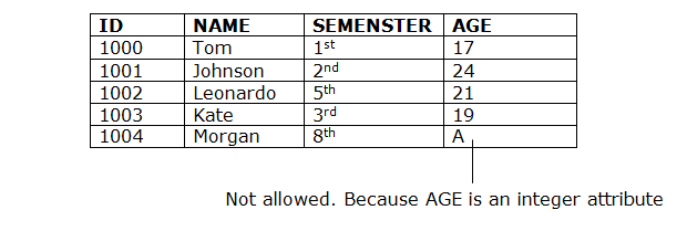
Fig 7: example of domain constraints
B. Entity Integrity Constraints
● The honesty restriction of the organization states that the primary key value should not be zero.
● This is because the primary key value is used to define the relationship between individual rows, and if the primary key has a null value, then those rows cannot be identified.
● A table may contain a null value other than the field for the primary key.
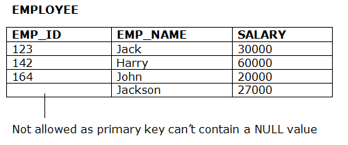
Fig 8: example of entity constraints
C. Referential Constraints
● Between two relations or tables, the referential integrity constraints are defined and used to preserve the consistency between the tuples in two relationships.
● If an attribute of the foreign key of the relationship R1 has the same domain(s) as the primary key of the relationship R2, then the foreign key of R1 is said to refer to or refer to the primary key of the relationship R2.
● Foreign key values in the R1 relationship tuple can either take the primary key values for a certain R2 relationship tuple, or they can take NULL values, but cannot be zero.
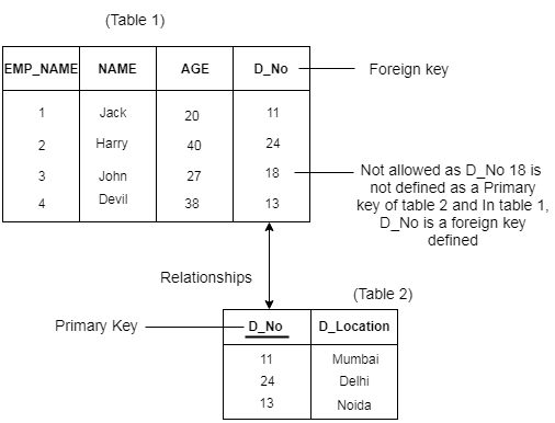
Fig 9: example of integrity constraints
D. key Constraints
● Keys are the collection of entities used to uniquely define an object within its entity set.
● A group of entities may have several keys, but the primary key will be one key. A primary key may contain in the relational table a unique and null value.
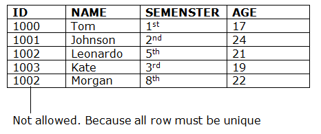
Fig 10: example of key constraints
Key takeaway :
- Constraints on honesty are a set of rules.
- It is used to maintain information quality.
- The domain data type consists of a string, character, integer, time, date, currency.
- Between two relations or tables, the referential integrity constraints are defined.
- Keys are the collection of entities used to uniquely define an object within its entity set.
Some Data manipulation operations are :
❖ SELECT
The Select Statement retrieves data from the database as defined by the constraints.
Select command with some clauses :
SELECT <COLUMN NAME>
FROM <TABLE NAME>
WHERE <CONDITION>
GROUP BY <COLUMN LIST>
HAVING <CRITERIA FOR FUNCTION RESULTS>
ORDER BY <COLUMN LIST>
Syntax
SELECT * FROM <table_name>;
Example
SELECT * FROM student;
OR
SELECT * FROM student
Where age >=15 ;
❖ INSERT
The INSERT statement is a query from SQL. It is used for the insertion of data into a table row.
Syntax
INSERT INTO TABLE_NAME (col1, col2, col3,.... Col N)
VALUES (value1, value2, value3, .... ValueN);
Or
INSERT INTO TABLE_NAME
VALUES (value1, value2, value3, .... ValueN);
Example
INSERT INTO student (sid int, sname varchar(20), city varchar(20))
VALUES (1, XYZ, MUMBAI);
❖ UPDATE
This command is used to update or alter the value of a table column.
Syntax
UPDATE table_name SET [column_name1= value1,...column_nameN = valueN] [WHERE CONDITION]
Example
UPDATE student
SET age=20
WHERE sname='XYZ';
❖ DELETE
It is used to extract a table from one or more rows.
Syntax
DELETE FROM table_name [WHERE condition];
Example
DELETE FROM student
WHERE sid = '1';
MERGE
Use the MERGE statement to pick rows for updating or insertion into another table from one table. In the ON clause, the decision whether to update or insert in the target table is based on a condition. The combination of UPDATE and INSERT is also known as UPSERT.
Syntax
MERGE <TARGET TABLE> [AS TARGET]
USING <SOURCE TABLE> [AS SOURCE]
ON <SEARCH CONDITION>
[WHEN MATCHED
THEN <MERGE MATCHED > ]
[WHEN NOT MATCHED [BY TARGET]
THEN < MERGE NOT MATCHED >]
[WHEN NOT MATCHED BY SOURCE
THEN <MERGE MATCHED >];
Key takeaway:
- It is a language that is used in a database to select, insert, remove and update data.
- It is used in a relational database to retrieve and manipulate data.
References:
- “Database System Concepts”, 6th Edition by Abraham Silberschatz, Henry F. Korth, S. Sudarshan, McGraw-Hill
2. “Foundations of Databases”, Reprint by Serge Abiteboul, Richard Hull, Victor Vianu, Addison-Wesley