Unit - 1
Flexible transmission elements
- Belt drive is used to transmit power from one shaft to another shaft by using pulleys which rotate at same speed or at different speed. Belt drives are used when shafts are at considerable distance apart from each other.
- A belt drive consists of three elements: 1) Driver Pulley (Also known as Driving or Head Pulley) 2) Driven Pulley (Also known as Tail Pulley) 3) Belt
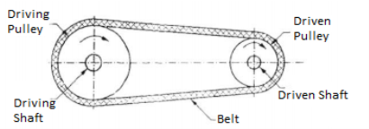
- The belt is passed over the driving and driven pulleys which are mounted at different shafts. The Driving pulley is mounted on the Shaft of prime mover while Driven pulley is mounted on power absorbing machine.
- In belt drive, power is transmitted from the driving pulley to the driven pulley due to friction between the belt and pulley surface.
- It is not a positive drive as because always there can be small amount of slip present.
- Speed Ratio (Velocity Ratio) of belt drive is the ratio of Speed of Driving Pulley to the Speed of Driven Pulley.


Where,
- N1 = Speed of Driver Pulley in (RPM)
- N2 = Speed of Driven Pulley in (RPM)
- D1= Diameter of Driver Pulley
- D2= Diameter of Driven Pulley
- t = Thickness of Belt
- Thus From above equations speed ratio can also be written as,

Linear Speed of Belt

-------- Linear Speed of Belt in mm/sec OR m/sec
Power Transmission Capacity ofBelt Drive

Power transmitted from driving pulley
 Power transmitted from Driven pulley
Where,
- P = power transmitted, ( in Watt)
- T1 = torque on driver pulley, N-m
- T2 = torque on driven pulley, N-m
- As efficiency of belt drives is 98%, soit is assumed as 100%. Hence power from driving and driven pulley is considered as same.
- From equation 2 and 3


From equation 1 & 4,

Types of Belts
• Flat Belt Drive
• V Belt Drive
• Timing/Toothed Belt


- Flat Belt Drive
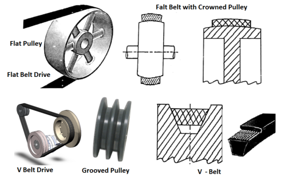
- Flat belts are as show in the figure have rectangular cross section. In flat belts the width of belt is substantially higher than thickness of belt. These belts have joint.

Figure: Flat belt Pulley
- They can be used to transmit a moderate amount of power from one pulley to another over long Centre distances when the two pulleys are at a distance of up to 15 meter fromeach other.
- In flat belt drives, the pulleys are provided with proper crowning to avoid coming off of the belt from the pulley. Such pulleys are known as crowned pulleys.
- Desired Properties of the belt material : 1) High Coefficient of Friction 2) Flexibility 3) Durability 4) High Strength
- Material for Flat belt: Rubber, Leather, Fabric etc.
Advantages of Flat Belt Drive:
1) Can transmit power over long Centre distance upto 15 meter.
2) Relatively cheap and easy to maintain.
3) High efficiency upto 98%.
Limitations of Flat Belt Drive:
1) Slip is more. They are large in size and occupy more space.
2) Cannot be used for short centre distances.
3) They cannot transmit high power.
4) Their operation is noisy.
Applications of flat belt drive:
1) To drive Flour mill, Stone Crushers and industrial application.
Types of Flat Belt:
- Open Belt Drive
- Cross Belt Drive
- Compound Belt Drive
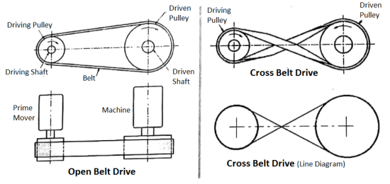
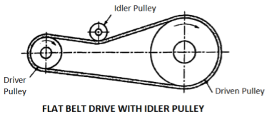
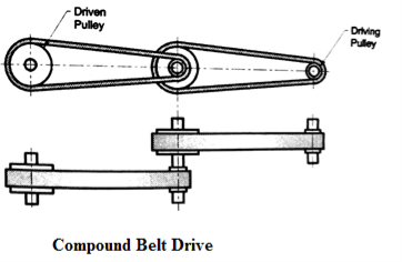
- Observe various Figures of belt drives given below.
Open Belt Drive:
- In Open belt drive, both the pulleys rotate in same direction. It is used to transmit moderate power when both shafts are parallel and centre distance is upto 15 meter.
- Open belt drive with an idler pulley is used to obtain desired belt tension, high speed ratio and higher power transmission.
- The belt tension can be adjusted by changing the position of idler pulley.
- Used when shafts are parallel.
Cross Belt Drive:
- In Cross belt drive, both the pulleys rotate in opposite direction.It is used to transmit power when both shafts are parallel and centre distance is shorter.
- Due to more Contact with pulley, Cross belt gets more frictional grip over pulley so it cantransmit more power as compared to Open belt drive.
- However, cross belt rub against each other during operation and hence there will be
- Excessive wear / tear which reduces life of the belt.
- Use: The crossed belt drive is used when the shafts are parallel and centre distance is shorter.
Open Belt Drive with Idler Pulley
- The open belt drive with an idler pulley is used to obtain the high velocity ratio and the desired belt tension.
- Used when shafts are parallel and when an open belt drive cannot be used.
Compound Belt Drive:
- A compound belt drive gives relatively high reduction ratio.
- Use: A compound belt drive is used when the power is to be transmitted from one shaft to another through a number of intermediate pulleys.
2. V- Belts Drive:
- V belts, as Shown in Figure are having Trapezoid cross section. In these drive, Pulleys are provided with V Shaped Groove to accommodate V belt. These pulleys are called as Grooved Pulleys or Sheaves.
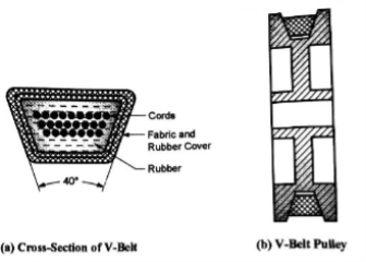
Figure: V – Belt Cross Section and Pulley
- Normally included angle of V belt is 40° while for grooved pulley angle is 38°. Due to wedging action, they can transmit large power when two pulleys are relatively close to each other.
Advantages of V - Belt Drive:
1) Due to wedging action, they transmit large power as compared to flat belt drive and also Due to wedging action, slip is less.
2) Used for short centre distance which results in compact construction.
3) With multiple drive, V belt can transmit very large power.
4) They permit high speed ratio (reduction ratio) even upto 7.
5) V belts are endless (has no joint), so the operation is smooth and quiet even at very high speed.
Limitations of V Belt Drive:
1) Efficiency of V-belt is less as compared to flat belt drive. It is in the range of 80 % to 96 %.
2) They cannot transmit power over long centre distance.
3) They are costly as compared to flat belt drive.
Applications of V Belt Drive:
1) V belts are used to drive Pump, Air Compressor, machine tools, Farm Machinery and automobile engine accessories.
3. Timing Belt:
- Timing belt is toothed belt transmit the power by teeth rather than friction hence there will be no slip.
- Timing belts require toothed wheel or sprockets.
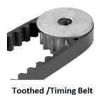
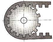
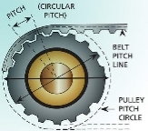
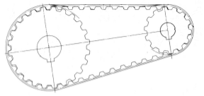
Figure: Timing Belt
Limitations of timing Belt:
1) They cannot transmit large power.
2) They are costly.
Comparison between Flat belt and V - belt drive
Sr. No. | Parameter | Flat Belt Drive | V – Belt Drive |
1 | Cross Section | Rectangular | Trapezoidal |
2 | Joint | Flat belt have joint. | V belts are joint-less / endless. |
3 | Construction of Pulley | Require Flat Pulley with simple construction. | Require V grooved pulley which has complicated construction. |
4 | Centre Distances | Flat belt drives are used to transmit power over long distances upto 15 meter. | V - Belt drives are used to transmit power over short centre distances upto 3 meter. |
5 | Slip | Slip is more. | Slip is less due to wedging action. |
6 | Power Transmission | Not useful for large power transmission. | Due to wedging action, useful for large power transmission. |
7 | Operating Speed | Not useful for high speed application. | Can be used for high speed application. |
8 | Speed ratio | Not useful for high speed ratio.(Limited Upto 3to 4) | Can be used for high speed ratio.(Upto 7) |
9 | Efficiency | High (Upto 98%) | Low (80% - 96%) |
10 | Operation | Noisy Operation | Smooth & Quite Operation. |
11 | Cost | Cheaper | Costlier. |
The conveyor arrangement uses the following types of pulleys
- Driving Pulley (Head and Tail pulley)
- Snub Pulley
- Idlers
Driving pulley (Head and Tail pulley)
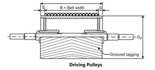
- Drive pulley is located at the discharge terminal of the conveyor. It provides driving force for the conveyor. In order to increase pulley life and traction, it often has larger diameter than other pulleys.
- They are manufactured in a wide range of size and consist of a continuous rim and two end discs fitted in the hub. The rim is supported by stiffening discs welded to it to support large loads.
- The pulley may be straight faced or crowned due to such arrangements the crown helps in keeping the belt cantered
- Crown height is 0.5% of pulley width and not less than 4 mm.
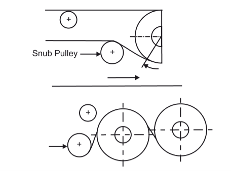
Snub Pulley
These are used to increase the angle of wrap of the belt and overall for all the necessary changes in belt direction in the areas of counterweight tensioner, mobile unloader etc.
The choice of the optimum conveyor system and its project design and rationalization depends on full knowledge of the construction characteristics and the forces involved that apply themselves to all the system components.
Idlers
The efficiency of belt conveyor is mainly dependent on idlers. For higher efficiency of conveying systems, the idlers must be accurately made and provide a rigid framework. This will maintain a permanent, well balanced smooth running alignment.
There are, in general, three kinds of belt carrying idlers used in handling of bulk materials. The type of idlers affects the cross-sectional load on the belt.
- Flat belt idlers: are used for granular materials having an angle of repose of not less than 35°. Flat belt idlers are preferred for low capacity requirements.
- Toughing idlers with 20° through: are used for conveying all kinds of bulk materials.
- Troughing idlers with 35° and 45° through: are used for transportation of small particles and lightweight materials like grain, cotton seed etc.
There are two basic types of belt conveyor idlers:
Carrying idlers which support the loaded run of the conveyor belt; and
Return idlers which support empty return run of the conveyor belt.
Carrying Idlers
- Usually troughed with 3 equal size rollers on a frame in mining applications
- Some suspended catenary systems have 5 rollers
- Toughing angles are usually 20, 35, 45 degrees
- Deeper trough more volume
- Requires thinner belt to lay in trough which limits strength.
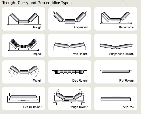
Return Idlers
- Usually Flat and one piece
- Sometimes two-piece V for belt training
- Spiral roll to self and belt clean
- Rollers
Selection of Flat and V-belts from manufacturer’s catalogue
In practice, the designer has to select a belt from the manufacturer’s catalogue. For the selection of a proper belt for a given application, the following information is required:
(i) Power to be transmitted;
(ii) The input and the output speeds;
(iii) Thecentre distance depending upon the availability of space; and
(iv) Type of load.
The basic procedure for belt selection from the catalogue of The Dunlop Rubber Co. (India) Ltd. Is discussed in this section. The basic procedure for selection of fl at belt consists of the following steps:
(i) The optimum belt velocity of Dunlop belts is from 17.8 to 22.9 m/s. Assume some belt velocity such as 18 m/s in this range and calculate the diameter of the smaller pulley by the following relationship:
d = 60(1000)v/πn
Where n is the input speed or rpm of thesmaller pulley.
The diameter of the bigger pulley is obtained by the following relationship:

Modify the values of d and D to the nearest preferred diameters. Determine the correct belt velocity for these preferred pulley diameters and check whether the actual velocity is in the range of optimum belt velocity. The preferred diameters (in mm) of cast iron and mild steel pulleys are as follows:
100, 112, 125, 140, 160, 180, 200, 224, 250, 280, 315, 355, 400, 450, 500, 560, 630, 710, 800, 900 and 1000
(ii) Determine the load correction factor Fa from Table 5.1. It depends upon the type of load. Find out the maximum power for the purpose of belt selection by following relationship,
(kW)max. = Fa (kW)
Table Load correction factor (Fa)


(iii) Calculate the angle of wrap for the smaller pulley by the following relationship:

Find out the arc of contact factor Fdfrom Table.
Table Arc of contact factor (Fd)

(iv) Calculate the corrected power by the following relationship:
(kW)corrected = (kW)max. * Fd
(v) Calculate the corrected power rating for the belt by the following relationships:

Where v is the correct belt velocity in m/s.
(vi) Calculate the product of (width * number of plies) by dividing the corrected power by the corrected kW rating. Or,

Calculate the belt width by assuming a suitable number of plies. In this step, there are a number alternative solutions. A belt whose width is near the value of the standard width is the optimum solution. For this belt, select the standard belt width. The standard widths of these belts (in mm) are as follows:


(vii) Calculate the belt length by using the following relationship:

The above procedure of belt selection is explained in Example 5.1
Example It is required to select a flat belt drive for a compressor running at 720 rpm, which is driven by a 25 kW, 1440 rpm motor. Space is available for a centre distance of 3 m. The belt is open-type.
Solution Given kW=25, n1=1400rpm, n2=720, C=3m
Step I: Diameter of smaller and bigger pulleys
d = 60(1000)v/πn
Using a belt velocity of 18 m/s,
d = 60(1000)v/πn1 = 60(1000)*18/π*1440 = 238.73 mm
Selecting the preferred pulley diameter of 250 mm, (refer preferred diameters of pulleys in step i)
d = 250 mm and D = 2 * 250 = 500 mm
The belt velocity for these dimensions is given by,
v = πdn1/60(1000) = π*250*1440/60(1000) = 18.85m/s
Step II Maximum power for selection
From Table, the load correction factor for the compressor is 1.3. Therefore,
Maximum power = 1.3(25) = 32.5 kW
Step III Arc of contact factor (Fd)


Assuming linear interpolation, the arc of contact factor is given by,


Step IV Corrected power
Corrected power = 1.019(32.5) = 33.12 kW
Step V Corrected power rating of belt
Selecting a HI-SPEED belt, the corrected rating at a belt speed of 18.85 m/s is given by,
Step VI Selection of belt


Belt widths,
We shall select a HI-SPEED belt of 152 mm preferred width and 5 plies. (Refer step vi)
Step VII Belt length
The belt length is given by,


Thus, Belt Specification 7.2 m length of 152 mm width and 5 plies HI-SPEED belting.
References:
1. Shigley J., Mischke C., Budynas R. And Nisbett K., Mechanical Engineering Design, 8thed., Tata McGraw Hill,2010.
2. Jindal U.C., Machine Design: Design of Transmission System, Dorling Kindersley,2010.
3. Maitra G. And Prasad L., Handbook of Mechanical Design, 2nd ed., Tata McGraw Hill,2001.