Unit - 2
Gear transmission
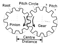
- Gears are defined as the toothed wheels which can transmit power and motion from one shaft to another shaft by means of successive engagement of teeth.
- Gears operate in pairs, the smaller is called pinion and the larger is called Gear. They always rotate in opposite direction. Gear tooth profile is either involute or cycloid.
- In precision machines and mechanisms like watch gear mechanism, definite speed ratio is required which is obtained by using gear drive or gear wheels.
- Gear drive is a positive drive and it is used when the distance between the driver and follower is very small.
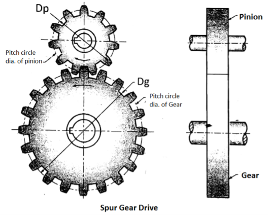
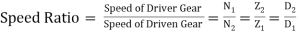
- Speed Ratio (Gear Ratio) of gear drive is the ratio of Speed of Driving Gear to the Speed of Driven Gear. It is also defined as ratio of number of teeth Gear to the number of teeth on the Pinion.
 Where,
 - N1 = Speed of Driver Gear in (RPM)
- N2 = Speed of Driven Gear in (RPM)
- D1 = Diameter or Pitch Circle Diameter (PCD) of Driver Gear
- D2= Diameter or Pitch Circle Diameter (PCD) of Driven Gear
- Z1 = No. Of Teeth on Driver Gear
- Z2 = No. Of Teeth on Driven Gear
Pitch Line Velocity of Gear and pinion:
The pinion and gear rolls over each other, without slipping, along the pitch circle. Hence pitch line velocity of pinion and gear is same.
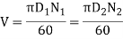
∴ Np Dp = Ng Dg

 Where,
- V= pitch line velocity, mm/sec or m/sec
- Dp= diameter or pitch circle diameter of pinion, mm or m
- Dg = diameter or pitch circle diameter of gear, mm or m
- Np= pinion speed,rpm
- Ng = gear speed, rpm
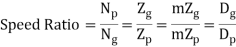
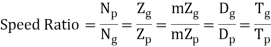
Speed Ratio or Gear Ratio:
It is the ratio of the pinion speed to gear speed. OR ratio of number of teeth on gear to number of teeth on pinion.
- Zp= number of teeth on pinion
- Zg= number of teeth on gear
- m = module, mm
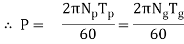
Power Transmission Capacity of Gear Drive:
The efficiency of all gear drives is about80% but in actual practice it is assumed as 100%. Hence power of pinion and gear is same.
Let,
- P = power transmitted, Watt
- Tp= torque on pinion, N-m
- Tg=torque on gear, N-m


In designing a gear, it is important to analyze the magnitude and direction of the forces acting upon the gear teeth, shafts, bearings, etc. In analyzing these forces, an idealized assumption is made that the tooth forces are acting upon the central part of the tooth flank.
Table 1 presents the equations for tangential (circumferential) force Ft (kgf), axial (thrust) force Fx(kgf), and radial force Fr in relation to the transmission force Fn acting upon the central part of the tooh flank. T and T1 shown therein represent input torque (kgf·m).
Table.1 Forces acting upon a gear
Types of gears | F1 : Tangential force | F1 : Axial force | F1 : Radial force | |
Spur gear |  | --------- | F1 tan α | |
Helical gear | F1 tan β |  | ||
Straight bevel gear |    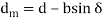 | F1 tan α sin δ | F1 tan α cos δ | |
Spiral bevel gear | When convex surface is working | |||
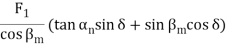 |  | |||
When concave surface is working | ||||
 | 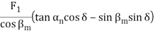 | |||
Worm gear pair | Worm (Driver) |  | 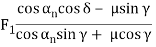 | 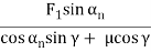 |
|  | F1 | ||
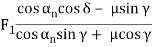
Screw gear(∑ = 90o β = 45o) | Driver gear |  | 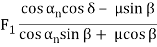 | 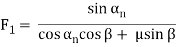 |
Driven gear | 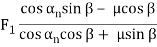 | F1 | ||
Load as

Factor of safety: It is defined as ratio of maximum stress to working stress
Mathematically FOS =
For Ductile material, FOS = 
For brittle material, FOS =
Typical values
Application | FOS |
Aircraft components | 1.5-2.5 |
Bolts | 8.5 |
Pressure vessels | 3.5-6 |
Reliable material , normal condition | 1.3-1.5 |
Ordinary material , normal condition | 2-2.5 |
Unreliable material , severe condition | 3-4 |
Importance of FOS
- There is variation in properties of material like yield strength, ultimate strength
- Uncertainty in variation of external loads and forces
- Variation in dimension of component due to lack of workmanship
- To ensure safety of component from above mentioned variation and uncertainty, Factor of Safety is useful in Design
Key Takeaway:
- FOS is important for design safer and reliable component, higher the uncertainty regarding material and external forces higher the FOS for safer Design
Factors on which selection of gear material depends are:
- Type of service
- Degree of the desired accuracy
- Required dimensions and weight of the drive
- Peripheral speed
- Method of manufacturing
- Allowable stress
- Wear resistance
- Shock resistance
Force analysis of helical gear
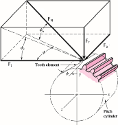
Figure. Forces on helical gear tooth
The resultant force P acting on the tooth of a helical gear is resolved into three components, Pt, Pr and Pa as shown in Fig. 2.4, where
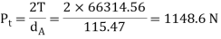
Pt = tangential component (N)
Pr = radial component (N)
Pa = axial or thrust component (N)
Force | Expression |
Tangential force (Pt) |  |
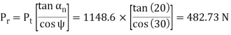
Radial force (Pr) | 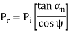 |
Axial or thrust force (Pa) |  |
Table. Forces on helical gear tooth
Where,
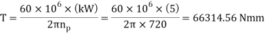
T = torque transmitted by gears (N-mm)
KW = power transmitted by gears (kW)
np = speed of rotation of pinion (rpm)
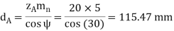
dp= pitch circle diameter pinion (mm).
Example A pair of parallel helical gears is shown in figure. A 5 kW power at 720 rpm is supplied to the pinion A through its shaft. The normal module is 5 mm and the normal pressure angle is 20°. The pinion has right-hand teeth, while the gear has left-hand teeth. The helix angle is 30°. The pinion rotates in the clockwise direction when seen from the left side of the page. Determine the components of the tooth force and draw a free-body diagram showing the forces acting on the pinion and the gear.
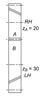
Solution
Given, kW = 5, nA = 720 rpm,zA = 20, zB = 30, mn= 5 mm
ψ = 30°, αn = 20°.

Free body diagram of forces is shown in following figure
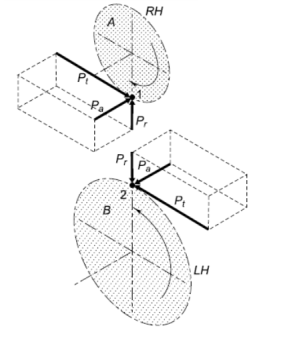
Fig. Free body diagram of forces
References:
1. Shigley J., Mischke C., Budynas R. And Nisbett K., Mechanical Engineering Design, 8thed., Tata McGraw Hill,2010.
2. Jindal U.C., Machine Design: Design of Transmission System, Dorling Kindersley,2010.
3. Maitra G. And Prasad L., Handbook of Mechanical Design, 2nd ed., Tata McGraw Hill,2001.


