Unit - 4
Gear box
- Gear box receives the power from engine through clutch and transmits the power to the propeller shaft
- In gear box torque is increased and speed is reduced. Great box produces different speed ranges for the vehicle.
Need of Geer Box in Vehicles:
- In automobile vehicle the I.C. Engine operates at high speed but the torque produced by I.C. Engine is not very high.
- If I.C. Engine is directly connected to the wheels, the engine torque may not be enough to drive the vehicle.
- The gear box receives the power form engine at high speed. It reduces the speed and increases the torque, which is adequate to drive the vehicle.
- I.C. Engines operate over limited speed range. However, automobile vehicle has to run over the wide range of speeds and torque. The gear box provides wide range of speeds and torque to the vehicle.
Functions of Gear Box:
- Gear box reduces the speed and increases the torque.
- Gear box provides wide range of speeds and torque to the vehicle.
- With reverse gear, gear box provides the means to move the vehicle in reverse direction.
- In neutral position, the gear box disconnects the I.C. Engine from the wheel even with the clutch in the engaged position.
Types of Gear Box
- Sliding Mesh type gear box
- Constant Mesh type gear box
- Synchro Mesh type gear box
In different words, the ray diagram is a graphical illustration of the structural formula, as proven in figure.
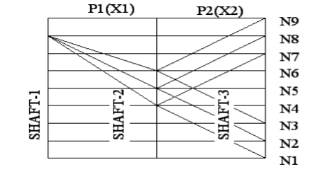
This is the graphical illustration of power arrangement & this offers the following information:
- No. Of stages
- No. Of speeds in every stage
- Values of transmission ratio
Principles to be followed to obtain Optimum Design:
To avoid excessively large diagram of beam & to limit the pitch line velocity of gear,
- In optics a ray is an idealized geometrical version of mild, acquired with the aid of using selecting a curve this is perpendicular to the wave fronts of the real mild, and that factors with inside the course of strength flow.
- Rays are used to version the propagation of mild via an optical device, with the aid of using dividing the actual mild discipline up into discrete rays that may be computationally propagated via the device with the aid of using the strategies of ray tracing.
- This permits even very complicated optical structures to be analyzed mathematically or simulated with the aid of using computer.
- Ray tracing makes use of approximate answers to Maxwell's equations which are legitimate so long as the mild waves propagate via and round items whose dimensions are tons more than the mild's wavelength.
- Ray optics or geometrical optics does now no longer describe phenomena consisting of diffraction, which require wave optics theory. Some wave phenomena consisting of interference may be modeled in constrained instances with the aid of using including section to the ray version.
1. No. Of gears on the last shaft must be minimum.
2. No. Of gears on any shaft should not be more than 3.
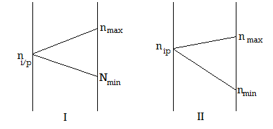
3. It is preferable to have nmax ≥ ninput ≥ nmin in every stage except first stage.
4. The transmission ratio 
5. The ratio 
6. Never keep the ratio 
Symbolically this condition is represented by
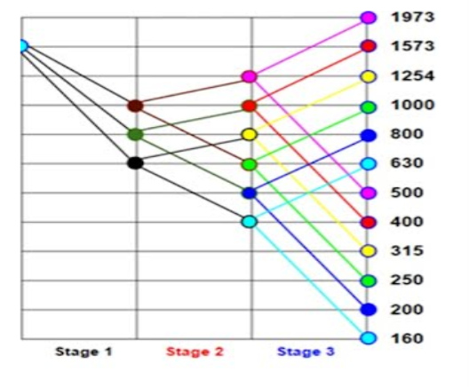
It offers the subsequent records at the drive:
- The quantity of stages (a level is a fixed of tools trains organized on consecutive shafts)
- The quantity of speeds in every level.
- The overall quantity of speeds to be had on the spindle.
Procedure
In this diagram, shafts are proven through vertical equidistant and parallel traces.
Transmission engaged at precise speeds of the riding and pushed shafts are proven at the diagram through rays connecting the factors at the shaft traces representing these speeds.
Figure indicates the ray diagram for a nine velocity tools box, having the structural formula, z = 3 (1). 3 (3)
Since there are 4shafts, draw four vertical equidistant traces to symbolize shafts.
Since there are 12 spindle speeds, draw 12 horizontal equidistant traces.
From the structural formula, its miles clean that there are stages. In the 0.33 level, i.e., in 2 (6), 2 represents the wide variety of speeds to be had in that level and (6) represents the steps or periods among those speeds.
Locate the primary factor A on the bottom velocity i.e., at a hundred and sixty r.p.m. At the ultimate shaft. After 6 steps above, find the second one factor B at 630 r.p.m. These are the 2 output speeds.
Locate the enter velocity at any factor at the previous shaft (i.e., shaft 2), assembly the ratio requirements. We find, the enter velocity four hundred r.p.m. At factor C satisfies the ratio requirements. In the second one level, there are speeds. Lowest is at C, that's already positioned. Now find factor D at the third shaft, above factor C, in a 3 step interval. For those output speeds within side the 2nd level, the entire ought to be from shaft 2. We find, the enter velocity 630 r.p.m.
In the primary level, there speeds. Lowest velocity is at E, that's already positioned. Now find factors F and G at the shaft 2, above factor E, in a unmarried step interval.
Input velocity may be positioned everywhere on shaft 1 assembly the ratio requirements. But in this problem, given that, enter velocity is at 1600 r.p.m.
In level 2, we discover enter velocity at E offers output speeds at C and D. Similarly, enter speeds at F and G, ought to provide output speeds. This may be performed via way of means of drawing traces parallel to EC and ED, from factors F and G, as proven in figure
Now for level 3, to get the output speeds to all of the enter speeds in shaft 3, draw traces parallel to CA and CB. Thus we've positioned all of the entire and the output speeds. The finished ray diagram is proven in figure
Stage 3:


Stage 2:


Stage 1:


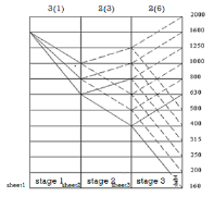
Ratio requirements are satisfied.
Selection of optical Ray Diagram:
BASIC RULES FOR OPTIMUM GEAR BOX DESIGN
The basic rules to be followed while designing the gear boxes are as follows:
1. The transmission ratio (i) in a gear box is limited by

Refer the figure
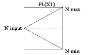
In other words,


2. For stable operation, the speed ratio at any stage should not be greater than 8. In other words,
3. In all stages except in the first stage, NmaxNinputNmin
4. The sum of teeth of mating gears in a given stage must be the same for same module in a sliding gear set.
5. The minimum number of teeth on smallest gear in drives should be greater than or equal to 17.
6. The minimum difference between the number of teeth of adjacent gears must be 4.
7. Gear box should be of minimum possible size. Both radial as well as axial dimensions should be as small as possible.
Key Takeaways:
- The quantity of speeds in every level.
- In the primary level, there speeds. Lowest velocity is at E, that's already positioned. Now find factors F and G at the shaft 2, above factor E, in a unmarried step interval.
The kinematic arrangement of a multi – speed gear box is shown in figure.
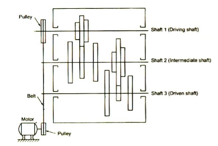
From the figure, it is clear that the kinematic layout shows the arrangement of gears in a gear box. The kinematic layout provides the following information’s required for gear box design.
- The number of speeds available at the spindle, i.e., at the driven shaft.
- The number of stages used to achieve the required spindle speeds.
- The number of simple gear trains required to obtain the required spindle speeds and their arrangement.
- The overall working principle of the gear box.
- The information required for structural formula and ray diagram.
CONSTANT MESH GEAR BOX
- Components of Constant Mesh Gear Box are:
- Input Shaft (Clutch Shaft)
- Output Shaft (Main Shaft)
- Lay Shaft (Counter Shaft)
- Gears (A1, A2, B1, B2, C1, C2, D1, D2)
- Dog Clutches (S1, S2)
- Gear Shifting Mechanism
- Input Shaft (Clutch Shaft):
- The input shaft of gear box is connected to the engine through clutch. It receives the power at high speed and low torque) from the engine.
- Output Shaft (Main Shaft):
- The output shaft of the gear box is connected to the propeller shaft through the universal joint. It transmits power (at low speed and high torque) to the propeller shaft. It is a splined shaft.
- The gears B1, C1 and D1 are free to rotate on this shaft. The dog clutches S1 and S2 can slide axially on this shaft.
- Lay Shaft (Counter shaft):
- The lay shaft is a shaft parallel to input and output shafts. The gears A2, B2, C2 and D2 are rigidly mounted on it.
- Gears:
- Gear A1 is mounted on input shaft and it is constantly in engagement with gear A2 mounted on the lay shaft.
- Gears A2, B2, C2 and D2 are rigidly mounted on the lay shaft.
- Gears B1, C1 and D1 are free to rotate on splined output shaft.
- Dog Clutches:
- The dog clutches S1 and S2 are free to slide axially on splined shaft. The dog clutch S1 can engage with gear A1 orgear B1.
- Similarly the dog clutch S2 can engage with gear C1 or gear D1.
- Gear Shifting Mechanism:
- The gear shifting mechanism is operated by gear lever to shift or change the gears.
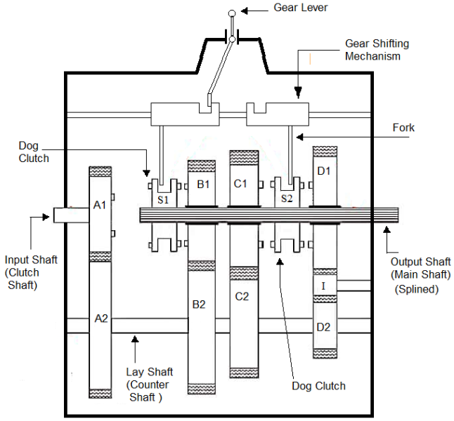
Figure: Constant Mesh Gear Box
Working of Constant mesh Gear Box
- In this type of gearbox, all the gears of the main shaft are in constant mesh with corresponding gears of the countershaft.
- The gears on the main shaft which are bushed are free to rotate. The dog clutches are provided on main shaft. The gears on the lay shaft are, however, fixed.
- When the left Dog clutch is slid to the left by means of the selector mechanism, its teeth are engaged with those on the clutch gear and we get the direct gear.
- The same dog clutch, however, when slid to right makes contact with the second gear and second gear is obtained.
- Similarly movement of the right dog clutch to the left results in low gear and towards right in reverse gear.Usually the helical gears are used inconstant mesh gearbox for smooth and noiseless operation.
1st gear :
- To engage 1stgear, dog clutch S2 is shifted to left to engage with gear C1.
- Power flow: Input Shaft - Gear A1- Gear A2- Lay Shaft - Gear C2 - Gear C1 — Dog Clutch S1- Output Shaft.
2nd Gear:
- To engage 2ndgear, dog clutch S2 is shifted to right to disengage from gear C1 and dog clutch S1 is shifted to right to engage with gear B1.
- Power flow: Input Shaft - Gear A1- Gear A2- Lay Shaft - Gear B1 - Gear B2- Dog Clutch S1 - Output Shaft.
3rd gear :
- To engage 3rd gear, dog clutch S1 is shifted to left to engage with gear A1.
- Power flow: Input Shaft - Gear A1 — Dog Clutch S1- Output Shaft.
Reverse Gear :
- To engage reverse gear, dog clutch S1 is shifted to right to disengaged from gear A1 and dog clutch S2 is shifted to right to engage with gear D1.
Gear ratio (speed ratio) of gear box:
- Gear ratio speed ratio of gear box is the ratio of speed of input shaft (engine shaft) to the speed of output shaft (propeller shaft).
- Let,
- Ni = speed of input shaft of gear box (r.p.m.)
- No = speed of output shaft of gear box (r.p.m.)
- I = gear ratio or speed ratio

- The gear ratio (speed ratio) of gear box is different in different gears. It is maximum in 1st gear and minimum in last gear.
Power Transmission Capacity of Gear Box:
Let,
- Pi= input power to gear box (engine power), Watt
- Po = output power of gear box (propeller shaft power), Watt
- Ti = input torque to gear box (enginetorque), N-m
- To output torque of gear box, (propeller shaft torque), N-m
Input power


Output power


Efficiency of Gear Box
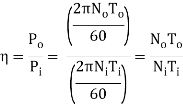
If Efficiency of Gear Box is 100 %, i.e. η = 1, then
∴ NoTo = Ni Ti
∴ Output speed × Output torque = Iput speed × input torque
References:
1. Shigley J., Mischke C., Budynas R. And Nisbett K., Mechanical Engineering Design, 8thed., Tata McGraw Hill,2010.
2. Jindal U.C., Machine Design: Design of Transmission System, Dorling Kindersley,2010.
3. Maitra G. And Prasad L., Handbook of Mechanical Design, 2nd ed., Tata McGraw Hill,2001.