Unit - 5
Flexible transmission elements
Types of cams
Cams can be classified based on their physical shape.
a) Disk or plate cam: The disk (or plate) cam has an associate degree irregular contour to impart a selected motion to the follower. The follower moves in an exceedingly plane perpendicular to the axis of rotation of the camshaft and is a command in grips with the cam by springs or gravity.
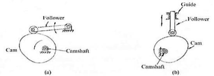
Figure. Disk or Plate Cam
b) Cylindrical cam: The cylindrical cam contains a groove cut on its cylindrical surface. The roller follows the groove, and therefore the follower moves during a plane parallel to the axis of rotation of the cylinder.
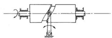
Figure. Cylindrical Cam
c) Translating cam: The translating cam may be a contoured or grooved plate slippery on a guiding surface(s). The follower could oscillate (Fig. a) or reciprocate (Fig. b). The contour or the form of the groove is decided by the desired motion of the follower.

Figure. Translating Cam
The undercut of gears is likewise referred to as deeper reducing and shows the phenomenon of reducing the basis of the tools deeper than the involute teeth curve. This can occur while there's interference among a teeth reducing device and a tools or among the 2 meshing gears.
When the undercutting is large, the basis of the tools will become narrower and the teeth shape will become vulnerable in its bending strength. The principal cause for undercutting to arise is, while reducing a tools with a small variety of enamel (for trendy tools with 20° stress attitude, variety of enamel z = 17 or less), the end of the reducing device is going past the interference point.
Profile transferring way converting the intensity of the reducing device and with inside the case of undercut, a wonderful profile shift is used. In this case, the basis of the tools teeth will become thicker. There is a restriction to the quantity of wonderful profile shift, and warning need to be exercised on the grounds that while the shift is excessive (x = +0.5), the end of the teeth will become pointed. In addition, the examples of tools terminology associated with undercut are involute teeth shape, profile shifted tools, wonderful profile shift, etc.
Pressure attitude: It is the attitude which the road of movement makes with the not unusual place tangent to pitch circles of mating gears OR Simply refers back to the attitude via which forces are transmitted among meshing gears.
Significance:
1) Growing stress attitude improves the teeth strength.
2) Growing stress attitude bring about smaller base circle so greater part of teeth will become involute for that reason can cast off interference.
3) Growing stress attitude will enhance strength transmission however on the equal time will boom tools put on and meshing noise
4) Lowering the stress Angle would require greater enamel at the pinion to keep away from undercutting
5) Low stress attitude will lower strength transmission capability however will enhance tools meashing homes like decreased noise.
Ideally 20° of stress attitude (involute system) is desired because It reduces chance of undercut, reduces interference, because of improved stress attitude as compared to 14.5°, the teeth will become barely broader at the basis. This makes teeth more potent and will increase load sporting capability. Conversely for 14.5° stress attitude tools offers quietness of operation.
Single Plate Clutch:
Single plate clutch is mainly used in lightweight vehicles for transmitting torque from an engine to the input shaft. As per the name of this Clutch it just has a single Clutch plate.
Working Of Single Plate Clutch
When the engine is walking and consequently the flywheel is rotating, the strain plate additionally rotates due to the fact the strain plate attaches to the flywheel. The friction disc is positioned among the flywheel and the strain plate. When the using pressure has driven down the take hold of is released. The strain plate is bolted to the flywheel via take hold of springs and is loose to slide (Move) at the take hold of shaft while the take hold of pedal is operated (Engage and Disengage).
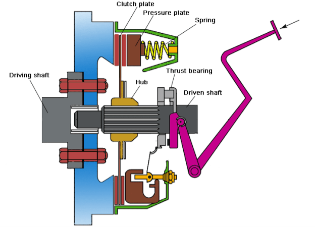
Multi plate Clutch:
This kind of take hold of has a couple of take hold of plates which can be used to transmit electricity from the shaft of an engine to the transmission shaft of the equal vehicle. It is split into subdivisions additionally, they're moist take hold of and dry take hold of. Here is a Cool Video on Wet and Dry take hold of [External Link]! A take hold of while operates inside an oil tub then it's far known as a moist take hold of. On the opposite hand, a dry take hold of operates without oil.
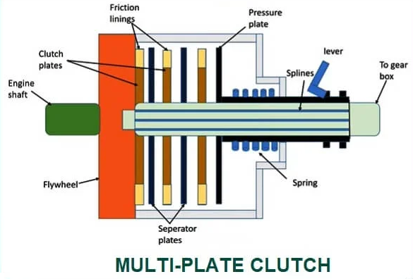
Working of Multi plate clutch:
1. When snatch is engaged:
During the engaged function of the snatch, i.e., whilst the snatch pedal isn't pressed. The thrust springs do now no longer flow because of which the stiffness supplied through those springs continues the stress over the stress, the plate having friction traces on its internal surface. Due to this stress over the stress surface, the frictional touch among the friction traces of the stress plate and the friction traces of a couple of snatch plates is maintained because of which frictional pressure is implemented over the flywheel. Due to this frictional pressure, the frictional touch among the numerous snatch plates and the wheel is supported, which in flip sooner or later affords snatch engagement.
2. When snatch is disengaged:
When the snatch pedal is pressed, the fulcrum connected at its internal stop rotates because of which the internal splined sleeve thru which the stress plate connects movements outward, which in flip applies stress over the thrust springs. Due to this pressure, the thrust springs flow, which in flip releases the anxiety over the stress plate, and sooner or later, the frictional pressure among the stress plate, snatch plate, and the flywheel is removed. For the motive that the elimination of the frictional pressure, frictional touch among the stress plate, snatch plate, and flywheel breaks and sooner or later the disengagement of the snatch obtained.
Cone Clutch is a type of frictional capture. It is used to engage and disengage engine shaft to the transmission discipline shaft even as changing equipment ratio. Cone capture makes use of conical surfaces to transmit torque with the useful resource of the use of friction.
Cone capture is much less complex to engage and disengage in comparison to a pleasant displacement capture which modified into used in advance than cone clutches have been invented. Higher torque can be transferred using the cone capture than same period of plate capture due to greater contact area. The driving shaft and the driven shaft want to be perfectly coaxial for inexperienced functioning of the capture. This capture can be used wherein immoderate torque transmission is wanted at low rotating speed. So, this type of capture is extensively is heavy vehicles.
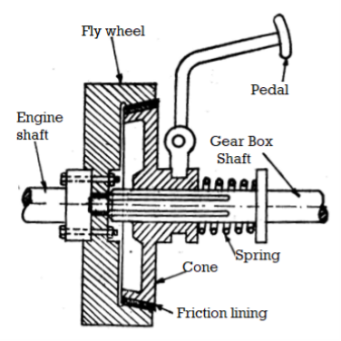
Fig. Cone Clutch
Parts of Cone Clutch:
1. Female Cone or Outer Cone:
It is the part of the cone grasp this is linked to the flywheel of the engine and additionally rotates with it. This component identity notification continually in rotating circumstance because the engine shaft rotates continuously. Female cone has internal slicing cone-fashioned groove which has friction lining over which the male cone interlocks and make frictional touch with it in an effort to have interaction the drive. This lady cone is installed over stable shaft.
2. Male Cone or Inner Cone:
This cone is hooked up to the transmission device or the gearbox. Inner cone has friction lining with inside the outer component which creates frictional touch with internal friction lining of the outer cone. By default, internal cone stays in touch with the outer cone with the assist of strain springs that is located at the back of the internal cone. When the grasp pedal is pressed in situations like converting gear, the spring is compressed and the internal cone actions far from the outer cone and disengages from the outer cone and consequently the engine is disengaged from the transmission box. This internal cone has internal splines and actions over slices of shaft for to and from motion.
3. Springs:
Springs are positioned in the back of the male cone which can be used to hold the internal cone engaged with outer cone. When the seize pedal is pressed, the spring compresses and the internal cone disengages with outer cone and consequently the driving shaft is disconnected from pushed shaft.
4. Sleeves:
Sleeves are the part of the seize that is connected to the male cone and installed at the splines and those sleeves are used for back and forth movement of male cone.
5. Pedal:
A seize pedal is used to function the seize.
Working:
By default, the male cone is engaged with the woman cone because of the strain of the spring that's gift at the back of the male cone. When the take hold of pedal is pressed so that it will extrude the tools or for a few different cause, the fulcrum that's connected to pedal rotates which in flip compresses the spring and additionally the male cone is pulled far from the woman cone. Thus the touch among the male cone and woman cone will break.
So, the engine shaft may be disengaged from transmission device and rotation of engine shaft or using shaft will now no longer be transferred to the transmission shaft or the pushed shaft. Now after the disengagement whilst the take hold of pedal is launched slowly with the aid of using the motive force after converting the gears, the fulcrum that's connected to the pedal rotates and the spring expands and the male cone begins off evolved transferring closer to the woman cone over splines.
After that, the male take hold of make touch with the woman take hold of and friction pressure act among the internal friction lining of outer cone and outer friction lining of internal cone. Now the cone take hold of is stated to be in have interaction role and the rotation of engine shaft or using shaft is transferred to the transmission shaft or pushed shaft and each the shaft begin rotating at equal speed. The stiffness with the aid of using the spring continues the male cone and woman cone of the cone take hold of in engaged role.
Advantages:
1) The ordinary pressure performing on touch floor is more than the axial pressure.
2) Higher torque may be transferred than the identical length of plate grab because of huge quantity of frictional pressure involved.
3) It creates much less noise than plate grab.
4) Less put on and tear compared to displacement grab.
Applications:
For smooth disengagement, the cone perspective must be precisely as required.
1) Cone clutches are utilized in heavy motors as they could transmit excessive torque.
3) Cone snatch is likewise utilized in excessive off-street motors.
4) It is likewise utilized in low peripheral velocity applications.
5) It is likewise used as a synchronizer in diverse guide transmissions.
Key Takeaways:
- Cone capture makes use of conical surfaces to transmit torque with the useful resource of the use of friction.
- It is the part of the cone grasp this is linked to the flywheel of the engine and additionally rotates with it.
- By default, the male cone is engaged with the woman cone because of the strain of the spring that's gift at the back of the male cone.
- The working precept of the actuator of electromagnetic snatch is an electromagnetic effect, however torque transmission is mechanical.
- The distinction among electromagnetic snatch and the everyday snatch is in how they manipulate the motion of strain plates.
- In the ordinary snatch, a spring used to interact the snatch while in EM snatch an electromagnetic area is used for engagement.
- The electromagnetic snatch comes numerous forms, such as magnetic particle snatch and multi-disc snatch.
- There are even no-touch clutches which include hysteresis snatch and eddy cutting-edge snatch. However, maximum broadly used shape is unmarried face friction snatch.
Construction:
Rotor:
Rotor is a primary a part of this snatch witch is hooked up at once to the riding shaft or engine shaft. It constantly rotate alongside the riding shaft.
Winding or Coil:
Winding coil is located at the back of the rotor and stays in desk bound function for the duration of snatch working. It is proven in figure. A excessive voltage DC deliver is hooked up with this winding which switch a excessive voltage present day into this winding and convert it into electromagnet.
Armature:
Armature is located at the front of the rotor. It is hooked up to the hub or stress plated with the assist or rivet or bolted joint.
Hub:
Hub or stress plate is bolted with the tools shaft or pushed shaft and rotates with it. It is located after the armature.
Friction Plate:
Friction plate is inserted among armature and rotor in keeping with the requirement.
Supply unit:
Supply unit consist snatch switch, battery, cord etc.
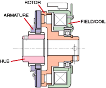
Fig: Electromagnetic Clutch
Working of electromagnetic clutch
- The predominant additives of EM take hold of are a coil shell, an armature, rotor, and hub.
- The armature plate is covered with friction coating. The coil is positioned at the back of the rotor.
- When the take hold of activated the electrical circuit energizes the coil, it generates a magnetic area. The rotor part of take hold of receives magnetized.
- When the magnetic area exceeds the air hole among rotor and armature after which it pulls the armature towards the rotor. The frictional pressure generated on the touch floor switch the torque.
- Engagement time relies upon at the electricity of magnetic fields, inertia, and air hole. When voltage is eliminated from the coil, the touch is gone.
Key Takeaways:
- The electromagnetic snatch comes numerous forms, such as magnetic particle snatch and multi-disc snatch.
- Friction plate is inserted among armature and rotor in keeping with the requirement.
- The frictional pressure generated on the touch floor switch the torque.
Brake
Brake is a device used for device for slowing or to control its speed to a certain value under varying conditions or stopping a vehicle or other moving mechanism by the absorption or transfer of the energy of momentum, usually by means of friction.
Where brakes are used?
The usual answer is in a car or a vehicle where safe, fast and smooth stopping when required or simply when there is a need to stop at a stop sign or in a driveway. And not always brakes are used to bring the vehicle to a full stop. For slowing down in traffic or to turn round a curve requires braking to decrease the speed from a higher to a lower speed.
Brake is also used in elevators, escalators, hoists, and winches, which must stop and hold a load after lifting it. Also, in machine tools, conveyors, and other manufacturing equipment must often be brought to a safe, quick stop employs brakes.
Classification of Brakes
- Drum brakes
- Band brake
- Cone brake
- Disk or axial brake
Drum Brakes
Drum brakes apply friction to the external or internal circumference of a cylinder. A drum brake consists of the brake shoe, which has the friction material bonded to it, and the brake drum. For braking, the shoe is forced against the drum developing the friction torque. Drum brakes can be divided into two groups depending on whether the brake shoe is external or internal to the drum.
1. Internally expanding shoes
2. Externally contracting shoes
Internal expanding shoe brake
Most drum brakes use internal shoes that expand against the inner radius of the drum with brake lining. Internal drum brakes are used in automotive applications. A drum brake consists of two brake shoes and linings supported on a back plate bolted to the axle casing of drum. The shoes are pivoted at one end on anchor pins fixed on to the back plate. The brake can be actuated by a double hydraulic piston expander or cams, which forces the free ends of the brake so that the shoes come into frictional contact with the rotating brake drum. The leading shoe is identified as the shoe whose expander piston moves in the direction of rotation of the drum. The trailing shoe is the one whose expander piston moves in the direction opposite to the rotation of the drum.
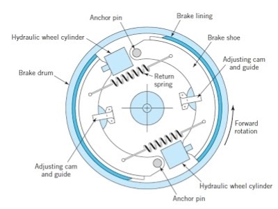
Fig. Internal Expanding shoe brake
Band Brake
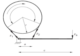
One of the simplest types of braking device is the band brake. This consists of a flexible metal band lined with a frictional material wrapped partly around a drum. The brake is actuated by pulling the band against the drum as illustrated in figure.
Disk Brakes
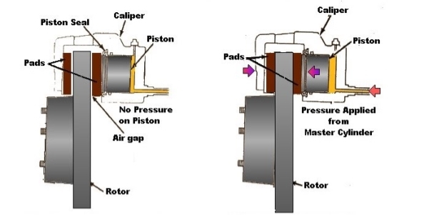
Disc brakes are familiar and common from in automotive applications. They are used extensively in cars and bikes. Disk Brakes consist of a cast iron disc, bolted to the wheel hub. This is sandwiched between two pads actuated by pistons supported in a calliper mounted on the stub shaft . When the brake pedal is pressed, hydraulically pressurized fluid is forced into the cylinders pushing the opposing pistons and brake pads into frictional contact with the disc. The advantages of this form of braking are steady braking, easy ventilation, balancing thrust loads and design simplicity. The use of a discrete pad allows the disc to cool as it rotates, enabling heat transfer between the cooler disc and the hot brake pad.
A band brake is a primary or secondary brake, consisting of a band of friction materials that tightens concentrically around a cylindrical piece of equipment either to prevent it from rotating or to slow it.
A band brake consists of a flexible band of leather, one or more ropes, or a steel lined with a friction material, which embraces a part of a circumference of the drum. It is also termed as simple band brake.
In this one end of the band is attached to a fulcrum of the lever while the other end is attached to the lever at the distance b.
When the force P is applied to the lever C, the lever turns about the fulcrum O and tightens the bands and hence the brakes are applied. Band is the wrapped part round a rotating drum.
Construction of band brake:
Brake band is made of a rope or belt band which is lined with a friction material.
Band is wrapped partially around a drum with its free ends to a lever. An external force can be applied to the free ends of this lever for braking.
Due to the external forces, there is a friction between the bands. Due to this friction force, the band is tightening and a tangential force acts on the drum.
This tightness in the band will create the tension in the band, as a result it stops the wheel connected.
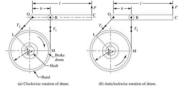
Let T1= Tension in the tight side of the band
T2= Tension in the slack side of the band
Θ= Angle of lap, µ= coefficient of friction between the band and the drum.
r= radius of the drum
t= thickness of the band
re= effective radius of the drum=r+t/2
Key takeaway:
Various geometric configuration of drum brakes are illustrated above Drum Brakes are classified based on the shoe geometry. Shoes are classified as being either short or long. A short shoe is one whose lining dimension in the direction of motion is so small that contact pressure variation is negligible.
Design of band brake:
The operating principle of this type of brake is the following. A flexible band of leather or rope or metallic with friction lining is wound spherical a drum. Frictional torque is generated while anxiety is carried out to the band.
A former software became the locking of tools jewelry in epicyclical gearing. In contemporary-day computerized transmissions this project has been taken over absolutely via way of means of multiple-plate clutches or multiple-plate brakes.
Band brakes may be easy, compact, rugged, and might generate excessive pressure with a mild enter pressure. However, band brakes are at risk of grabbing or chatter and lack of brake pressure while hot.
These troubles are inherent with the layout and for that reason restriction wherein band brakes are a very good solution. In the easy band brake a pressure is carried out thru a lever to a band wrapped a part of the manner round a drum.
This produces tensions with inside the band and the variations among those extended via way of means of the drum radius offers the braking torque.
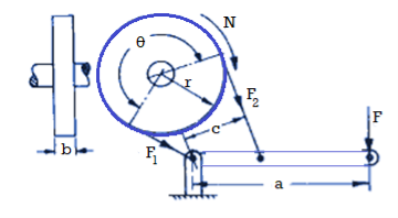
Power P = 2πNT
Torque T = r (F1 – F2)
F1 = brp; F2 = 
Where,
T = braking torque,
P = braking power,
F = applied force,
N = speed of rotation,
a = lever arm,
r = drum radius,
c = distance from belt attachment to fulcrum
External and internal expanding shoe brakes:
External expanding shoe brakes:
- This sort of braking device is often utilized in vehicles as hand brake. In this device the outer layer of the brake drum has a brake lining that's touch with the brake band. The brake band is operated via way of means of brake lever and the linkages to prevent the rotating brake drum.
- By pulling the hand brake lever, the brake band is pressured to press the brake drum tightly. Hence the rotation of brake drum is stopped and the car is stopped. When the hand lever is released, the brake band is loosened and the pressure performing at the brake drum is released.
- External contracting brakes are every so often used for parking brakes on motor vehicles, for cranes, and for controlling the speed of auxiliary equipment power shafts. In operation, the brake band (or shoe) of an outside contracting brake is tightened across the rotating drum via way of means of transferring the brake lever.
- The brake band is product of relatively thin, bendy steel, formed to match the drum, with a frictional lining riveted to the internal surface. This bendy band cannot withstand the excessive stress required to provide the friction had to prevent a closely loaded or fast-transferring car, however it really works nicely as a parking brake or keep brake.
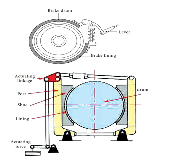
Fig: External expanding brake shoe
Internal Expanding shoe brake:
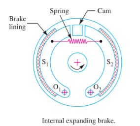
- An internal expanding brake consists of two shoes S1 and S2. The outer surface of the shoes are covered with a few friction material (typically with Frodo) to growth the coefficient of friction and to save you carrying away of the metal.
- Each shoe is pivoted at one cease approximately a set fulcrum O1and O2 and made to touch a cam at the alternative cease.
- When the cam rotates, the footwear are driven outwards in opposition to the rim of the drum. The friction among the footwear and the drum produces the braking torque and therefore reduces the rate of the drum.
- The footwear are usually held in off function via way of means of a spring. The drum encloses the whole mechanism to preserve out dirt and moisture. This sort of brake is usually utilized in motor automobiles and mild trucks.
- In this braking machine the brake footwear are installed inner of brake drum and the decrease ends of brake footwear are related with assist of anchor pins and brake service plate. Based in this the motion of brake shoe is positioned. In among the higher ends of brake footwear one brake cam is installed. Brake pedal is positioned on the proper aspect nook of the driver’s leg.
- When the brake pedal is pressed, a protracted rod that's related with the brake cams with inside the 4 brake service plate concurrently are increased with inside the brake drum which reasons friction that forestalls the rotating wheel. When the brake pedal is released, the brake cam is added to its authentic function.
- The brake footwear also are added to their authentic positions on the equal time without touching the brake drum because of the spring’s compressive force. Hence the wheels at the brake drum rotate without delay without any friction.
Key Takeaways:
- Band brakes may be easy, compact, rugged, and might generate excessive pressure with a mild enter pressure
- In the easy band brake a pressure is carried out thru a lever to a band wrapped a part of the manner round a drum
- When the hand lever is released, the brake band is loosened and the pressure performing at the brake drum is released.
- The brake band is product of relatively thin, bendy steel, formed to match the drum, with a frictional lining riveted to the internal surface.
- Each shoe is pivoted at one cease approximately a set fulcrum O1and O2 and made to touch a cam at the alternative cease.
- When the brake pedal is released, the brake cam is added to its authentic function.
References:
1. Shigley J., Mischke C., Budynas R. And Nisbett K., Mechanical Engineering Design, 8thed., Tata McGraw Hill,2010.
2. Jindal U.C., Machine Design: Design of Transmission System, Dorling Kindersley,2010.
3. Maitra G. And Prasad L., Handbook of Mechanical Design, 2nd ed., Tata McGraw Hill,2001.