Unit - 2
Mechanical Machining Process
- The term ultrasonic is used to describe a vibratory wave of the frequency above that of the upper-frequency limit of the human ear, i.e. generally above 16 kHz. The device for converting any type of energy into ultrasonic waves is the ultrasonic transducer.
- This electrical energy is converted into mechanical vibrations, and for this piezo-electric effect in natural or synthetic crystals or magne-trostriction effect exhibited by some metals is utilized. Magne-trostriction’ means a change in the dimension occurring in ferromagnetic materials subject to an alternating magnetic field.

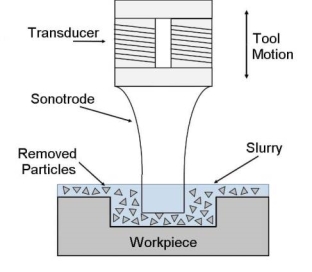
- In ultrasonic machining, a tool vibrating longitudinally at 20 kHz to 30 kHz with an amplitude between 0.01 mm to 0.06 mm is pressed on to the work surface with a light force. As the tool vibrates with a specific frequency, an abrasive slurry, usually a mixture of abrasive grains and water of definite proportion (20% – 30%), is made to flow under pressure through the tool-workpiece interface.
- The impact force arising out of the vibration of the tool end and the flow of slurry through the work-tool interface actually causes thousands of microscopic grains to remove the work material by abrasion. The tool has the same shape as the cavity to be machined.
- The method is employed to machine hard and brittle materials which are either electrically conducting or non-conducting. Analysis of the mechanism of material removal by USM process indicates that it may sometimes be known as Ultrasonic Grinding (USG)
Working Principle of Ultrasonic Machining
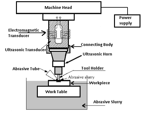
- The figure shows the Ultrasonic machining operation. The electronic oscillator and amplifier, also known as the generator, converts the available electrical energy of low frequency to high-frequency power of the order of 20 kHz which is supplied to the transducer.

- The transducer operates by magnetron striction. The high-frequency power supply activates the stack of the magnetostrictive material which produces longitudinal vibratory motion of the tool. The amplitude of this vibration is inadequate for cutting purposes. This is, therefore, transmitted to the penetrating tool through a mechanical focusing device which provides an intense vibration of the desired amplitude at the tool end.
- The mechanical focusing device is sometimes known as a velocity transformer. This is a tapered shank or known as ‘horn’. It’s upper end being clamped or brazed to the lower face of the magnetostrictive material. Its lower end is provided with means for securing the tool.
- All these parts, including the tool made of low-carbon or stainless steel to the shape of the desired cavity, act as one elastic body transmits the vibrations to the tip of the tool.
The Commonly Used Abrasives Are
- Aluminum oxide (alumina), boron carbide, silicon carbide, and diamond dust. Boron is an expensive abrasive material and it is best suited in the cutting of tungsten carbide, tool steel and gems. Silicon finds its most application for cutting glass and ceramics, alumina is found as the best.
- The abrasive slurry is spread to the work-tool interface by pumping. A refrigerated cooling system is adopted to cool the abrasive slurry to a temperature of 5 to 6 °C. A good method is to keep the slurry in a bath in the cutting zone.
- The size of the abrasive varies between 200 grit and 2000 grit. Coarse grades are good for roughing, whereas finer grades, say 1000 grit, are employed for finishing. Fresh abrasives cuts good and the slurry, therefore, be replaced periodically whenever necessary.
Accuracy
- The maximum speed of penetration in soft and brittle materials such as soft ceramics are of the order of 20 mm min, but for hard and tough materials, the penetration rate is lower. Dimensional accuracy up to t0.005 mm is possible and surface finishes down to a Ra value of 0.1-0.125 micron are often obtained.
- A minimum corner radius of 0.10 mm is possible to finish machining. The range of sizes of USM machines varies from a light portable type having an input of about 20 W to heavy machines taking an input up to 2 kW.
Limitations of the Process
- The main limitation of the process is its relatively low metal cutting rates. The maximum metal removal rate is 3 mm®/s and the power consumption is high. The depth of cylindrical holes is presently limited to 2.5 times the diameter of the tool.
- Wear of the tool increases the angle of the hole, while sharp corners become rounded. This implies that tool replacement is essential in the production of accurate blind holes. Also, the process is limited, in its present form to the machine on surfaces of comparatively small size.
Recent Development
- Recently a new development in ultrasonic machining has taken place in which a tool impregnated with diamond dust is used and no slurry is used. The tool has to be oscillated at ultrasonic frequencies as well as rotated. If it is not possible to rotate the tool then the workpiece may be rotated.
- This innovation has sorted some of the drawbacks of the conventional process in drilling deep holes. For instance, the hole dimensions are often kept within +0.125 mm. Holes of 75 mm depth have been drilled successfully in ceramics without any fall in the rate of machining as is experienced in the conventional process.
Application of Ultrasonic Machining
The simplicity of the process makes it economical for a wide range of applications such as:
- Introducing round holes and holes of any shape for which a tool are often made. The ranges of obtainable shapes are often increased by moving the workpiece during cutting.
- In machining operations like drilling, grinding, profiling and milling operations on all materials both conducting and non-conducting.
- Machining glass, ceramic, tungsten and other hard carbide, gemstones such as synthetic ruby.
- In cutting threads, typically in components made of hard metals and alloys by approximately rotating and translating either the workpiece or the tool.
- In fabricating tungsten carbide and diamond wire drawing dies and dies for forging and extrusion processes.
- Enabling a dentist to drill a hole of any shape or size on teeth without creating any pain.
Advantages and Disadvantages of Ultrasonic Machining
Advantages
- Extremely hard and brittle materials are often easily machined.
- Highly accurate profiles and good surface finish are often easily obtained.
- The machined workpiece is free of stresses.
- The metal removal rate is low.
- Because of practically no heat generation in the process, the physical properties of the work material remain unchanged.
- The operation is noiseless.
- Operation of the equipment is quite safe.
Disadvantages
- The metal removal rate is low.
- The initial equipment cost is higher than the conventional machine tools.
- This process does not suit heavy metal removal
- The cost of tooling is also high.
- Difficulties are encountered in machining softer materials
- Power consumption is quite high.
- The size of the cavity that are often machined is limited.
References:
1. P.C. Pandey and H.S. Shah, Modern Machining Processes, Tata Mcgraw-Hill Publishing Co. Ltd, New Delhi, 1980.
2. A. Ghosh and A.K. Mallik, Manufacturing Science, 2nd edition, Affiliated East West Press, New Delhi.
3. G.F. Benedict, Nontraditional Manufacturing Processes, Marcel Dekker Inc., New York (ISBN 0-8247-7352-7), 1987.
4. V.K. Jain, Advanced Machining Processes, Allied Publishers, 2009.
5. J. A. Mc Geough, Micromachining of Engineering Materials, Taylor & Francis, 2001.