Unit- 2
Thermodynamic Cycles
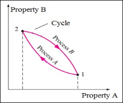 Any process (which the system undergoes) having the initial and final states identical is called as cycle. When any system undergoes a cycle, then it returns to its initial state at the end of the process. That is, for a cycle the initial and final states are same.
Figure 1: Thermodynamic Cycle
2.2.1. OTTO CYCLE:
Otto cycle is a thermodynamic cycle upon which a spark ignition engine works. Spark Ignition (or SI) engine uses petrol (or Gasoline) as fuel. Otto cycle was invented by Nicolas Otto in 1876.
Spark ignition engine is a type of internal combustion engines.
Below are P-V and T-S Diagrams of the Otto Cycle.
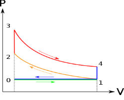
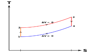
Figure 2: p-v and t-s diagram of otto cycle
Otto Cycle is comprised of four processes (apart from the intake and exhaust process)
Process 1-2: This process comes after intake process. In case of SI engines, intake is a mixture of gasoline and air, also known as charge. In this process charge is compressed in isentropic manner. Temperature raised from T1 to T2 and volume decrease from V1 to V2.
Process 2-3: In this process the fuel gets blasted with the help of external spark (that is why the engine is known as spark ignition engine). This process is a constant volume heat addition process. Temperature raised from T2 to T3
.
Q2-3= CV(T3-T2)
Process 3-4: After the combustion process, the exhaust gases expend. This process is an isentropic expansion process. No heat is interchanged. The temperature fall from T3 to T4 and volume increase from V3 to V4.
Process 4-1: After the expansion process, exhaust valve opens. This results into sudden drop of pressure inside engine cylinder. This process is a constant volume heat rejection process.
Q4-1= CV(T4-T1)
Process 0-1 is the intake process and process 1-0 is the exhaust process.
Efficiency η = 1 – 1 / (r)y-1
2.2.2. DIESEL CYCLE
Diesel cycle is a gas power cycle invented by Rudolph Diesel in the year 1897. It is widely used in diesel engines.
Diesel cycle is similar to Otto cycle except in the fact that it has one constant pressure process instead of a constant volume process (in Otto cycle).
Diesel cycle can be understood well if you refer its p-V and T-s diagrams.
P-V and T-s Diagrams of Diesel Cycle:

|
|
Figure 3: Diesel Cycles
Processes in Diesel Cycle:
Diesel cycle has four processes. They are:
Process 1-2: Isentropic Compression
In this process, the piston moves from Bottom Dead Centre (BDC) to Top Dead Centre (TDC) position. Air is compressed is entropically inside the cylinder. Pressure of air increases from p1 to p2, temperature increases from T1 to T2, and volume decreases from V1 to V2. Entropy remains constant (i.e., s1 = s2). Work is done on the system in this process (denoted by Win in the diagrams above).
Process 2-3: Constant Pressure Heat Addition
In this process, heat is added at constant pressure from an external heat source. Volume increases from V2 to V3, temperature increases from T2 to T3 and entropy increases from s2 to s3.
Heat added in process 2-3 is given by
Qin = mCP(T3 − T2) kJ ………… (i)
Where,
m→ Mass of air in kg
Cp → Specific heat at constant pressure in kJ/kg K
T2 → Temperature at point 2 in K
T3 → Temperature at point 3 in K
Process 3-4: Isentropic Expansion
Here the compressed and heated air is expanded isentropic ally inside the cylinder. The piston is forced from TDC to BDC in the cylinder. Pressure of air decreases from p3 to p4, temperature decreases from T3 to T4, and volume increases from V3 to V4. Entropy remains constant (i.e., s3 = s4). Work is done by the system in this process (denoted by Wout in the p-V and T-s diagrams above).
Process 4-1: Constant Volume Heat Rejection
In this process, heat is rejected at constant volume (V4 = V1). Pressure decreases from P4 to P1, temperature decreases from T4 to T1 and entropy decreases from s4 to s1.
Heat rejected in process 4-1 is given by
Qout = mCv(T4 − T1) kJ ………… (ii)
Where,
m→ Mass of air in kg
Cv → Specific heat at constant volume in kJ/kgK
T2 → Temperature at point 2 in K
T3 → Temperature at point 3 in K
The combustion process in a spark ignition engine does not occur exactly at constant volume, nor does the combustion process in an actual compression ignition engine occur exactly at constant pressure, therefore another idealized cycle known as Dual cycle has been developed that more closely approximate the actual spark-ignition and compression-ignition engines. The p-v and T-s diagrams of Dual cycle are shown in Fig. 45.1. In this cycle, part of heat addition occurs at constant volume while the rest is at constant pressure. The dual cycle is also called mixed or limited pressure cycle.
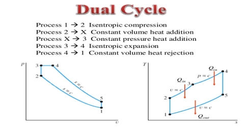
Figure 4: dual cycle
In a dual cycle, the system executing the cycle undergoes a series of five processes: two isentropic (reversible adiabatic) processes alternated with two isochoric process and one isobaric process:
Dual cycle – PV Diagram
Isentropic compression (compression stroke) – The gas is compressed adiabatically from state 1 to state 2, as the piston moves from intake valve closing point (1) to top dead centre. The surroundings do work on the gas, increasing its internal energy (temperature) and compressing it. On the other hand the entropy remains unchanged. The changes in volumes and its ratio (V1 / V2) are known as the compression ratio. The compression ratio is smaller than the expansion ratio.
Isochoric compression (ignition phase) – In this phase (between state 2 and state 3) there is a constant-volume (the piston is at rest) heat transfer to the air from an external source while the piston is at rest at top dead center. This process is similar to the isochoric process in the Otto cycle. It is intended to represent the ignition of the fuel–air mixture injected into the chamber and the subsequent rapid burning. The pressure rises and the ratio (P3 / P2) is known as the “explosion ratio”.
Isobaric expansion (power stroke) – In this phase (between state 3 and state 4) there is a constant-pressure (idealized model) heat transfer to the air from an external source (combustion of the fuel) while the piston is moving toward the V4. During the constant pressure process, energy enters the system as heat Qadd, and a part of work is done by moving piston.
Isentropic expansion (power stroke) – The gas expands adiabatically from state 4 to state 5, as the piston moves from V3 to bottom dead center. The gas does work on the surroundings (piston) and loses an amount of internal energy equal to the work that leaves the system. Again the entropy remains unchanged.
Isochoric decompression (exhaust stroke) – In this phase the cycle completes by a constant-volume process in which heat is rejected from the air while the piston is at bottom dead center. The working gas pressure drops instantaneously from point 5 to point 1. The exhaust valve opens at point 5. The exhaust stroke is directly after this decompression. As the piston moves from bottom dead center (point 1) to top dead center (point 0) with the exhaust valve opened, the gaseous mixture is vented to the atmosphere and the process starts anew.
During the Dual cycle, work is done on the gas by the piston between states 1 and 2 (isentropic compression). Work is done by the gas on the piston between stages 2 and 3 (isobaric heat addition) and between stages 2 and 3 (isentropic expansion). The difference between the work done by the gas and the work done on the gas is the network produced by the cycle and it corresponds to the area enclosed by the cycle curve. The work produced by the cycle times the rate of the cycle (cycles per second) is equal to the power produced by the Diesel engine.
Key Takeaways:
There are three major types of Gas Power Cycles:
It is theoretical cycle for gas turbines. It is also known as constant pressure cycle for a perfect gas. The basic component of Brayton Cycle is as shown in given figure-
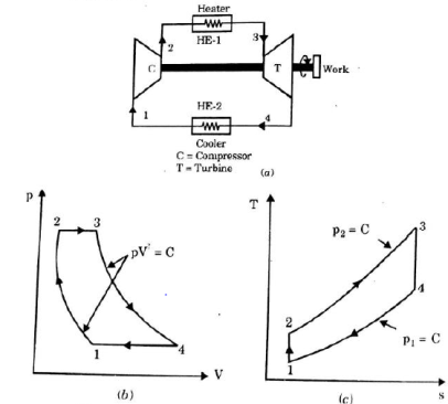
Figure 5: Brayton Cycle
The components are compressor, heat exchanger, turbine and cooler.
There occur two isentropic processes and two constant pressure processes. Compression and expansion of working fluid is done by isentropic process while addition and rejection of heat is done at constant pressure. In above figure, we can see the p-v and T-s diagram for the cycle.
Process 1-2: Air is being compressed is entropically by compressor between the pressure range p1 to p2.
Process 2-3: It is constant pressure heat pressure heat addition process. In this process temperature increases from T2 to T3 at constant pressure.
Process 3-4: The air is expanded is entropically pressure p2 to p1 and the temperature drops from T3 to T4.
Process 4-1: It is constant pressure heat rejection process as temperature reduces from T4 to T1.
Now, Work done per cycle=Heat added/cycle-Heat rejected/cycle
Heat addition in process 2-3=mCp(T3-T2)
Heat rejected in process 4-1= mCp(T4-T1)
Work done per cycle=mCp(T3-T2)-MCp(T4-T1)


From process 1-2


Similarly from process 3-4

Putting the values  and
and  in equation


The above equation shows that the efficiency of the ideal Brayton cycle increases with the pressure ratio.
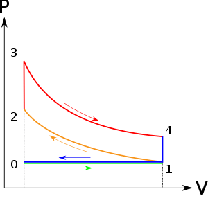
Figure 6: Effect of pressure ratio on the efficiency of Brayton Cycle
Key Takeaways:
It is theoretical cycle for gas turbines. It is also known as constant pressure cycle for a perfect gas.
2.4.1. Effect of Reheating of Steam:
In the warm cycle, the extension of steam from the initial state 1 to the condenser pressure is completed in at least two or more stages relying on the quantity of reheat utilized.
Cycle efficiency: improves with reheat, anyway the cycle productivity in a solitary warm plant is affected by pressure at which steam is warmed. The efficiency increment as the reheat pressing factor is brought down and arrives at a top at a pressing factor proportion somewhere in the range of 0.20 and 0.25.
Warming steam likewise increment the organization yield of turbine
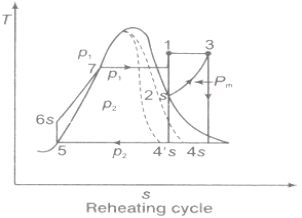
Fig 7: Reheating Cycle

Reheating steam also increase the network output of turbine.
Advantages of Re‑heating:
1) Due to reheating, network done increments.
2) Heat supply increments.
3) Thermal effectiveness tangle increment or diminishing relying on the mean temperature of warmth expansion.
4) Due to reheating, the turbine exit dryness fraction increases so moisture decreases ‑ so blade erosion becomes minimum ‑ so life of the turbine will be increased.
2.4.2. Regeneration:
(i).The mean temperature of heat addition (thus proficiency) can likewise be expanded by reducing the amount of heat added at low temperatures in the economizer part of steam generator.
(ii) In the recovery cycle energy is exchanged inside between the extending fluid in the turbine and the compressed liquid before heat expansion.
(iii).Ideal regenerative cycle does not influence work output from turbine, it is more productive with high steam rate.
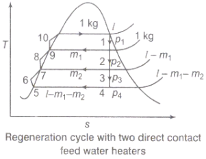
Fig 8: Regeneration Cycle
Efficiency of Steam Power Plant: Overall efficiency of the steam per plant is given by


Key Takeaways:
2.5.1. Vapour Power Cycle
Generally water is used a working fluid in vapour power cycle as it is discovered to be superior to some other liquid, yet it is a long way from being the ideal one. The binary cycle is an attempt to overcome a portion of the shortcomings of water and to move toward the ideal working liquid by utilizing two liquids. The main attractive qualities of the working liquid appropriate for vapour cycles are:
a. High basic temperature and a protected most extreme pressing factor.
b. Low-triple point temperature
c. Condenser pressure isn't excessively low.
d. High enthalpy of vaporization
e. High thermal conductivity
f. It should be promptly accessible, modest, inert and non-harmful.
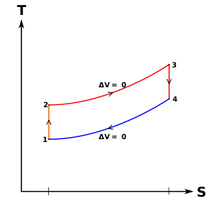
Figure 9: Mercury-steam vapour power cycle
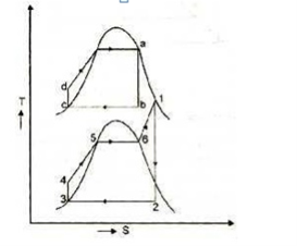
Figure 10: Vapor power Cycle
Therefore, it can be concluded that no single working fluids may have desirable requirements of working fluid. Different working fluids may have different attractive feature in them, but not all. In such cases two vapour cycles operating on two different working fluids are put together, one is high temperature region and the other in low temperature region and the arrangement is called binary vapour cycle.
The layout of mercury-steam vapour power cycle is shown in figure. Along with the depiction of T-S diagram figure. Since mercury having high critical temperature (898oC) and low critical pressure (180 bar) which makes a suitable working fluid will act as high temperature cycle (toppling cycle) and steam cycle will act as low temperature cycle.
Here mercury vapour are generated in mercury boiler and sent for expansion in mercury turbine and expanded fluid leaves turbine to condenser. In condenser, the water is used for extracting heat from the mercury so as to condensate it. The amount water entering mercury condenser. The mercury condenser also act as steam boiler for super heating of heat liberated during condensation of mercury is too large to evaporate the water entering of seam an auxiliary boiler may be employed or superheating may be realized in the mercury boiler itself. From the cycle,
Since pump works are very small, it may be neglected. Work from Mercury Turbine, WHg =mg (ha -hb)
Work from Steam Turbine, Wsteam = msteam (h1 -h2)
Pump work, Wpump = mHg (hd -hc)+msteam (h4 -h3)
Key Takeaways:
Heat supplied to the cycle, Qin =mHg (ha -hd)+msteam [(h1 -h6)+(h5 -h4)]
Heat rejected= Qout =mstream(h2-h3)
Efficiency of binary vapour cycle η =W net /Qin
Net work done =W net= Heat supplied =Qin =mHg (ha -hd) +msteam [(h1 -h6)+(h5 -h4 )]
2.5.2. Combined power cycle:
The proceeded with mission for higher warm efficiencies has brought about rather inventive alterations to traditional force plants. The parallel fume cycle examined later is one such alteration. A more well-known alteration includes a gas power cycle besting a fume power cycle, which is known as the joined gas–fume cycle, or simply the consolidated cycle. The joined pattern of most noteworthy interest is the gas-turbine (Brayton) cycle beating a steam turbine
Rankine cycle which has a higher warm effectiveness than both of the cycles executed exclusively Gas-turbine cycles normally work at impressively higher temperatures than steam cycles. The greatest liquid temperature at the turbine bay is about 620°C (1150°F) for current steam power plants, yet over 1425°C (2600°F) for gas-turbine power plants. It is over 1500°C at the burner exit of turbojet motors. The utilization of higher temperatures in gas turbines is made conceivable by on-going improvements in cooling the turbine cutting edges and covering the edges with high-temperature-safe materials, for example, earthenware production. In view of the higher normal temperature at which warmth is provided, gas-turbine cycles have a more prominent potential for higher warm efficiencies. Notwithstanding, the gas-turbine cycles have one inalienable hindrance: The gas leaves the gas turbine at high temperatures (as a rule above 500°C) which deletes any possible increases in the warm productivity. The circumstance can be improved to some degree by utilizing recovery, yet the improvement is restricted. It bodes well to exploit the entirely attractive qualities of the gas-turbine cycle at high temperatures and to utilize the high temperature fumes gases as the fuel hotspot for the lining cycle, for example, a steam power cycle. The outcome is a joined gas–steam cycle, as appeared
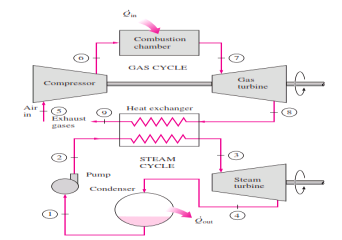
Figure 11: Combined gas–steam power plant
In this cycle, energy is recovered from the exhaust gases by transferring it to the steam in a heat exchanger that serves as the boiler. In general, more than one gas turbine is needed to supply sufficient heat to the steam. Also, the steam cycle may involve regeneration as well as reheating. Energy for the reheating process can be supplied by burning some additional fuel in the oxygen-rich exhaust gases. Recent developments in gas-turbine technology have made the combined gas–steam cycle economically very attractive. The combined cycle increases the efficiency without increasing the initial cost greatly. Consequently, many new power plants operate on combined cycles, and many more existing steam- or gas-turbine plants are being converted to combined-cycle power plants. Thermal efficiencies well over 40 percent are reported as a result of conversion.
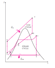
Figure 12: Combined Gas Cycle
Kay Takeaways:
In this cycle, energy is recovered from the exhaust gases by transferring it to the steam in a heat exchanger that serves as the boiler. In general, more than one gas turbine is needed to supply sufficient heat to the steam. Also, the steam cycle may involve regeneration as well as reheating.
2.6 Vapor compression refrigeration cycles and comparison with carnot cycle:
Vapour-compression refrigeration or vapor-compression refrigeration system (VCRS), in which the refrigerant undergoes phase changes, is one of the many refrigeration cycles and is the most widely used method for air-conditioning of buildings and automobiles.
Vapor-compression cycle refrigeration is a process that uses the physics of phase change heat transfer and the unique properties of a refrigerant to transfer heat from a relatively cold source to a hot medium. Simply stated, refrigeration systems efficiently move heat from a cold source to a hot heat sink (normally air). The components in the basic refrigeration system are the compressor, condenser, expansion valve, and evaporator.
The heart of the system is the compressor. The compressor takes in a low temperature, low pressure refrigerant vapor, and compresses it into a high temperature, high pressure vapor. This high temperature/pressure vapor then enters the condenser where heat is removed to either air or water. As the heat is removed, the energy stored in the high pressure gas is released and the refrigerant gives up its latent heat as it reverts to a hot liquid.
This hot, high temperature liquid then exits the condenser and enters the expansion valve, where it undergoes a pressure drop causing some of the hot gas to vaporize. This lowers the temperature of the refrigerant stream. The refrigerant at the exit of the expansion valve is a low temperature two-phase fluid.
This two-phase fluid enters the evaporator where it is exposed to the heat source. The heat from the source boils off the refrigerant through phase change heat transfer, and the low temperature, low pressure gas enters the compressor, completing the cycle.
It is useful to understand the refrigerant cycle in the quadrant shown in Figure 13. The high pressure, high temperature upper half allows the refrigerant to become significantly hotter than ambient air, forcing heat transfer into a habitually hot environment.
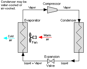
Figure 13: Vapor Compression System
The low temperature, low pressure half of the cycle allows the refrigerant to absorb heat from a source that is not as hot as the environment. The compressor does the work to raise the pressure, and the expansion valve assures that adequate pressure is retained in the condenser for heat transfer.
The vapor compression cycle can be used to cool air, liquid, or cold plates. All that is required to accomplish this is to modify the evaporator to accommodate the systems that are being cooled. To create an air cooling system, the evaporator acts as a refrigerant to an air heat exchanger. The air cooling system is used in buildings, automobiles, and in electronics enclosures where air cooled rack-mounted equipment is being cooled.
To cool liquid, the evaporator again acts as a refrigerant, this time to a liquid heat exchanger, with the pumped liquid being cooled by the evaporating refrigerant. The liquid cooled system is used for systems such as lasers, electronics, and medical devices that are designed for liquid cooling.
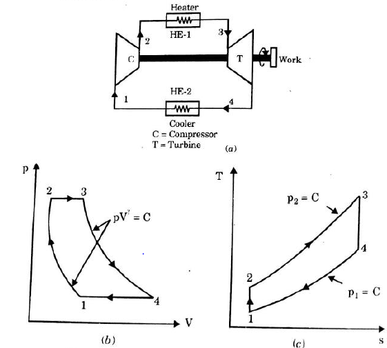
Figure 14: Vapor Compression Cycle
The thermodynamics of the vapor compression cycle can be analyzed on a temperature versus entropy diagram as depicted in Figure 2. At point 1 in the diagram, the circulating refrigerant enters the compressor as a saturated vapor. From point 1 to point 2, the vapor is entropically compressed (compressed at constant entropy) and exits the compressor as a superheated vapor. Superheat is the amount of heat added above the boiling point.
From point 2 to point 3, the vapor travels through part of the condenser which removes the superheat by cooling the vapor. Between point 3 and point 4, the vapor travels through the remainder of the condenser and is condensed into a saturated liquid. The condensation process occurs at essentially constant pressure.
Between points 4 and 5, the saturated liquid refrigerant passes through the expansion valve and undergoes an abrupt decrease of pressure. That process results in the adiabatic flash evaporation and auto-refrigeration of a portion of the liquid (typically, less than half of the liquid flashes). The adiabatic flash evaporation process is isenthalpic (occurs at constant enthalpy).
Between points 5 and 1, the cold and partially vaporized refrigerant travels through the coil or tubes in the evaporator where it is totally vaporized by the warm air (from the space being refrigerated) that a fan circulates across the coil or tubes in the evaporator. The evaporator operates at essentially constant pressure and boils off all available liquid there after adding 4–8 kelvins of superheat to the refrigerant in order to make sure the liquid has evaporated completely. This is a safeguard for the compressor, as it cannot pump liquid. The resulting refrigerant vapor returns to the compressor inlet at point 1 to complete the thermodynamic cycle.
The above discussion is based on the ideal vapor-compression refrigeration cycle which does not take into account real world items like frictional pressure drop in the system, slight internal irreversibility during the compression of the refrigerant vapor, or non-ideal gas behaviour.
Comparison between Vapor compression refrigeration and carnot cycle:
Key Takeaways:
The vapor compression cycle can be used to cool air, liquid, or cold plates. All that is required to accomplish this is to modify the evaporator to accommodate the systems that are being cooled. To create an air-cooling system, the evaporator acts as a refrigerant to an air heat exchanger.
A refrigerant is a working fluid used in the refrigeration cycle of air conditioning systems and heat pumps where in most cases they undergo a repeated phase transition from a liquid to a gas and back again.
The most common refrigerant include Chlorofluorocarbons (CFCs), Hydrochlorofluorocarbons (HCFCs), Hydrofluorocarbons (HFCs), and Natural Refrigerants. Freons or halocarbons are synthetically produced. The classification also depends on their chemical elements chlorine (Cl), hydrogen (H), carbon (C), and Florine (F)
Physical Properties of Refrigerants
Key Takeaways:
The vapour compression cycle can be used to cool air, liquid, or cold plates. All that is required to accomplish this is to modify the evaporator to accommodate the systems that are being cooled. To create an air cooling system, the evaporator acts as a refrigerant to an air heat exchanger
References:
1) Engineering thermodynamics P.K nag
2) I.C engineering by ML Mathur