Basic Rankine Cycle:
The Rankine cycle is a cycle that converts heat into work. The heat is supplied externally to a William John Macquorn Rankine closed loop, which usually uses water. This cycle generates about 90% of all electric power used throughout the world.
In a real Rankine cycle, the compression by the pump and the expansion in the turbine are not isentropic. In other words, these processes are irreversible and entropy is increased during the two processes. This somewhat increases the power required by the pump and decreases the power generated by the turbine.
This cycle is the fundamental operating cycle for all the power plants where an operating fluid is continuously evaporated and condensed.
The Rankine cycle is the major working pattern of all force plants where a working liquid is constantly evaporated and condensed.
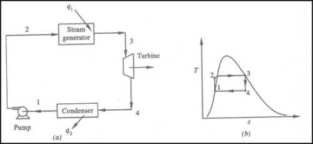
Figure 1: rankine Cycle
•1-2 Isentropic Pressure:
The squeezing element of the condensate is raised in the feed siphon. Considering the low unequivocal volume of fluid, the siphon work is moderately little and regularly excused in thermodynamic estimations.
• 2-3 Isobaric Heat Transfer
High-pressure fluid enters the heater from the feed siphon (1-2) and is warmed to the immersion temperature (2). Further extension of energy causes dissipation of the fluid until it is totally changed over to immersed steam (3)
• 3-4 Isentropic Expansions:
The vapour is extended in the turbine, in this way making work which may be changed over to power. in practice the extension is limited by the temperature of the cooling medium and by the disintegration of the turbine cutting edges by liquid entrainment in the fume stream as the cycle moves further into the two-stage district. Leave fume attributes should be more noteworthy than 90%.
4-1 Isobaric Heat Rejection:
The vapour liquid mixture leaving the turbine (3-4) is condensed at low pressure generally in a surface condenser utilizing cooling water. In very much planned and looked after condensers, the pressing factor of the vapour is well below atmospheric pressing, moving toward the immersion pressing factor of the working liquid at the cooling water temperature.
Energy added in steam generator: q1= h3 – h2
Energy rejected in the condenser, q2 =h4 – h1

Reheating of Steam:
In the warm cycle, the extension of steam from the initial state 1 to the condenser pressure is completed in at least two or more stages relying on the quantity of reheat utilized.
Cycle efficiency: improves with reheat, anyway the cycle productivity in a solitary warm plant is affected by pressure at which steam is warmed. The efficiency increment as the reheat pressing factor is brought down and arrives at a top at a pressing factor proportion somewhere in the range of 0.20 and 0.25.
Warming steam likewise increment the organization yield of turbine
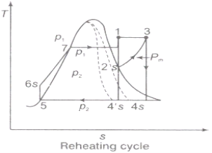
Figure 2: Reheating Cycle

Reheating steam also increase the network output of turbine.
Advantages of Re‑heating:
1) Due to reheating, network done increments.
2) Heat supply increments.
3) Thermal effectiveness tangle increment or diminishing relying on the mean temperature of warmth expansion.
4) Due to reheating, the turbine exit dryness fraction increases so moisture decreases ‑ so blade erosion becomes minimum ‑ so life of the turbine will be increased.
Regeneration:
(i)The mean temperature of heat addition (thus proficiency) can likewise be expanded by reducing the amount of heat added at low temperatures in the economizer part of steam generator.
(ii) In the recovery cycle energy is exchanged inside between the extending fluid in the turbine and the compressed liquid before heat expansion.
(iii)Ideal regenerative cycle does not influence work output from turbine, it is more productive with high steam rate.
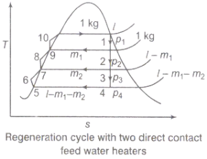
Fig 3: Regeneration Cycle
Efficiency of Steam Power Plant: Overall efficiency of the steam per plant is given by


Combined Cycle Power Generation:
It is a gathering of heat engine that works with a comparative wellspring of heat. The standard of consolidated cycle power generation is that the exhaust of one heat engine is utilized as the source of heat for another heat engine. This process increases the overall efficiency of a heat engine.

Advantages of Regeneration cycle:
Characteristics of Ideal Working Fluid
1) The fluid ought to have high critical temperature and the saturation pressure at the temperature of heat rejection ought to be over the climatic pressing factor.
2) Specific heat of fluid ought to be little.
3) The saturated vapour line of T-s outline near the turbine extension measure.
4) The freezing point of the fluid should be below the room temperature
5) The liquid ought to be synthetically steady, non-poisonous, non-destructive, not exorbitantly viscous and low in expense.
Superheating the steam to a high temperature
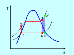
Figure 4: The effect of Superheating the Steam to a Higher Temperature
The impact of superheating the steam to a high temperature on the Rankine cycle proficiency is outlined on a T-s graph on the left. By superheating the stream to a high temperature (from state 3 to state 3'), the normal steam temperature during heat expansion can be increased. The blue zone is the net work expanded due to superheating the steam to a high temperature.
Key Takeaways:
1) Internal irreversibility of Rankine cycle (Genuine cycle) is brought about by fluid frictions throttling and mixing.
2) Externally, irreversibility of the Rankine cycle is caused because of the temperature distinction between the burning gases and the working liquid on a similar side and the temperature contrast between the consolidating working liquid and the condenser cooling water on the sink side.
3) Due to reheating, the turbine exit dryness fraction increases so moisture decreases ‑ so blade erosion becomes minimum ‑ so life of the turbine will be increased.
The strategy for exergy analysis focuses on the quantitative assessment of the exergy misfortunes (irreversibility) related with a framework. Consequently, it is needed to compute the irreversibility in all the parts of the power cycle for the estimation of exergy efficiency. The irreversibility or exergy misfortune in every one of the segments is determined for the predetermined dead state (P0, T0).
Boiler:
The mass flow rate of steam (ms) needed to be created in the boiler to deliver a output of 500MW power can be acquired from the energy balance as given below:
ms = 500×1ooo kW/Wnet kg/s (1)
Using this, the mass of the flue gas (mg) required to obtain the required mass flow rate of steam can be found by the energy balance equation i.e.,
Heat gained by the steam = Heat lost by the flue gas
ms (h1 − h4) = mg (hA − hB)
mg = ms (h1−h4)/(hA−hB) (2)
Exergy or Accessibility at state point 1
E1 = ms (h1 − T0s1) kW (3)
Exergy or Accessibility at state point 4
E4 = ms (h4− T0s4) kW (4)
Irreversibility in the boiler is,
IBOILER = (EA− EB) − (E1− E4) kW (5)
Substituting the E1, E4 from Eq. (3) & (4)
IBOILER = mg (EA− EB) – ms [(h1− h4) − T0 (s1− s4)] kW (6)
Steam Turbine:
The irreversibility in the steam turbine is given by
ITURBINE = T0 ms (s2− s1) kW (7)
Condenser:
Mass flow rate of cooling water circulated to condense ms,
Kg /s of steam is obtained from the energy balance is
mcwcpw(Twi − Two) = ms(h2− h3)
mcw = ms (h2−h3)/cpw(Twi−Two) (8)
Irreversibility in the condenser,
ICONDENSER = T0[ms(s2− s3) − (mcwcpwln (Two/Twi)]kW (9)
Exhaust:
Irreversibility of the exhaust,
IEXHAUST = EB (10)
Pump:
Irreversibility rate in the boiler feed pump,
IPUMP = msT0(s2− s1)kW (11)
Total Irreversibility:
Total Irreversibility is,
ITOTAL = [IBOILER + ITURBINE + ICONDENSER + IEXHAUST + IPUMP]kW (12)
Fractional Exergy loss:
The meaning of the fractional exergy loss of the segment is the ratio of irreversibility of the individual part to the total irreversibility of the cycle. Its worth is assessed for all the parts of the cycle. It gives the data with respect to the deficiency of valuable energy in all parts for various working factors. The fractional exergy misfortune equations of every segment are as per the following,
Fractional exergy loss in the boiler is IBOILER/ ⅀I × 100 (13)
Fractional exergy loss in the turbine is
ITURBINE/ ⅀I × 100 (14)
Fractional exergy loss in the condenser is,
ICONDENSER / ⅀I × 100 (15)
Fractional exergy loss in the Pump is,
IPUMP/⅀I × 100 (16)
Fractional exergy loss in the exhaust is,
IEXHAUST / ⅀I × 100 (17)
Supercritical Rankine cycle is also the thermodynamic cycle of supercritical water reactors. The supercritical water reactor (SCWR) is a concept of Generation IV reactor, that is operated at supercritical pressure (i.e., greater than 22.1 MPa). The term supercritical in this context refers to the thermodynamic critical point of water (Tcr = 374 °C; Pcr = 22.1 Mpa), and must not be confused with the criticality of the reactor core, that describes changes in the neutron population in the reactor core.
As we discussed the thermal efficiency can be improved “simply” by an increase in the temperature of the steam entering the turbine. But this temperature is restricted by metallurgical limitations imposed by the materials and design of the reactor pressure vessel and primary piping. The reactor vessel and the primary piping must withstand high pressures and great stresses at elevated temperatures. But currently, improved materials and methods of fabrication have permitted significant increases in the maximum pressures, with corresponding increases in thermal efficiency. The thermal power plants are currently designed to operate on the supercritical Rankine cycle (i.e., with steam pressures exceeding the critical pressure of water 22.1 Mpa, and turbine inlet temperatures exceeding 600 °C). Supercritical fossil fuel power plants, that are operated at supercritical pressure, have efficiencies around 43%. Most efficient and also very complex coal-fired power plants that are operated at “ultra-critical” pressures (i.e., around 30 Mpa) and use multiple stage reheat reach about 48% efficiency.
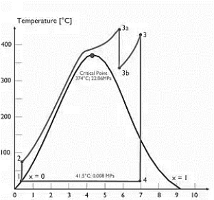
Specific Entropy [kj/kgK]
Figure 5: Supercritical Rankine cycle
Key takeaway:
Most efficient and also very complex coal-fired power plants that are operated at “ultra-critical” pressures (i.e., around 30 Mpa) and use multiple stage reheat reach about 48% efficiency.
Reference
1) Engineering thermodynamics P.K nag
2) I.C engineering by M.L. Mathur