Unit-5
Analysis of steam turbines
A steam turbine is a prime mover in which the potential energy of the steam is transformed into kinetic energy and later in its turn is transformed into the mechanical energy of rotation of the turbine shaft.
Classification:
Most common classification of steam turbine-
(i) Impulse Turbine
(ii) Reaction Turbine
Other classifications are: -
(i) According to the number of pressure stages
(ii) According to the type of steam flow
(iii) According to the number of shafts/cylinders
(iv) According to the method of governing
(v) According to the steam conditions at inlet to turbine
According to the action of steam:
2. According to the type of steam flow:
3. According to the number of shafts:
4. According to the method of governing:
5. According to the steam conditions at inlet to turbine:
Simple impulse principle:
Construction and Working of impulse turbine:
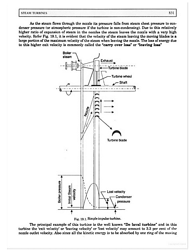
Figure 1: Simple impulse turbine
Velocity diagram for steam turbine:


For the convenience of solving the problem related to the turbine we can make the velocity diagram as shown in fig.2.
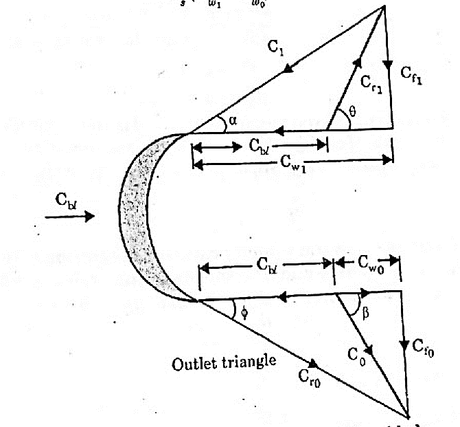
Figure 2: Velocity diagram for moving blade
Tangential force on the wheel = Mass of the steam * acceleration
Mass of steam/seconds * change in velocity

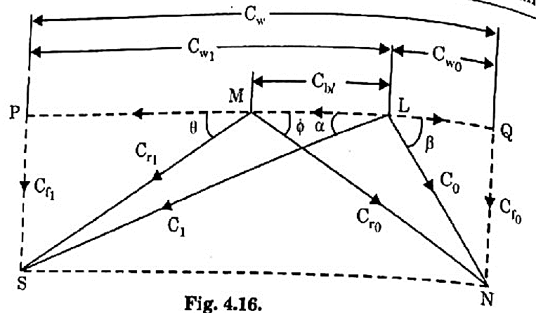
Figure 3: Velocity triangle of moving blade
Work done on blade / second = Force * distance travelled / second
Power on blade second is given by-

Blade or diagram efficiency = 

Reaction turbine
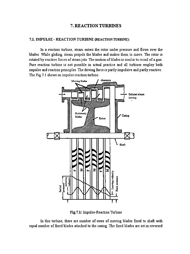
Figure 4: Reaction Turbine
Key Takeaways:
Difference between Impulse turbine and Reaction turbine:
Impulse Turbine | Reaction Turbine |
The steam completely expands in the nozzle and its pressure remains constant during its flow through the blade passages. | The steam expands partially in the nozzle and further expansion takes place in the rotor blades. |
The relative velocity of steam passing over the blade remains constant in the absence of friction. | The relative velocity of steam passing over the blade increases as the steam expands while passing over the blade. |
The steam velocity is very high and therefore the speed of turbine is high. | The steam velocity is not very high and therefore the speed of turbine is low. |
The pressure on both ends of the moving blade is same. | The pressure on both ends of the moving blade is different |
For the same power developed, as pressure drop is more, the number of stages required are less. | For the same power developed, as pressure drop is small, the number of stages required are more. |
Blades are symmetrical | Blades are asymmetrical |
The blade efficiency curve is less flat. | The blade efficiency curve is more - flat |
1)Velocity compounding
2)Pressure compounding, and
3)Pressure-Velocity compounding.
5.2.1. Velocity compounding:
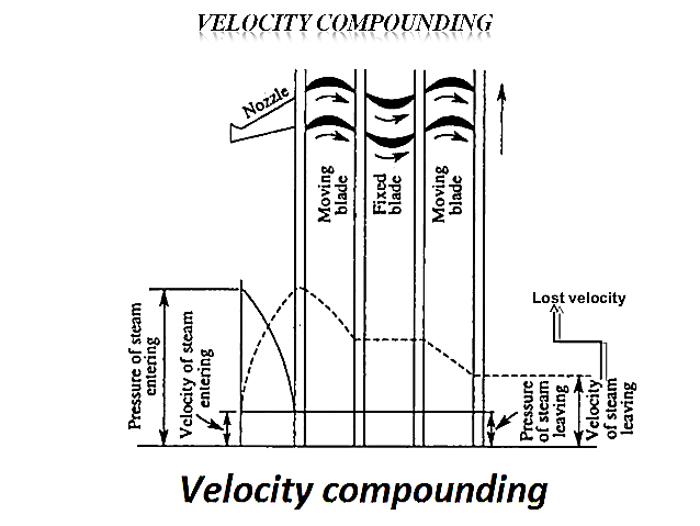
Figure 5: Velocity compounding
5.2.2. Pressure compounding:
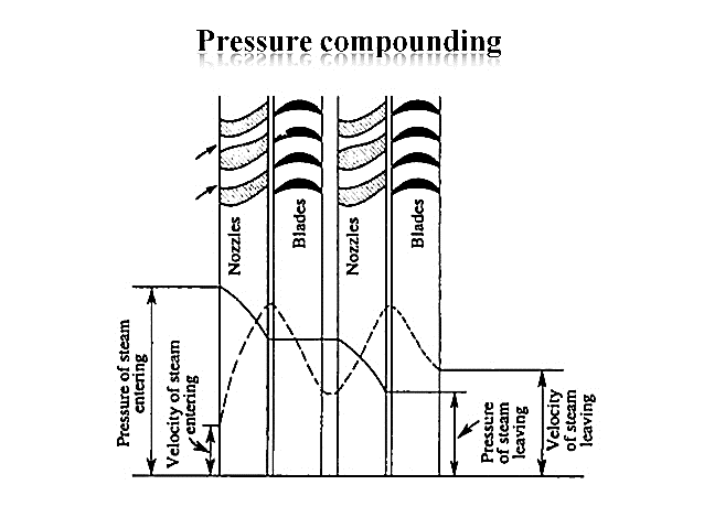
Figure 6: Pressure compounding
5.2.3. Pressure-velocity compounding:
The pressure-velocity compounding is the compounding is the combination of the above two types of compounding. In fact series of velocity-compounded impulse stages is called a pressure velocity compounded turbine. Each stage consists of rings of fixed and moving blades.
Each set of rings of moving blades is separated by a single ring of fixed nozzles. In each stage there is one ring of fixed nozzles and 3-4 rings of moving blades (with fixed blades between them). Each stage acts as a velocity compounded impulse turbine.
The steam coming from the steam generator is passed to the first ring of fixed nozzles, where it gets partially expanded. The pressure partially decreases and the velocity rises correspondingly. It then passes over the 3-4 rings of moving blades (with fixed blades between them) where nearly all of its velocity is absorbed. From the last ring of the stage it exhausts into the next nozzle ring and is again partially expanded.
This has the advantage of allowing a bigger pressure drop in each stage and, consequently, less stages are necessary, resulting in a shorter turbine for a given pressure drop. It may be seen that the pressure is constant during each stage; the turbine is, therefore, an impulse turbine. The method of pressure-velocity compounding is used in the Curtis turbine.
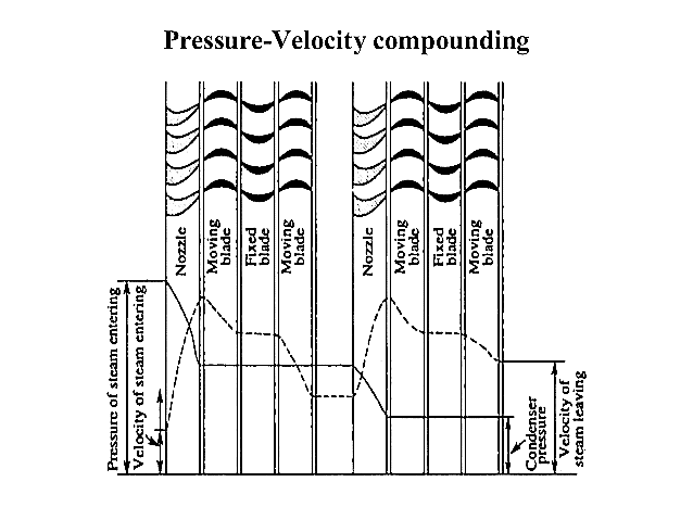
Figure 7: Pressure-velocity compounding
Reference
1) Engineering thermodynamics P.K nag
2) I.C engineering by M.L.Mathur