Unit-4
Heat treatment of Steel
4.1. Heat Treatment of steel:
Heat treatment may be defined as an operation involving the heating of solid metal to definite temperature, followed by cooling at suitable rates in order to obtain certain physical properties which are associated with changes in the nature, form size and distribution of the micro-constituents.
4.1.1. Annealing:
Annealing is a het treatment process that alters the physical and sometimes chemical properties of a material to increase its ductility and reduce its hardness, making it more workable.
Annealing consists of:


4.1.2. Tempering:
The tempering process provides a method for transforming martensite into ferrite and cementite. How much of the martensite is transformed depends on the temperature and time of the tempering process.
Tempering occurs in four stages:
Stage 1:


Stage 2:

Stage 3:

Stage 4:
4.1.3. Normalizing:


4.1.3. Spheroidising:
This is a form of annealing in which cementite is in the granular (globular) form is produced in the structure of steel.
This process causes the agglomeration of all carbides in the steel in the form of small globules or spheroids.
This process is usually applied to high-carbon steels which are difficult to machine.
The process consists of heating the steel slightly above the lower critical point ( ) holding at this temperature, and then cooling slowly to a temperature of
  .
.
The rate of cooling in the furnace is from  per hour.
Key Takeaways:
4.2. Isothermal transformation diagram for Fe-C alloys and microstructure development:
Isothermal transformation diagrams (also known as time-temperature-transformation (TTT) diagrams) are plots of temperature versus time (usually on a logarithmic scale).
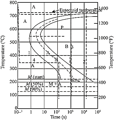
Figure 1.Isothermal Transformation Diagram
Key Takeaways:
4.3. Continuous cooling curves:
In actual practice steel is generally cooled continuously. Continuous cooling transformation (C-C-T) diagrams depict this situation.
The C-C-T curve (dark line) is shifted to the right of the T-T-T(dashed) curve as continuous cooling transformation occurs at lower temperature and longer time compared to isothermal bonding.
Bainite generally doesn’t form in steels during continuous cooling and hence the C-C-C-T curve ceases just below the nose.
The microstructure (fine or coarse) depends on the cooling rate. Higher the cooling rate finer the microstructure is.
The critical cooling rate is the one at which the cooling curve just touches the nose pf the C-C-T curve.
A cooling rate is higher than the critical rate is needed to form martensite.
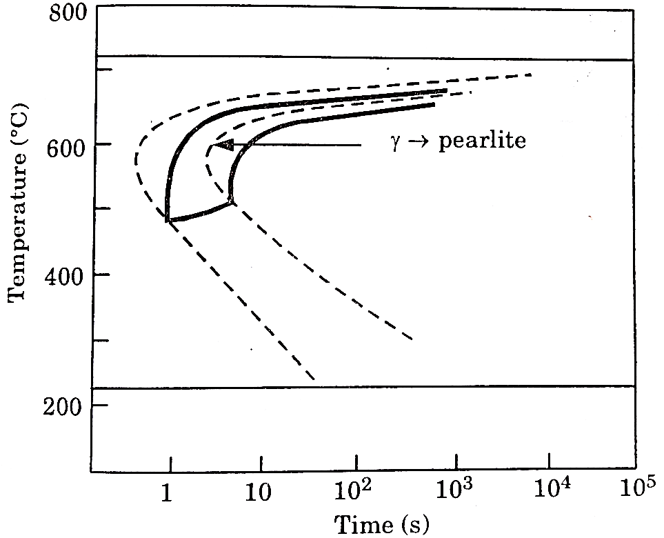
Figure 2: C-C-T Curve
Key Takeaways:
4.4. T-T-T diagram and interpretation of final microstructure and properties:
Temperature-Time -Transformation diagram represents a relation between starting and ending of the formation of different microstructures.
Its shape is name as English alphabet ‘C’ so it is known as C-curve.
The nose of this curve indicates the least time taken for a particular transformation.
The line passes through the nose (or tangent at the nose of C-curve) is known as critical cooling curves and its slope is termed as critical cooling rate.
In this fig. transformation of austenite to pearlite is shown. The left most T- curve shows the starting of transformation of austenite into pearlite.
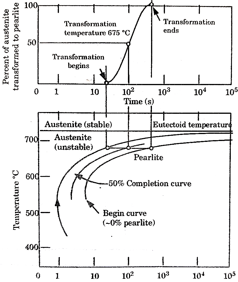
Figure 3: TTT diagram
At the 0% pearlite, 100%austenite is present. Then the dashed curve represents that 50% of austenite transforms into pearlite and the right most C-curve represents (completion curve) 100% pearlite transformation.
These curves are accurate only for the transformations in which the temperature of alloy is held constant throughout the duration of the reactions.
Thus, these plots are also known as isothermal transformational diagrams or T-T-T diagrams.
Depending upon different cooling rate various microstructure can be obtained like pearlite (coarse or fine), bainite, austenite + martensite and martensite.
When cooling rate is slow, we get line pearlite which is done by annealing.
In normalizing the cooling rate is high by which we get bainite structure.
A complete feature of T-T-T diagram to show its different phase is shown in fig.
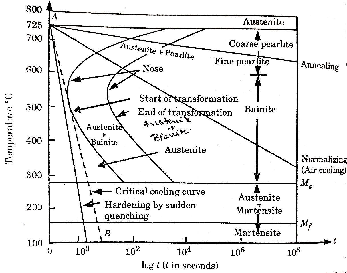
Figure 4: The TTT curve showing temperature and log (time) variation for a eutectoid steel, and its different phases.
Key Takeaways:
Importance of T-T-T Diagram:
It shows the structure that obtained at different cooling rates.
It graphically describes the cooling rate required for the transformation of austenite to pearlite, bainite or martensite.
It shows the time required for transformation to various phases.
4.5. Austempering:
It is very similar to martempering. Steel is austenitized and then quenched in a salt bath maintained at a constant temperature in the range of  .
.
The article is held at this temperature for long enough to allow isothermal transformation to be completed.
After the complete transformation of austenite to bainite, steel is cooled to room temperature in air. It is also called isothermal quenching.
The temperature of quenching lies below the nose of the TTT curve and above the  temperature.
Heat treatment cycle for austempering is shown in figure 5.
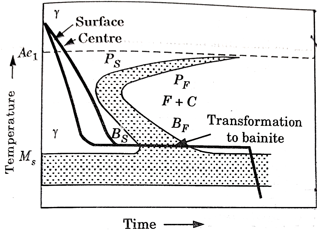
Figure 5: Heat Treatment cycle for Austempering
Key Takeaways:
The principal purpose of austempering is to obtain high impact strength and increased notch toughness at a given high hardness level.
4.6. Martempering:
This is a hardening method that produces martensite. This method is also known as hardening by interrupted quenching
First the steel is heated to the hardening temperature then quenched in a medium (salt bath) having a temperature slightly above the point where martensite starts to form (usually from  .
.
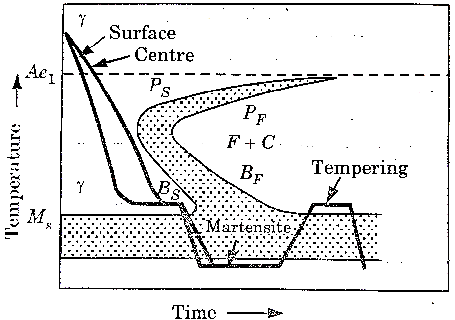
Figure 6: Heat Treatment cycle for martempering
It is held until it reaches the temperature of the medium and then cooled further to room temperature in air or oil. The holding time in quenching medium or bath should be sufficient to enable a uniform temperature to be reduced throughout the cross section but not long enough to cause austenite decomposition.
Austenite is transformed into martensite during the subsequent period of cooling to room temperature.
Key Takeaways:
This treatment provides a structure of martensite and retained austenite in the hardening steel.
4.6.1. Case Hardening (or Carburizing):
It is a process through which a hard, wear resistant and shock resistant surface is produced on steel, having a tough core inside.
In this process the steel is heated to red hot and then carbon contents are forced into its surface structure. It is then hardened as usual. For this reason this process is also frequently known as carburizing.
Case Hardening has following objectives:
Types of Carburizing (Case Hardening) Processes:
Pack Carburizing:
As name suggests it is a method in which components or specimen is packed in a steel box with carbon-rich powder of charcoal or coke in granules form. Then box is heated slowly above the lower critical temperature and soaking is done.
The depth of soaking depends on the time of exposure between steel and solid fumes. After soaking, box is then cooled slowly.
This method has disadvantages of scale formation at the surface of metal.
Liquid Carburizing:
In liquid carburizing, liquid carbon is used to impinge upon the heated steel by jets from nozzles. Due to this, carbon gets deposited on the steel.
This method has a disadvantage of scale formation at the surface of metal.
Gas Carburizing:
In this method, heating of steel is done in a carbon rich gaseous (as methane, propane, etc.) environment.
At high temperature, hydrocarbon gets decompose into carbon and hydrogen. This decomposed carbon gets deposited on the metal surface.
The thickness of hardened case can be controlled by rate of gas flow.
Nitriding:
This process is used to form a hard surface of nitride on the surface of metal (or steel). This is also, surface hardening process like carburizing.
This process consists of:
Heating of specimen below the lower critical temperature approximately up to 
Soaking is done in the atmosphere of ammonia ( . The nitrogen from
  penetrates into the surface of steel to form very hard nitride surface.
Nitriding improves corrosion resistance and provides hard surface after this process, there is no need of any heat treatment process. Disadvantage is only its cost and time consumption to complete the process.
Cyaniding:
In cyaniding we dipped the components in a bath of sodium cyanide (NaCN) at a temperature  . Soaking process is completed in the sodium cyanide (NaCN) bath.
After completion of soaking, metal or steel is quenched in oil (or water) to harden the surface.
The case contains about 4 to 4.5% Carbon and 0.5 to 3% nitrogen.
Cyaniding process is used to increase the fatigue strength of steel. It is less time-consuming process but a costly process.
Carbo-Nitriding:
In carbon-nitriding process both carbon and nitrogen are introduced on the surface of steel at the same time during heating process.
Heating is done in a temperature range  in an environment containing anhydrous ammonia and carbon thus carbide layer provides a prevention to the nitride layer.
After heating, quenching is done in a suitable medium. The surface hardness is much higher than the carburizing steel.
Flame and Induction Hardening:
Flame Hardening-
This process is based on rapid heating and quenching in order to produce a hard surface and soft core in the work.
An oxy-acetylene flame is used to heat the work above its critical temperature and quenching is done by means of a spray of water directed on the surface.
The torch for heating the work may be stationary or may move progressively over the work which may or may not spin as shown in figure 7.
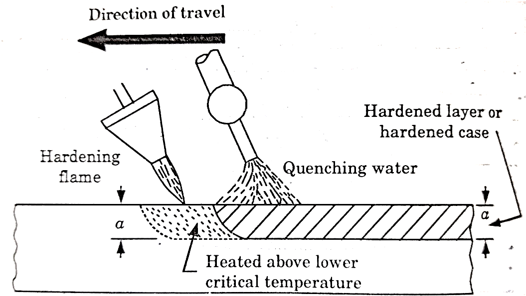
Figure 7: Flame Hardening
This method is applied for hardening cast gears, mill rolls or worms.
Induction Hardening-
It is a process of surface hardening in which the surface to be hardened is surrounded by copper inductor through which a high frequency current of about 2000 cycles per second is passed.
The inductor acts a primary coil of a transformer.
The work to be hardened is placed in the inductor in such a way that it does not touch the inductor as shown in fig.
The inductor block has a number of holes to spray water for quenching. The heating effect in the work is produced by the induced eddy currents and hysteresis loss in the surface of the work.
Key Takeaways:
Steels containing 0.35-0.55% carbon are most frequently induction hardened. The hardening temperature is above  (Curie point) in order to increase the depth of current penetration.
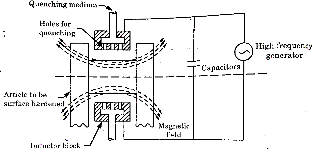
Figure 8: Arrangement for high- frequency induction heating
The heated areas are quenched immediately by water sprays directed from the inductor.
Induction hardening is, extensively used in many industrial plants.
4.7. Vacuum and Plasma Hardening:
4.7.1. Vacuum Hardening-
During vacuum hardening, material is heated in the absence of oxygen by convection in the medium of inert gas (N₂) and / or heat radiation in the under pressure. Steel is hardened with a stream of nitrogen; whereby cooling rate can be determined by selecting the excess pressure.
Advantages:
4.7.2. Plasma Hardening-
Plasma nitriding, known also as ion nitriding is a form of case hardening process. It is an extension of conventional nitriding process, utilizing plasma discharge physic to diffuse nitrogen into the surface of a ferrous alloy. Plasma nitriding can be further branched out into plasma nitro-carburising. In this process, carbon together with nitrogen was introduced into the metal surface. The harden case, which is the nitriding layer is commonly known as ‘diffused case’ or ‘diffusion zone’.
Plasma nitriding is achieved using a D.C glow discharge technology, whereby the nitrogen gas inside the furnace is converted into nitrogen ions and absorbed by the metal. Molecular nitrogen is first broken into atomic nitrogen through direct plasma dissociation.
N2 + e- → N + N + e-
Atomic nitrogen is then further converted into nitrogen ion through plasma ionization
N + e- → N+ + 2e-
The nitrogen ion, N+, will then diffuse into the metal surface as finely dispersed nitrides, imparting high hardness to the surface. Thus, case hardening is achieved. Plasma Nitriding.
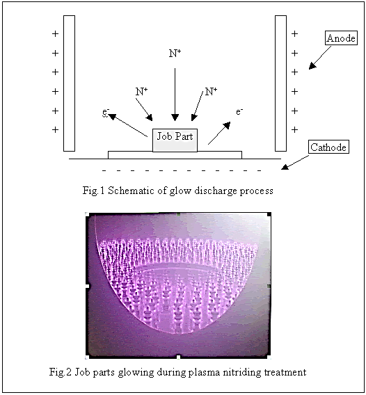
Figure 9: Plasma Nitriding Process
Key Takeaways:
In Plasma nitriding process, the job part and the cathode inside the furnace will be emitting a purple glow. This is because voltages had dropped sharply at these regions. This provided a large amount of discharged energy, which causes the cathode and job part to glow.
Reference: