The output signals from sensor of measurement system are generally need to be processed so it can be suitable for next stage. For example, if signal is to small it needs to be amplify, if it contains some disturbances (noise) which has to be removed, non-linear signal required to be linear be analogue have to be made digital or vice versa, be a resistance change and have to be made into a current change, be a voltage change and have to be made into a suitable size current change, etc. All these changes are referred to as signal conditioning.
Signal conditioning processes
Signal conditioning system enhances the quality of signal coming from a sensor in terms of:
- Protection: To protect the damage to the next element of mechatronics system such microprocessors from the high current or voltage signals. Thus, there can be series current limiting resistors, fuses to break if the current is too high, polarity protection and voltage limitation circuits
- Right type of signal: To convert the output signal from a transducer into the desired form i.e. voltage / current.
- Right level of the signal: To amplify or attenuate the signals to a right /acceptable level for the next element.
- Noise: To eliminate noise from a signal.
- Manipulation: To manipulate the signal from its nonlinear form to the linear form.
Following are some of the elements that might be used in signal conditioning
Operational amplifier
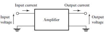
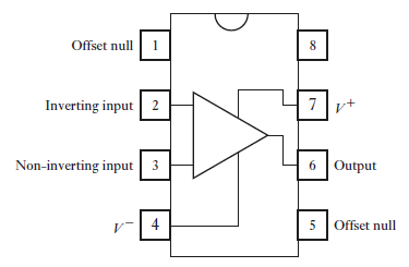
Amplifier is considering being essential system which have input and output as shown in figure 1. The ratio of output voltage to input voltage when each measured relative to earth is known as voltage gain. Input voltage is divided by input current is known as input impedance and when output voltage divided by output current is known as output impedance. Operational amplifier is basis of many signal conditioning modules. The operational amplifier is high gain d.c. amplifier. Operational amplifiers have gain of order of 100000 or more, that is supplied on integrated circuit in silicon chip. Operational amplifiers have two inputs one is inverting (-) and other is non-inverting (+). The output is depends connection to this input terminals. Operational amplifiers have other inputs too name negative voltage supply, positive voltage supple, and two offset null (figure 2) An ideal operational amplifier is as an amplifier with an infinite gain, infinite input impedance and zero output impedance, i.e., the output voltage is independent of the load.
|
Figure 1: Amplifier
|
Figure 2: Pin connections for a 741 operational amplifier
The followings are some types of circuits that might be used with operational amplifiers when used for signal conditioners.
Inverting amplifier
|
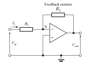
Figure 3: Inverting amplifier
Figure 3 shows connections made to amplifier when used as inverting amplifier. Input is supplied to inverting input terminal through resistance R1 and non-inverting terminal is ground. A feedback path is connected to inverting input via the resistor R2 from output. The operational amplifier has a voltage gain of about 100 000 and the change in output voltage is typically limited to about  10 V. The input voltage must then be between -0.0001 and +0.0001 V. This is virtually zero and so point X is at virtually earth potential. For this reason, it is called a virtual earth. The potential difference across R1 is
  Hence, for an ideal operational amplifier with an infinite gain, and hence
 , the input potential
  can be considered to be across R1. Thus
|
The operational amplifier has very high impedance between its input terminals; for a 741 about 2 MΩ. Thus, there is no virtually current flow through point X into it. This is the condition for an ideal amplifier i.e. have infinite impedance and no current flows through X. so current through R2 is current flows through R1 which is I1. Potential difference across R2 is since
since  =0
=0
Therefore, Potential difference across R2 is
The negative sign indicates that the output is inverted, i.e., 180° out of phase, with respect to the input. |
Non-inverting amplifier
Figure 4 shows operational amplifier as non-inverting amplifier. The output can be considered to be taken from across a potential divider circuit consisting of R1 in series with R2. The voltage VX is then the fraction R1/(R1 +R2) of the output voltage, i.e.
|
Since there is virtually no current through the operational amplifier between the two inputs there can be virtually no potential difference between them. Thus, with the ideal operational amplifier, we must have 
A particular form of this amplifier is when the feedback loop is a short circuit, i.e. R2=0. Then the voltage gain is 1. |
Summing amplifier
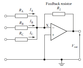
Figure 4 shows summing amplifier. Point X is a virtual earth.
The potential difference across R2 is
If
|
|
Figure 4: Summing amplifier
Protection
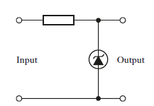
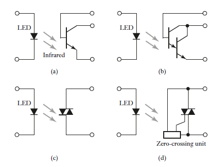
In many situations there is possibilities of damage in circuit where connection of sensor to next unit due high current or high voltage. Circuit can be protected against a high current by connecting a series of resistance to input to limit the current up to acceptable level and a fuse to break if current exceed a safe. Zener diodes can be used to protect against high voltage and wrong polarity (figure 5). Up to some breakdown voltage Zener diode behaves like ordinary diode and after breakdown they become conducting. If maximum allowable voltage is 5 V so Zener diode stop voltages above 5.1 V getting through, so Zener diode with a voltage rating of 5.1 V chosen. Zener diode breakdown and its resistance drop to a very low value when the voltage rises to 5.1 V. The result is that the voltage across the diode, and hence that outputted to the next circuit, drops. Because the Zener diode is a diode with a low resistance for current in one direction through it and a high resistance for the opposite direction, it also provides protection against wrong polarity. It is connected with the correct polarity to give a high resistance across the output and so a high voltage drop. When the supply polarity is reversed, the diode has low resistance and so little voltage drop occurs across the output. Optoisolator are used to complete breakdown isolate circuits completely and remove all electrical connections between them. An optoisolator is an electronic component that transfers electrical signals between two isolated circuits by using light. Figure 6 shows a number of forms of optoisolator.
|
Figure 5: Zener diode protection circuit.
|
Figure 6: Optoisolators: (a) transistor, (b) Darlington, (c) triac, (d) triac with zero-crossing unit.
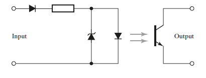
Optoisolator outputs can be used directly to switch low-power load circuits. Thus, a Darlington optoisolator might be used as the interface between a microprocessor and lamps or relays. To switch a high-power circuit, an optocoupler might be used to operate a relay and so use the relay to switch the high-power device. A protection circuit for a microprocessor input is thus likely to be like that shown in Figure 7; to prevent the LED having the wrong polarity or too high applied voltage; it is also likely to be protected by the Zener diode circuit shown in Figure 6 and if there is alternating signal in the input a diode would be put in the input line to rectify it.
|
Figure 7: Protection circuit
Filtering
Process of removing a certain band of frequencies from a signal and permitting others to be transmitted is known as filtering. There are some basic terms used in filtering:
Pass band: The range of frequencies passed by a filter is known as the pass band.
Stop band: The range frequencies not passed by filter is known as the stop band.
Cut-off frequency: Boundary of frequencies between stopping and passing known as the cut-off frequency.
Filter are classified according to their stopping and passing frequency range
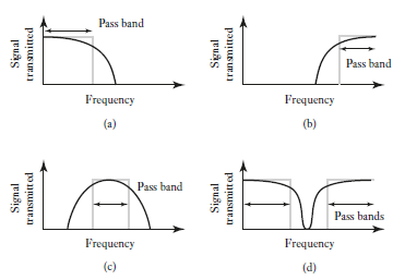
- Low-pass filter: A low-pass filter has a band which allows all frequencies from range of zero to some frequency to be transmitted (Figure 8a)
- High-pass filter: A high-pass filter has a pass band which allows all frequencies from some value up to infinity to be transmitted (Figure 8b
- Band-pass filter: A Band-pass filter allows all the frequencies within a specified band to be transmitted. (Figure 8c
- Band-stop filter: A band-stop filter stops all frequencies with a particular band from being transmitted. (Figure 8d)
In all cases the cut-off frequency is defined as being that at which the output voltage is
70.7% of that in the pass band. The ratio of input and output powers is known as attenuation this being written as the ratio of the logarithm of the ratio and so gives the attenuation in units of bels. Since this is a rather large unit, decibels (dB) are used and then attenuation in dB = 10 lg (input power/output power). Since the power through an impedance is proportional to the square of the voltage, the attenuation in dB = 20 lg(input voltage/ output voltage). The output voltage of 70.7% of that in the pass band is thus an attenuation of 3 dB.
|
Figure 8: Characteristics of ideal filters: (a) low-pass, (b) high-pass, (c) band-pass, (d) band-stop.
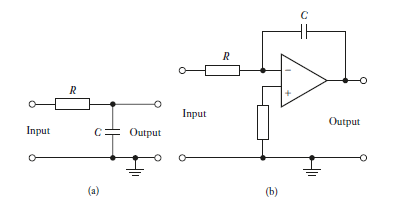
When filters are made up using resistors, capacitors and inductors are known as passive filters. When filters involve operational amplifier are known as active filters. Passive filters have the disadvantage that the current that is drawn by the item that follows can change the frequency characteristic of the filter. This problem does not occur with an active filter. Low-pass filters are very commonly used as part of signal conditioning. This is because most of the useful information being transmitted is low frequency. Since noise tends to occur at higher frequencies, a low-pass filter can be used to block it off. Thus, a low-pass filter might be selected with a cut-off frequency of 40 Hz, thus blocking off any interference signals from the a.c. mains supply and noise in general. Figure 9 shows the basic form that can be used for a low-pass filter.
|
Figure 9: Low-pass filter: (a) passive, (b) active using an operational amplifier.
Actuators
Actuation system is element of control system which is responsible for transforming output from control system into a controlling action on machine. For example, electrical output from the controller which has to be transformed into a linear motion to move a load.
Pneumatic and hydraulic actuation system
Pneumatics is the term used when compressed air is used and hydraulics when a liquid, typically oil.
Pneumatic signals are used to actuate large valves and other high-power control devices and so move significant loads. The main drawback with pneumatic systems is compressibility of air. Hydraulic systems are used for higher power control devices. Main drawback for hydraulic are they are more expensive than pneumatic systems and oil leaks which do not occur with air leaks. The atmospheric pressure varies with both location and time but in pneumatics is generally taken to be  Pa, such a pressure being termed 1 bar.
Hydraulic system
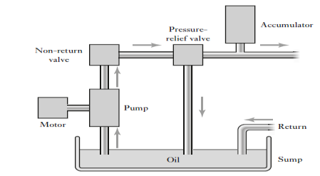
In hydraulic system pressurised oil is supplied through pump driven by electric motor. The pump pumps the oil from sump through non-return valve and accumulator to system from which it returns back to sump. Systematic arrangement is shown in figure 10. Pressure relief valve us also used to release the pressure if it exceeds the safety level. Non-return valve prevent oil returning pump and accumulator is used to minimise fluctuations in output oil pressure.
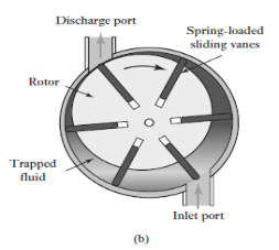
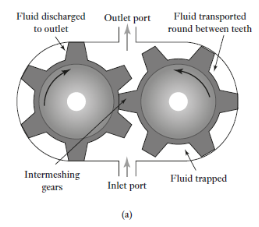
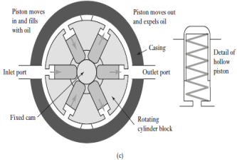
Most widely use hydraulic pumps are gear pump, vane pump and piston pump. The gear pump consists of two close-meshing gear wheels which rotate in opposite directions (Figure 11(a)). Fluid is forced through the pump as it trapped between the rotating gear teeth and the housing of pump and is transferred from the inlet port to outlet port. Gear pumps are widely used because they are low in cost and robust. They generally operate at pressures below about 15 MPa and at 2400 RPM. The maximum flow capacity is about 0.5  . Main drawback of these pumps is, leakage occurrences between the teeth and the casing and between the interlocking teeth, causing effect efficiency of pump. The vane pump consists of spring-loaded sliding vanes slotted in a driven rotor (Figure 11(b)). As the rotor rotates, the vanes adjust to the contours of the casing. Water is trapped between vanes and casing and then guided from inlet port to outlet port. The leakage for vane pump is less as compared to gear pump. There are many forms are available for piston pumps used in hydraulics. Radial piston pump (Figure 11(c)), a cylinder block rotates round the stationary
|
Figure 10: Hydraulic power supply
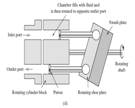
cam and causing hollow pistons, with spring return mechanism, to move in and out thus fluid is drawn in from the inlet port and transported round for ejected from the outlet port. The axial piston pump (Figure 11(d)) has pistons which move axially. The pistons are arranged axially in a rotating cylinder block and moved by contact with the swash plate. Swash plat is at an angle to the drive shaft and thus as the shaft rotates, they move the pistons so that air is sucked in when a piston is opposite the inlet port and expelled when it is opposite the discharge port. Piston pumps have a high efficiency and can be used at higher hydraulic pressures than gear or vane pumps.
|
|
Figure 11: (a) Gear pump, (b) vane pump, (c) radial piston pump, (d) axial piston pump with swash plate.
Pneumatic systems
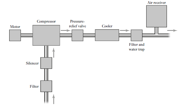
Pneumatic power supply (Figure 12) consists of an electric motor which drives the air compressor. The air inlet air compressor is filtered and noise level is reduced via a silencer. A pressure-relief valve is used for protection against the pressure in the system rising above a safe level. Cooling system is used to cool down air temperature and a filter with a water trap is used to remove contamination and water from the air. An air receiver is used to increases the volume of air in the system and minimise any short-term pressure fluctuations. Commonly used air compressors are ones in which successive volumes of air are isolated and then compressed.
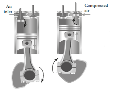
Figure 13 shows the basic form of a single acting, single-stage, vertical, reciprocating compressor. On the air intake stroke, piston moves downward causes air to be sucked into the chamber through the spring-loaded inlet valve and when the piston move upward, the trapped air forces to close inlet valve and so becomes compressed. When the air pressure has risen sufficiently, the spring-loaded outlet valve opens and the trapped air flows into the compressed-air system. After the piston has reached the top dead centre it then begins to descend and the cycle repeats itself. Such a compressor is termed single-acting because one pulse of air is produced per piston stroke; double-acting compressors are designed to produce pulses of air on both the up and down strokes of the piston. For the production of compressed air at more than a few bars, two or more stages are generally used. Normally two stages are used for pressures up to about 10 to 15 bar and more stages for higher pressures. Reciprocating piston compressors can be used as a single-stage compressor to produce air pressures up to about 12 bar and as a multistage compressor up to about 140 bar.
|
Figure 12: Pneumatic power supply
Typically, air flow deliveries tend to range from about 0.02  free air delivery to about 600
  free air delivery; free air is the term used for air at normal atmospheric pressure.
|
Figure 13: Single-acting, single stage, vertical, reciprocating compressor
Valves
Valves are used with hydraulic and pneumatic systems to direct and regulate the fluid flows. There are two forms of valve
- finite position valves: The finite position valves are used for to allow or block fluid flow and so can be used to switch actuators on or off. These valves are also used for directional control i.e., to switch the flow from one path to another
- infinite position valves: The infinite position valves are able to control flow anywhere between fully on and fully off and so are used to control varying actuator forces or the rate of fluid flow for a process control situation.
Electrical actuation system
For position or speed control system electric motors are frequently used. A force is exerted on conductor in magnetic field when a current pass thought it. This is basic principle of motors working. F=BIL
Where
F=force, B= flux density, I= current in magnetic field, L= length of conductor.
D.C. Motors
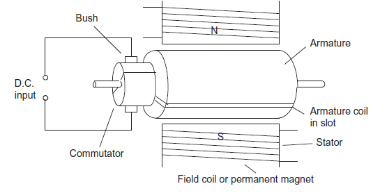
In the d.c. motor, coils of wire are mounted in slots on a cylinder of magnetic material called the armature. The armature is mounted on bearings and is free to rotate. It is mounted in the magnetic field produced by field poles. This magnetic field might be produced by permanent magnets or an electromagnet with its magnetism produced by a current passing through the, so-termed, field coils. Whether permanent magnet or electromagnet, these generally form the outer casing of the motor and are termed the stator. Figure 14 shows the basic elements of d.c. motor with the magnetic field of the stator being produced by a current through coils of wire. In practice there will be more than one armature coil and more than one set of stator poles. The ends of the armature coil are connected to adjacent segments of a segmented ring called the commutator which rotates with the armature. Brushes in fixed positions make contact with the rotating commutator contacts. They carry direct current to the armature coil. As the armature rotates, the commutator reverses the current in each coil as it moves between the field poles. This is necessary if the forces acting on the coil are to remain acting in the same direction and so continue the rotation.
|
Figure 14: Basic elements of a d.c. motor
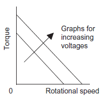
For a d.c. motor with the field provided by a permanent magnet, the speed of rotation can be changed by changing the size of the current to the armature coil, reversing the current in the armature coil can change the direction of rotation of the motor. Figure 15 shows how, for a permanent magnet motor, the torque developed varies with the rotational speed for different applied voltages. The starting torque is proportional to the applied voltage and the developed torque decreases with increasing speed.
D.C. motors classified as series, shunt, compound and separately excited according to how
the field windings and armature windings are connected.
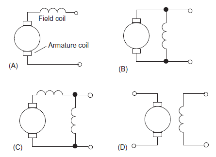
1. Series-wound motor: The armature and field coils are in series (Figure 16 A). Motor exerts the highest starting torque and greatest no-load speed. But with light loads there is a possibility series-wound motor will run at too high a speed. No effect on the direction of rotation of the motor if the polarity of the supply to the coils is reversed, since both the current in the armature and the field coils are reversed.
2. Shunt-wound motor: With the shunt-wound motor (Figure 16 B) the armature and field coils are in parallel. Shunt-wound motor have the lowest starting torque, lower no-load speed but has good speed regulation. Shunt-wound motor have constant speed without consideration of load and thus shunt-wound motors are very widely used. To reverse the direction of rotation, either the armature or field current can be reversed.
3. Compound motor: The compound motor (Figure 16 C) have two field windings, one in series with the armature and one in parallel. Compound-wound motors have high starting torque and good speed regulation.
4. Separately excited motor: The separately excited motor (Figure 16D) have separate control of the armature and field currents. The direction of rotation of the motor can be obtained by reversing either the armature or the field current.
|
Figure 15: Permanent magnet motor characteristic
|
Figure 16: (A) Series, (B) shunt, (C) compound, and (D) separately wound
Stepper Motor
For each digital pulse supplied to its input the stepper or stepping motor rotates through equal angles. For example, if 1 input pulse produces a rotation of 1.8 then 20 input pulses will produce a rotation through 36
 , 200 input pulses a rotation through one complete revolution of 360
 . Stepper motor can be used for accurate angular positioning. To drive a continuous belt, the angular rotation can be transformed into linear motion of the belt and so accurate linear positioning can be achieved. Such a motor is used with computer printers, x-y plotters, robots, machine tools and a wide variety of instruments for accurate positioning.
There are two types of stepper motor,
- Permanent magnet type with a permanent magnet rotor and the
- Variable reluctance type with a soft steel rotor.
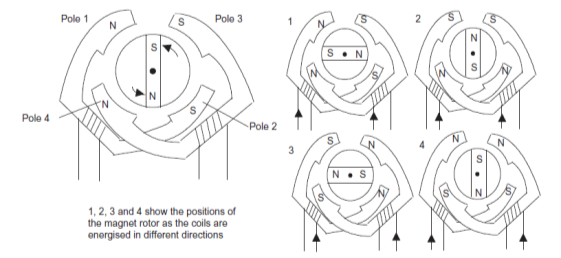
Figure 17 shows the basic elements of the permanent magnet type with two pairs of stator poles. Poles of the permanent magnet motor can be activated by a current passing through the field winding, the coils being such that opposite poles are produced on opposite coils. The current is supplied from a d.c. source to the windings through switches.
|
Figure 17: The basic principles of the permanent magnet stepper motor (2-phase) with 90 steps.
References:
1. Instrumentation and control systems by W. Bolton, 2nd edition, Newnes, 2000
2. Thomas G. Beckwith, Roy D. Marangoni, John H. Lienhard V, Mechanical Measurements (6th Edition) 6th Edition, Pearson Education India, 2007
3. Gregory K. McMillan, Process/Industrial Instruments and Controls Handbook, Fifth Edition, McGraw-Hill: New York, 1999.
