UNIT 1
Introduction to fluid machinery
The fluid machines can be broadly classified into 2 main categories, namely power consuming and power producing machines.
In case of power producing devices, the energy of the working fluid is converted into mechanical power. Example: - reciprocating engines and turbines. While in power absorbing devices, the mechanical power supplied at the input shaft is utilized and transfer to the working fluid either in the form of pressure energy or kinetic energy or both. Example: - Pumps, fans, compressors, etc.
Both these types of machines use liquid as working fluid in case of hydraulic machines and gases or vapour in case of thermal machines.
- Reciprocating machines :-
They operate on the principle of positive displacement of the fixed amount of working fluid in piston cylinder arrangement. The working fluid undergoes change in pressure due to change in volume during the reciprocating motion of the piston.
Examples of power producing reciprocating machines are internal combustion engines, reciprocating steam engines and examples for power absorbing reciprocating machines are Reciprocating pumps and reciprocating compressors.
2. Turbomachines: -
These are Rotary type of machines in which the energy transfer is brought about by dynamic action of rotating elements.
In these machines the fluid is not positively contained but it continuously flows steadily through the machine. The energy transfer in these machines takes place due to dynamic effect.
Examples of power producing turbomachines are wind, hydraulic, Steam and gas turbines.
Examples of power consuming turbomachines are centrifugal pumps, fans, blowers and compressors.
1 Based on working medium
A) Using air or gases or vapour. These are called thermal or pneumatic turbomachines.
B) Using liquids. These are hydro turbomachines.
2 According to energy conversion
A) Power producing devices which convert energy of fluid into mechanical work
B) Power absorbing devices which convert mechanical energy into pressure or kinetic energy
3 According to direction of flow
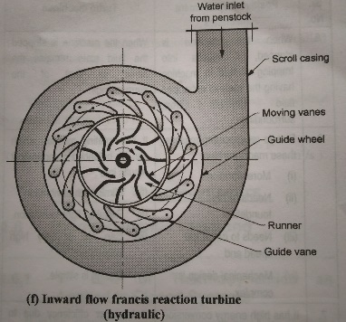
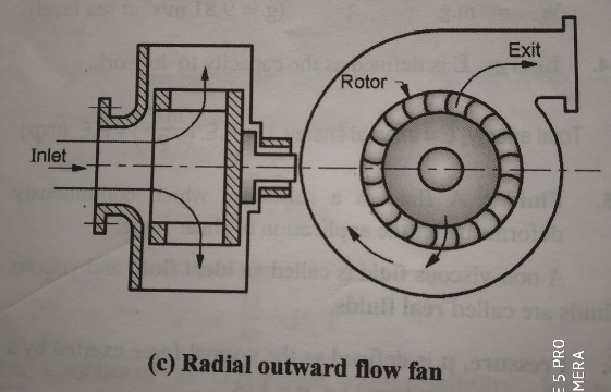
a) Radial flow. There is substantial change in radius during fluid flow. Thus, there is change in energy due to change in radius. These maybe inward or outward flow machines. Example: - Francis turbine.
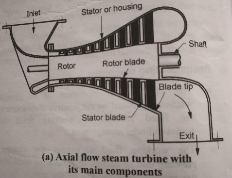
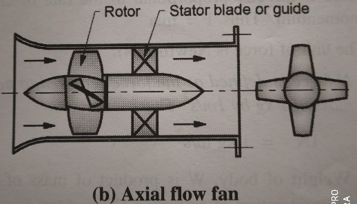
b) Axial flow. They have no significant change of radius during fluid flow at entry and exit.
Example: - axial flow pumps and turbines, windmills
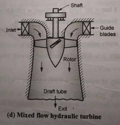
c) Mixed flow. They have mixed fluid flow that is both axial and radial flow.
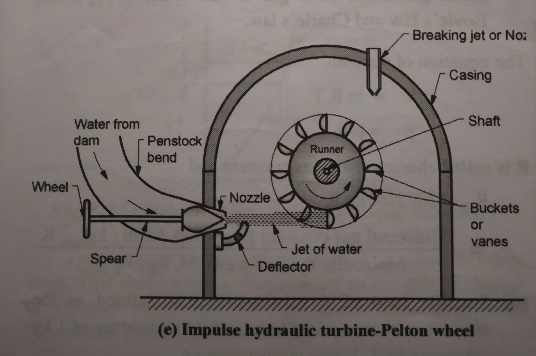
d) Tangential flow Example: - impulse hydraulic turbine
4 According to action of fluid on the rotor vanes
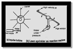
a) Impulse machines which work on principle of impulse. A machine in which there is no change in static head or static pressure in the rotor is called impulse machine. The degree of reaction of impulse machines is 0. Therefore, in these types of machines, velocity at inlet is equal to velocity at outlet and the energy transfer is purely due to change in absolute kinetic energy of the fluid passing over the rotor. In other words, energy transfer in these machines is purely due to dynamic action of fluid. Example: - Pelton Wheel.
b) Reaction machines which work on principle of reaction. In a pure reaction machine, the degree of reaction R is equal to 1. In such a machine the energy transfer is by virtue of change of static pressure in the router and eventually V1 is equal to V2. However, the absolute velocity at inlet and outlet may not be equal due to which the degree of reaction turbine is usually less than one. Reaction machines with any degree of reaction must have an enclosed rotor because the fluid cannot expand freely in any direction. A simple example of a reaction machine would be a lawn sprinkler. In this the water enters the nozzles under high pressure or high head. High pressure is converted into velocity head in nozzle. The high velocity jet leaves the rotor in tangential direction. The change in momentum of the fluid in nozzle which is free to rotate gives rise to reactive force hence it is reactive type of simple machine.
- Vanes mounted on rotating element called an impeller or rotor or runner. Term impeller is used in case of centrifugal pumps and compressors, runner is used for radial flow hydraulic turbines, rotor is used in case of axial flow gas turbines and steam turbines.
- Stationary element or guide vanes or nozzles are used for controlling the flow direction of fluid for energy conversion process without any pressure changes except in case of nozzles. Stationary element is not a necessary component of every Turbo machine.
- A shaft, either an input shaft or an output shaft or both.
- A housing or casing. It does not play a direct part in energy conversion process. It is only used to restrict the flow and to direct the fluid flow in a particular direction
- Diffuser it is a passage of increasing cross sectional area in the direction of fluid flow. Its function is to convert the kinetic energy of fluid into pressure energy.
- Draft tube. Similar in action to a diffuser it is placed at the outlet of a hydraulic reaction turbine.
The momentum of fluid is defined as the product of mass and its velocity. Therefore,
Momentum M = Mass, m X Velocity, C --------- (1)
According to Newton's second law of motion the rate of change of momentum is directly proportional to external force acting on the body.
F α dM/dt
F = gc X dM/dt ---------(2)
Where, gc is the constant of proportionality
From (1) and (2) and product rule of differentiation, we can substitute and rewrite (2) as
F = d (m.C)/dt = [m.dC/dt + C.dm/dt]
In hydrodynamic machines, dm/dt = 0, since there is no change in mass with respect to time.
F = m.dC/dt = m.a ----------(3)
Where, acceleration a = dC/dt.
Consider a rotor rotating at an angular speed of Ω rad/s
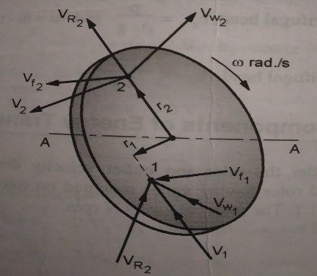
Consider points one and two on the rotor at radii r1 and r2. As in that the fluid enters at point 1 and leaves at point 2.
Let, m = mass flow rate of fluid in kg per second
V1 = absolute velocity of fluid at point 1 in meters per second
V2 = absolute velocity of fluid at point 2 in meters per second
V1 = Vf1 + VR1 + Vw1
V2 = Vf2 + VR2 + Vw2
The energy transferred between the fluid and machine is only due to change in momentum caused by tangential component of velocity.
Therefore, the rate of change of momentum between points 1 and 2
= m Vw1 - m Vw2
The momentum at point 1 = m Vw1 r1
The momentum at point 2 = m Vw2 r2
This rate of change is momentum represent torque produced on the rotor.
Torque, T = rate of change of angular momentum
= m Vw1 r1 - m Vw2 r2
= m (Vw1 r1 - Vw2 r2 )
Some of the major applications of turbomachines are given below.
- In steam power plants which uses turbines to convert the thermal energy of steam generated in boiler into mechanical power to drive an electric generator. Many pumps are used to handle water have boiler feed pump, condensate pump and cooling water circulating pumps. Blowers are used to supply air on the grate of the boiler.
- Gas turbine power plants are used for power generation and in aircraft applications for power generation and air conditioning of aircraft. It uses both gas turbine for conversion of thermal energy of gas into mechanical power and compressors to raise the pressure of the surrounding air to be supplied to combustion chamber. Turbochargers are used for supercharging of IC engines. Gas turbine power plants are also used for marine applications and military tanks.
- Various industries use pumps, blowers and compressors for fluid handling systems.
- Compressors are used to operate pneumatic tools.
- Centrifugal vapour compressors are used in large conditioning systems.
- Compressed air is also used to convey materials like sand and concrete in pipeline.
- Pneumatic motors are used to drive the mining machinery.
- Compressors and blowers are used in blast furnaces.
References: -
1. G. T. Mase, R. E. Smelser and G. E. Mase, Continuum Mechanics for Engineers, Third
Edition, CRC Press,2004.
2. Y. C. Fung, Foundations of Solid Mechanics, Prentice Hall International, 1965.
3. Lawrence. E. Malvern, Introduction to Mechanics of a Continuous Medium, Prentice Hall
International, 1969.
4. Hydrantic Machine by Jagdish Lal
5. Hydraulics & Hydraulic Machines by Vasandari
6. Hydrantic Machine by RD Purohit


