Unit 4
Hydraulic turbines
A hydraulic turbine is a machine which converts the pressure and kinetic energy of water called hydraulic energy into mechanical energy. These are also called as water turbines. The mechanical energy of turbine is further converted into electric energy by an electric generator which is directly coupled to the shaft of hydraulic turbine. The electrical power generated is known as hydro-electric power
Hydraulic turbines are efficient. These have low wear and tear and ease of maintenance. However, their capital cost is high with long gestation period due to the requirement of constructing the dam across the river and laying the long pipe lines.
According to the type of energy available at inlet to the turbine
An impulse turbine, as the name suggests, works on the principle of impulse. In these turbines, the head or pressure energy of water is first converted into kinetic energy by means of a nozzle or set of nozzles kept close to the runner. This high velocity jet produced by nozzle is allowed to impinge on the set of buckets fixed on the outer periphery of the wheel or runner. The direction of jet is changed by buckets. The change of momentum of water causes the wheel to rotate, thus produces mechanical energy.
It should be noted that the pressure water is atmospheric and remains constant while passing over the runner Examples of important impulse turbines are Pelton wheel, Girard turbine, Turgo turbine etc.
2. Reaction turbines
In these turbines, a part of pressure energy is first converted into kinetic energy before supplied to runner. Turbine is to run in closed passages which are completely filled with fluid supplied to runner Therefore, the water enters the runner having partly the pressure energy and partly the kinetic energy and both these energies are reduced simultaneously while passing over the runner and produce mechanical energy. Hence, these turbines work on the principle of impulse-reaction.
The runner of these turbines being under pressure above atmospheric, it requires the blades of turbine to run in closed passages which are completely filled with water in all conditions. Examples of reaction turbine is Francis, Kaplan and Propeller turbines.
According to direction of flow through runner Tangential flow turbine in which water flows
(i) Tangential flow turbines in which water flows tangent to the runner.
(ii) Radial flow turbines in which the water flows in the radial direction through the runner.
(iii) Axial flow turbines in which the water flows through the runner along the direction parallel to the axis of rotation of runner.
(iv) Mixed flow turbines in which water flows in the runner in radial direction but leaves in axial direction.
According to the head available at inlet to the turbine
(i) Low head turbines (2 m to 15 m)
(ii) Medium head turbines (16 m to 70 m)
(iii) High head turbines (71 m and above)
According to the specific speed (Ns) of the turbine
(i) Low specific speed.
(ii) Medium specific speed.
(iii) High specific speed.
Fig below shows a general layout of a hydro-electric power plant. It has the following main components.
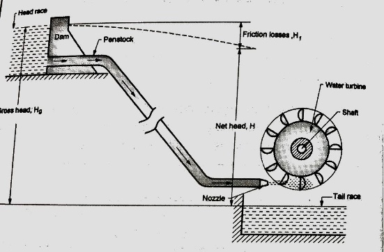
Net head, H =Gross head Hg - Frictional head, Hf
Frictional head from Darcy Weisbach equation is given as
H = (4 f L V2)/ (d 2g)
where,
f = Friction factor
L = Length of pipe
V = Velocity of flow of water
d = Diameter of pipe.
Pelton Wheel:
Pelton Wheel is a tangential flow impulse turbine. The water strikes the buckets along the tangent of the runner or wheel. It is used for the high heads more than 100m of water. These turbines have been used up to heads as high as 1600m.
Construction and Working of Pelton Wheel
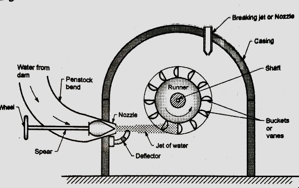
The water from the reservoir flows through the penstock to the nozzle which converts the pressure energy into kinetic energy. The resultant high velocity jet from nozzle strikes the buckets or vanes fitted at outer periphery of runner. The main components of the Pelton wheel are:
The needle spear is provided in the nozzle to regulate the water flow through the nozzle. Also, it provides smooth flow of water with negligible loss of energy. Spear is a conical needle which can be moved in axial direction by operating the wheel either manually or automatically. When the spear is moved in forward direction into the nozzle, it reduces the nozzle exit area, hence, the quantity of water flow striking the buckets is reduced. If the spear is moved backwards, it increases the flow rate of water. The nozzle converts the potential energy of water into kinetic energy before jet strikes the buckets. Pressure at exit of nozzle is reduced to atmospheric pressure.
2. Runner and Buckets
The turbine rotor called runner is a circular disc fixed with buckets. It is provided with cylindrical boss and keyed to the supporting shaft in small thrust bearings. The runner carries cup-shaped buckets more that I5 in number which are mounted at equidistance around its periphery. The buckets are either cast integrally with the circular disc or these are bolted individually to the runner, it helps in easy replacement of buckets when worn out. Buckets are made of cast iron, cast steel, special steel or stainless steel with inner surface polished to reduce friction losses of water jet. Type of metal used for bucket depends on the head at turbine inlet. The shape of the bucket is of double Hemispherical cup or bowl. Each bowl of the bucket is separated by a wall called splitter or a ridge.
The shape and dimensions of a bucket are shown in figure given below. The commonly adopted dimensions of bucket are:
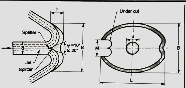
D = Diameter of jet
L = Length of height of bowl inside the rim = 2d to 3d
B= Width of bucket between the rim of bowl = 3d to 4d
T = Depth of bowl = 0.27 B to 0.32 B
M = Notch width = 1.1 d to 1.2 d
Splitter angle, ψ = 10° to 20°
The water strikes the bucket at the splitter which splits the water into two equal streams of the hemispherical bowl. The maximum force will be obtained when the jet is deflected through 180° into exact hemispherical bowl. However, in practice the jet is deflected through 160° to 170° (splitter angle ψ = 10° to 20°). It avoids striking the exit jet with the back of the succeeding bucket, thus exerting a retarding force on it. It would reduce the power output and the overall efficiency of turbine. This also avoids the splashing of water with a splitter. Pelton wheel is provided with two hemispherical cups since the splitter splits the jet into two equal streams, the axial component of each stream velocity is equal and opposite due to which the axial thrust on the shaft is negligible. Therefore, Pelton wheel needs very small thrust bearings. An undercut is provided and surface of spoons is raised so that water can be deflected back through the angle of 160° to 170° with the vertical without disturbing the incoming bucket.
3. Casing
A casing does not have any hydraulic function to perform therefore it is not actually needed in case of impulse turbines because the runner runs under atmospheric pressure. However, a casing is provided to prevent the splashing of water and lead the water to tail race, and to safeguard the persons against accidents. It is made of cast iron in two halves.
4. Braking Jet
Whenever the turbine is brought to rest, the nozzle is completely closed by pushing forward the spear. However, the runner continues to rotate due to its inertia for a considerable period of time till it comes to rest. In order to bring the runner to stop in a shortest time, a small nozzle is provided which issues the water jet and falls on the back of buckets. It acts as a hydraulic brake for reducing the speed of runner.
5. Deflector
A deflector is provided which is hinged to the casing to deflect the jet of water away from striking the buckets in case the load on turbine suddenly reduces. It prevents the runner to attain unsafe speeds. A governing mechanism is also provided to control the speed of turbine according to variation in load which we will see in detail at later stage in this module.
Work Done and Efficiency of the Pelton Wheel
A jet of water strikes the bucket at its splitter. It splits the jet into two parts, each part of jet glides over the inner surface of the cup and leaves the outer tips of the bucket G-G1. The jet of water striking the splitter gets deflected through an angle (180 - Φ). Inlet and outlet velocity diagrams can be drawn as explained in theory of jet and it is shown in figure below for slow speed runner.
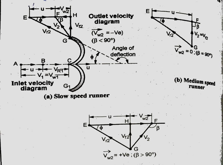
Figs (b) and (c) show the velocity diagram for medium speed and high-speed runners respectively,
Let d = diameter of jet in meters.
A = cross-sectional area of jet
Q = discharge rate, m3 /s
D = mean pitch diameter of runner,
N = speed of runner in r.p.m.
H = net head acting on Pelton wheel
Velocity of jet at inlet,
V1 = Cv √(2gH) (1)
where Cv is the coefficient of velocity of jet, its value varies from 0.91 to 0.99.
Blade velocity, u =πDN/60 (2)
Inlet velocity diagram
The Pelton wheel is a tangential flow turbine. The blade speed at inlet and outlet is same.
Therefore, u =u1 = u2; α = 0; Bucket inlet angle, θ = 0.
Therefore, inlet velocity diagram is a straight line where
Vr1 = V1 - u
Vw1 = V1 (i)
Outlet velocity diagram
Relative velocity at outlet Vr2 = K Vr1 where K is called friction factor. Its value is slightly less than unity and it is taken as one for a highly polished surface (neglecting friction).
Depending upon the speed of runner, various outlet velocity diagrams are drawn in Fig.
Vw2 = Vr2 cos Φ - u = (KVr1 cos Φ - u) (ii)
Mass flow rate of water,
mf = ρ. Q= ρ AV1 (3)
Fx = mf (Vw1 + Vw2) (iii)
Considering slow speed runner when β < 90°, Vw2 is negative, therefore,
Fx = mf (Vw1 + Vw2) (4)
b. Work done by jet on runner per second, W
W = Fx u = mf (Vw1 + Vw2) u (5)
c. Power developed, P
Here, Power developed is nothing but same as work done per second
P = W = mf (Vw1 + Vw2) u (6)
d. Hydraulic Efficiency, ηh
It is defined as the ratio of power delivered by runner to the power supplied at inlet. The power supplied at inlet is also called water power which is equal to kinetic energy of jet supplied to runner.
Kinetic energy supplied to jet per second = ½ mf V12 .
Hydraulic efficiency,
ηh = WD per second / KE supplied jet per second
= {mf (Vw1 + Vw2) u} / {½ mf V12}
= (2/V12){(Vw1 + Vw2) u} (7)
Sometimes, the hydraulic efficiency is also called as bucket efficiency.
e. Condition for maximum hydraulic efficiency, ηh
From the inlet velocity diagram
Vr1 = V1 - u
Vw1 = V1
From outlet velocity diagram
Vw2 = Vr2 cos Φ - u = (KVr1 cos Φ - u) = K (V1 - u) cos Φ - u
On substituting values of Vw1 and Vw2 in equation (7)
ηh = (2/V12){(Vw1 + Vw2) u}
= (2/V12){(V1 + K (V1 - u) cos Φ - u) u}
= (2/V12){(V1 - u + K (V1 - u) cos Φ) u}
= (2/V12) (V1 - u) {1+ K cos Φ} u (8)
The efficiency will be maximum when the differentiation of efficiency wrt blade velocity is equal to 0.
dηh / du = 0
D/du [(2/V12) (V1 - u) {1+ K cos Φ} u] = 0
(2/V12) {1+ K cos Φ} d / du [(V1 -u) u] = 0
d / du [(V1 -u) u] = 0
V1 - 2u = 0
V1 = 2u or u = V1 / 2 (9)
On substituting the above found value in (8),
We have, ηhmax = (2/V12) (V1 - V1 / 2) {1+ K cos Φ} V1 / 2.
= [1 + cos Φ] / 2 (if k =1) (10)
f. Mechanical efficiency, ηm :
It is defined as the ratio of power available at turbine shaft to the power developed by runner.
Difference of these two powers is due to mechanical losses caused by friction between mating parts (e.g. in shaft and runner, bearings etc).
So, ηm = (power available at turbine shaft, Ps) / (power developed by runner, P) (11)
g. Volumetric efficiency, ηv :
It is defined as the ratio of the volume of water actually striking the buckets to the volume of water issued by the jet. Hence,
Volumetric efficiency, ηv = Actual volume of water striking the bucket, Qa / Volume of water issued by the Jet, Q (12)
Volumetric efficiency is less than 100% since some quantity of water misses the bucket and directly passes to tail race without doing any useful work. Volumetric efficiency for Pelton wheel ranges from 97% to 99%.
h. Overall efficiency, ηo :
It is defined as the ratio of power available at turbine shaft to the power supplied by the water jet. Accordingly, ηo = Power available at turbine shaft, Ps / Power available the water jet, Pi (13)
Pi = ρ g Q H
ηo = ηv x ηh x ηm (14)
If a generator of efficiency ηg is connected to turbine in hydro-electric plant. Then,
Plant efficiency, ηp = Power output from generator, Pg / Power supplied by the jet, Pi
We have already discussed that in case of impulse turbines the total head available is first converted into velocity head in nozzles before the water enters the runner. Whereas, in case of reaction turbines only a part of total available head is converted into velocity head while passing over the fixed guide vanes before it enters the runner. Therefore, in reaction turbine the water enters the runner under pressure having some velocity head. While the water passes over the runner, its pressure is gradually converted into velocity head until its pressure is reduced to atmospheric pressure along with the change in kinetic energy based on its absolute velocity.
The reaction due to pressure difference and the impulse action is responsible for rotation of runner and producing the mechanical work. Therefore, these turbines are basically impulse-reaction turbine called reaction turbine. Pure reaction turbines are not built.
Since the water flows under pressure over the runner, above atmospheric, it is necessary that the runner must run full of water. The water from runner is discharged into tail race through a closed tube of gradually increasing cross sectional area called a draft tube. Also, the cross-sectional of flow through the passages of runner must gradually increase to accommodate the change in static pressure of water. The reaction turbines are suitable for low and medium heads ranging from 30 m to 250 m of head some of the important reaction turbines are: Fourneyron, Francis, Kaplan and propeller turbines.
Classification of Reaction Turbines
According to the direction of flow of water through the runner
In a radial flow turbine, the water flows along the radial direction in the runner. It may be an inward flow type or outward flow type.
In an inward flow turbine, the water enters at the outer periphery of the runner and flows radially inwards towards the center of runner e.g. old Francis turbine, Girard radial flow turbine etc. In an outward flow turbine, the water enters at the center of runner and flows radially outward towards the outer periphery of the runner. e.g. the Fourneyron turbine.
2. Axial flow turbines
Axial flow turbines are also called as parallel flow turbines. In these turbines the water enters and leaves the runner along the direction parallel to the axis of the shaft. Some examples of axial flow turbine are Kaplan and propeller turbines, Girard axial flow turbine, Jonal turbine etc.
3. Mixed flow turbines
In mixed flow turbine the water enters at the outer periphery of runner in radial direction and leaves at the center in the direction parallel to the axis of rotation of runner. Modern Francis turbine is the example of mixed flow turbine.
According to available head and discharge
Impulse turbines are used for high heads above 250 m whereas the reaction turbines are used for low and medium heads. Therefore, reaction turbines based on head and discharge are classified as:
Constructional Features of Reaction Turbine (Francis Turbine)
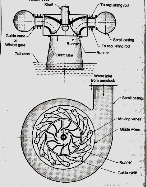
Water from penstock flows into the outer scroll casing of turbine which is made in spiral shape, the casing surrounds the guide vanes, the runner, the shaft etc. The casing and runner always run full of water. The cross section of the casing is made of decreasing area so that the water is evenly distributed around the circumference of runner almost at constant velocity and pressure. The material used for casing of a reaction turbine depends on the head it works. The casing is usually made of concrete for less than 30 m head, of welded rolled steel plates up to 100 m head and of cast steel for more than 100 m head. In large units, stay vanes are provided inside the casing to support it. Stay vanes also help in guiding the water from casing to guiding vanes so that water is equally distributed around the periphery without formation of any eddies.
2. Guide Mechanism
It consists of a stationary ring in the form of a wheel called guide wheel. It surrounds the outer periphery of runner and is fixed to inner surface of casing. In between the outer and inner ring of guide wheel, it carries a series of guide vanes or wicket gates of aero foil section. These vanes form the number of passages between the casing and runner blades. Though these vanes are fixed in position but they can be rotated about their respective pivots.
The guide vanes have the following functions to perform:
It is achieved by swinging the guide vanes about their own pivots by opening or closing the guide vane passages. Swinging action of guide vanes is achieved by governing mechanism.
3. Runner and shaft
The runner is keyed to the main shaft of the turbine. Shaft may be horizontal or vertical, accordingly the turbines are called horizontal turbines and vertical turbines. The shaft is made of steel and it is supported in thrust bearings. The runner consists of suitable designed blades of aero foil section so that the water enters and leaves the blades without shock. The number of blades usually vary between 16 to 24. The surfaces of moving vanes are made very smooth to reduce friction losses. The runners are made of cast iron for low head turbines and it is made of stainless steel for high head turbines.
4. Draft Tube
Water passing over the runner blades is discharged to tail race through a gradually increasing area, called draft tube. The small end of draft tube is fixed to outer opening of the casing and its bigger end is deeply submerged into tail race by at least 1 m depth from tail race level. It is evident from discussion that the entire passages of a reaction turbine from head race to tail race are totally enclosed and it does not communicate with the atmosphere. It is so necessary since reaction turbines run under pressure.
The functions of a draft tube are:
Calculation of Work, Power and Efficiencies of Inward Radial Reaction Turbine
In case of inward radial flow reaction turbine, the water enters the runner at outer periphery of wheel and flows towards the center of runner. The velocity diagram of an inward flow reaction turbine is shown in figure below.
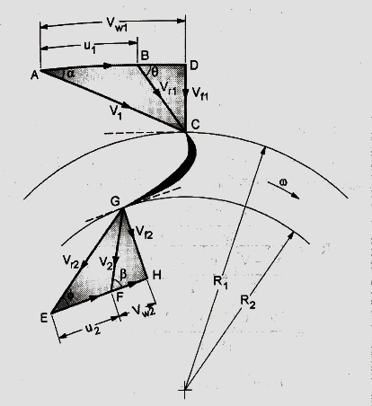
Let D1 and D2 be the outer and inner diameters of the runner rotating at N rpm.
Then, u1 = πD1N/60 and u2 = πD2 N/60.
Work Done/s, W = ρ Q (Vw1u1 ± Vw2u2) = (w/g) Q (Vw1u1 ± Vw2u2) or Runner power, P.
(1)
where, Q = discharge through the runner in m3/s
Work Done per second per unit weight of water per second,
W = (Vw1u1 ± Vw2u2) / g (1A)
In Equation (1), positive sign is taken when β is less than 90° and negative sign is taken when β is more than 90°.
Maximum work occurs when β = 90°and the absolute velocity at discharge is radial i.e. V2 is minimum and Vw2 = 0. Therefore, the equation for work reduces to:
W = ρ Q Vw1 u1 (2)
Under these conditions:
H - (V22 / 2g) = Vw1 u1 (2A)
b. Hydraulic efficiency, ηh
If H is the net head available on turbine, then Power input or water power,
Pi = ρgQH = wQH (3)
Hydraulic efficiency, ηh = Power developed by runner, P / Power input
= {ρ Q (Vw1u1 ± Vw2u2)} / ρgQH
= (Vw1u1 ± Vw2u2) / gH (4)
c. Mechanical efficiency, ηm
Mechanical efficiency, ηm = Shaft power, Ps / Power developed by runner, P
(5)
d. Overall efficiency, ηo
Overall efficiency, ηo = Shaft power, Ps / Input power, Pi (6)
Hydraulic efficiency of a radial flow inward reaction turbine ranges from 80% to 90%.
Cavitation in Reaction turbines
Only reaction turbines are subjected to cavitation. The cavitation may occur at inlet of draft tube where the pressure is considerably reduced which may be below the vapour pressure of the liquid flowing through the turbine.
The phenomenon of cavitation is defined as the formation of vapour filled bubbles of a flowing fluids in a region where the pressure of liquid falls below its vapour pressure.
Phenomenon of cavitation can be explained as follows: The vapour pressure of a liquid is the function of temperature and its height from mean sea level. In case the pressure of liquid during flow is reduced below its evaporation pressure at a given temperature, the liquid will boil and small vapour bubbles are formed. These bubbles are carried along by the fluid during flow to high pressure region where the vapours condense and the bubbles suddenly collapse. It results into formation of cavity. The surrounding liquid then rushes from all direction to fill the space thus created. These streams of liquid coming from all directions collide at the center of cavity and a very high pressure in the range of 100 to 1000 times the atmospheric pressure is generated. It generates lot of noise and vibrations and shock waves are formed. Sudden pressure generated by fluid produces hammering effect and damage to the metallic surface with which it is in contact. It causes the pitting of metallic parts called erosion.
Effects of Cavitation
The effects of cavitation are:
1. Flow pattern of fluid is modified with reduced flow rate.
2. Pitting and erosion of metal parts.
3. Collapse of cavities cause noise and vibrations of various parts.
4. Power and efficiency of turbine decreases due to cavitation.
5. Structural failure may take place due fatigue because of high rate of bubble collapse.
Methods of Preventing Cavitation
The occurrence and the resulting damage can be prevented by:
Introduction to Governing of Water Turbines
In a hydroelectric power plant, the turbine is always coupled to a generator in which the mechanical power of turbine is converted into electrical energy by the generator in the form alternating current. The power developed by various power plants is connected to a common grid which supplies power to various consumers. Various power plants are required to supply power to common grid at certain emf and frequency. Any mismatch of emf and frequency between the generator and grid may lead to serious tripping. The voltage and frequency, f of the e.m.f. generated by the alternator depends on the speed of the alternator given by the relation, f = (pN/60), where p represents the number of pair of poles and N is the speed in r.p.m. Thus, for maintaining the voltage and frequency of the generator, it is necessary to run the generator at constant speed called synchronous speed. Since the generator is coupled to the turbine, it implies that the turbine must be run at constant speed within certain fluctuations of speed permissible.
The load on the generator keeps on fluctuating while the input power to the turbine is constant. Therefore, the speed of turbine will either increase or decrease with the decrease or increase of load respectively. This leads to fluctuation of speed of the turbine. This in turn will fluctuate the speed of generator which is not desirable as discussed above. In order to run the generator at constant speed, the turbine speed is required to be maintained under variable load conditions. It is achieved by varying the discharge rate to the runner of the turbine according to the load on the turbine.
The regulation of the speed of the turbine within prescribed limits according to the load on the turbine is called the governing of turbines.
The functions of a turbine governor are:
The governing system of a turbine is based on a closed loop feedback control system. The block diagram for such a system is shown in figure below. The basic elements and their functions are as follows:
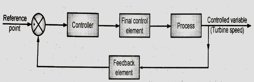
The variable which is required to be controlled is called controlled variable. In this case, the turbine speed is the controlled variable which fluctuates according to the load on the turbine.
The first step in this closed loop control system is done by measuring element called feedback element, which is speed in this case. This information is fed to the controller through the summing point or comparator. This comparator compares the present value of controlled variable with the speed at which turbine is required to run. On comparison between the present value of speed and reference point speed, if any difference between the two, an error signal is produced. The error signal is transmitted to the controller. The function of controller is to produce an output corresponding to the error and initiates an action so as to bring down the error to zero. The output of the controller is given to a final control element which is generally a heavy actuator. This actuator will actuate the mechanism to control the rate of discharge into the turbine.
Thus, it could be seen from the above discussion that the closed loop control system would function automatically in a loop till such time it reduces the error to zero and bring back the speed of the turbine to desired constant speed under all varying load conditions.
It is generally done by oil pressure governors as shown in the figure below.
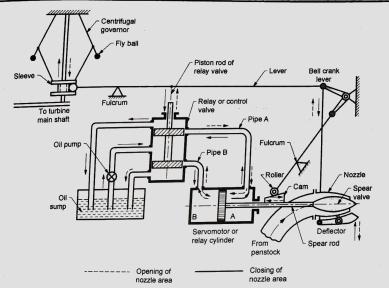
The major components of the governor mechanism are:
System uses oil in servo motor or relay cylinder since the force required to actuate the spear valve would be enormous. For this reason, the system requires an oil sump to store the oil and an oil pump to regulate the oil supply in the mechanism. Oil pump is a positive displacement type of pump like gear pump or axial piston pump. Its function is to pressurize the oil.
2. Relay or control valve
Relay valve is a spool valve having 5 ports. It is also called as control valve or distributor valve. It receives the pressurized oil from the oil pump which is diverted towards the ports connected to pipe A or pipe B. Through these pipes the oil is transferred to corresponding sides of double acting servo motor cylinder. Simultaneously, the oil will be returned from the servomotor from the opposite pipe to the sump.
3. Servo Motor or relay cylinder
It is a double acting cylinder which acts as hydraulic actuator. It receives oil from relay valve say through pipe A. The piston of the cylinder will be displaced towards left, thus forcing the oil through the pipe B into the relay valve and finally to oil sump. It will simultaneously more the spear valve to the left and increase the area of flow through the nozzle.
4. Spear valve
Spear valve controls the flow area of the nozzle. It is directly connected to the piston of relay cylinder.
5. Governor and linkages
A centrifugal governor is used as the measuring element of the closed loop control system. It is driven by the turbine shaft through bevel gears. The sleeve of the governor is connected through linkages to relay valve. The movement of sleeve is transferred through the lever to more the piston rod of relay valve.
Working
Figure above shows the position when the turbine is running at normal speed.
Consider the case when the load on the generator increases, the speed of the generator and that turbine will decrease. Since the governor is driven by the turbine shaft, its speed will also decrease. As a consequence, the flyball of the governor will move inwards due to reduced centrifugal force on the balls. As a result, the sleeve of the governor will move downwards.
The downward motion of the sleeve will be transferred to the main lever through its fulcrum. It will cause the piston rod of the relay valve to move upwards and simultaneously the bell crank lever also moves upwards. The upward motion of piston rod of control valve causes pressurized oil to flow through the pipe A to the relay cylinder and exerts a force on face A on the piston of servomotor. It moves the piston to the left, thus the spear rod with its valve will also move towards the left. It will increase the nozzle area and the rate of flow of water to the turbine increases. Therefore, the input to turbine and consequently its speed increases. During this piston movement of servo motor to the left, oil held in the cylinder towards the face B is transferred through pipe B to the oil sump via the relay valve. When the speed of turbine is adjusted to normal speed, the system would return to its original position. Opposite will be action of the whole mechanism when the load on the generator decreases. The increase in speed of turbine and generator will increase the speed of the governor. The balls flyout and the sleeve moves upwards. It causes the piston rod of relay valve to move downwards, thus opening the valve towards pipe B. Pressurized oil flows into servo motor cylinder towards the face B and causes the spear to move towards right thus closing the nozzle area. The reduced discharge to turbine runner reduces the input, hence its speed. When the speed attained by the turbine is its normal speed, the governing mechanism will return to its original position.
The basic mechanism for governing of various turbines remains the same as discussed in section above, the only difference being the method the control of discharge which varies from turbine to turbine.
In case of Pelton turbine, the discharge was controlled using the speed and spear nozzle in Francis turbine a different mechanism is used with modification in relay cylinder to control the discharge as shown in figure.
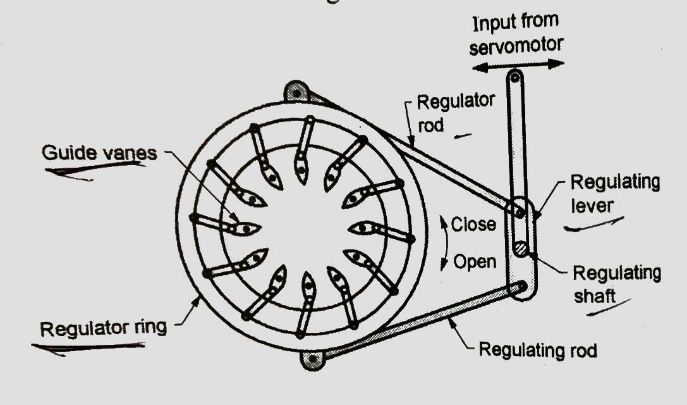
Mechanism has the following components to control the discharge.
2. Regulating rod
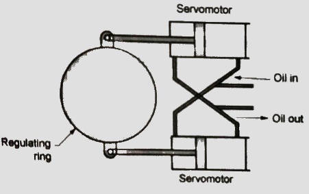
It connects the regulating ring to relay cylinder (servomotor) through the various linkages as shown in Fig. It can be seen by this mechanism; the linear motion of servomotor piston is converted into rotary motion of regulating ring. An alternate arrangement providing the rotary motion to regulating ring by using two servo motor is shown in above figure. This mechanism gives better performance since the force required for operation of Francis turbine guide vanes is much more compared to Pelton turbine.
Speed control in Kaplan turbine can also be achieved by varying the discharge by changing the guide vane angle as in case of Francis turbine with an additional feature.
However, the governing achieved by changing the guide vane angles has a serious drawback. With the change in guide vane angle, the inlet velocity triangle is changes. It results into the change in direction of absolute velocity at inlet. Hence, the direction of relative velocity at inlet is also changed, thus the water will not enter the moving blades tangential to it.
In other words, the tangential entry to runner blades can be achieved only at a particular speed of the turbine.
In order to overcome this problem, the governing of Kaplan turbine is achieved by double regulation system which controls the movement of guide vanes as well as the moving vane.
Therefore, a separate servomotor is provided to operate the runner blades which are few in numbers. The arrangement is shown in Fig.
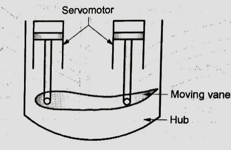
In this method, the moving blades are pivoted on the hub. It carries a pair servo motor for controlling the movement of each moving blades as shown in Fig. During the governing, the discharge is changed by changing the guide vane angles as discussed in case of Francis turbine, simultaneously the moving blade angles are also adjusted in such a way that for new position of guide vanes, the entry of water remains tangential to moving vanes over wide range of guide vane positions. Due to control of both guide and moving vanes, the Kaplan turbine gives better efficiency over wide range of loads as compared to Francis turbine.
References: -
Text Books:
1. G. T. Mase, R. E. Smelser and G. E. Mase, Continuum Mechanics for Engineers, Third Edition, CRC Press,2004.
2. Y. C. Fung, Foundations of Solid Mechanics, Prentice Hall International, 1965.
3. Lawrence. E. Malvern, Introduction to Mechanics of a Continuous Medium, Prentice Hall international, 1969.
4. Hydrantic Machine by Jagdish Lal
5. Hydraulics & Hydraulic Machines by Vasandari
6. Hydrantic Machine by RD Purohit


