UNIT 7
Rotodynamic Pumps
A pump is a device that converts the mechanical energy into hydraulic energy for fluids (liquids or gases), or sometimes slurries, by mechanical action. Pumps can be classified into different groups according to the mode of movement of the fluid. In this module we are going to focus on Rotodynamic pumps.
Definition:
Rotodynamic pumps are kinetic machines in which energy is continuously imparted to the pumped fluid by means of a rotating impeller, propeller or rotor. These pumps transfer mechanical energy to the fluid primarily by increasing the fluid kinetic energy.
Classification:
Rotodynamic Pumps can further be classified as-
In this module, we are going to look into details of centrifugal pumps mainly.
Classification of Centrifugal Pumps
- Low head pumps (up to 15m). Usually they do not have guide vanes.
- Medium head pumps (15 to 40m). These usually are provided with guide vanes.
- High head pumps (above 40m). These are multistage pumps.
2. Based on type of Casing:
Casing is designed with the motive of decreasing the loss of kinetic head to minimum.
Based on various shapes of casings, centrifugal pumps can be classified as:
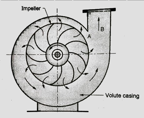
Figure shows a centrifugal pump with a volute or collecting passage round the impeller of gradually increasing area from cut water at A to delivery pipe at B. The cross-section is so designed to give a constant velocity in the volute of spiral shape. For this reason, it is also called as constant velocity volute. In such a volute casing the loss of energy is considerably reduce compared to a circular casing if employed. However, the conversion of kinetic energy into pressure energy is not possible. Due to this the efficiency of pump only increases slightly.
b. Vortex or variable velocity volute pump
An improvement of the design of volute pump shown in Figure. This pump has relatively larger overall diameter compared to pump shown in previous figure in order to provide an annular space between the impeller and volute passage.
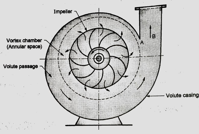
In this annular space called vortex chamber, there is a free vortex in which the velocity of flow of liquid falls as it passes into this chamber from impeller outlet to entry of volute passage. (Since in a free vortex, the velocity of whirl proportional to radial distance). Due to decrease in velocity the pressure increases radially from center outwards. The drawback of this arrangement is that to get an efficient chamber the dimensions become excessive and the pump becomes bulky and expensive. The volute pumps and vortex volute pumps are single stage pumps with horizontal shaft.
c. Diffuser or turbine pump
Figure below shows a diffuser or turbine pump which is similar to vortex volute pump, but a diffuser ring with guide vanes is fixed in annular space.
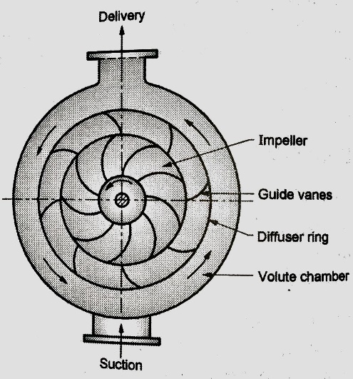
Function of guide vanes is to guide the liquid leaving the impeller in streamlined diverging passages into the volute chamber from where it flows to the delivery pipe. In case of multistage pumps, the liquid from volute chamber flows into the eye of impeller of the next stage pump and the final stage volute discharges into delivery pipe. This pump with diffuser ring becomes in fact a reversed reaction turbine and is commonly known as a turbine pump.
The guide vane passages so formed have an increasing cross-sectional area which reduces the velocity of flow; hence, the partial kinetic energy of the liquid is converted into pressure energy. Further conversion of kinetic energy into pressure energy takes place in the volute chamber of increasing cross-sectional area.
3. Based on liquid handling (Types of impeller)
Depending on the type and viscosity of liquid to be handled, a pump uses three types of impellers, accordingly the pumps are classified as follows:
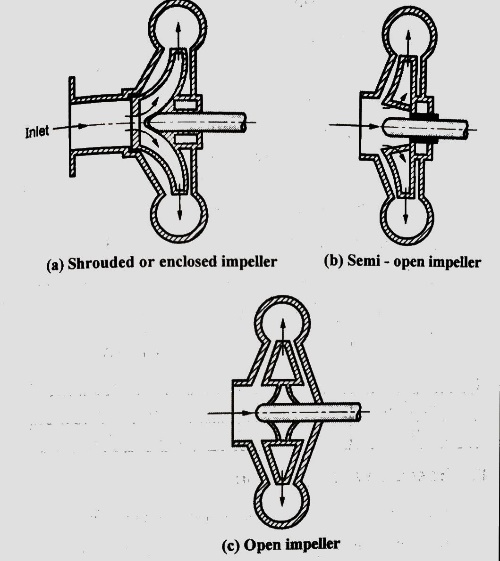
In this type of impellers, the vanes of impeller are cast between two circular discs or plates (shroud) as shown in Figure. The plate on entry side is called crown plate and the plate on back or shaft side is called base plate. This arrangement provides better guidance for liquid to flow and prevents leaking of liquid from blade tips from one passage to another passage with high efficiency. These types of impeller pumps are mostly used for clear water or for other liquids of low viscosity free from dirt.
b. Semi-open impeller
These impellers have a plate only on back side called based plate as shown in Figure. Such an arrangement helps in dealing liquids mixed with fibrous materials. Therefore, these types of impellers can be used in sewage installation, sugar and pulp industry etc. with small amount of debris.
c. Open impellers
These types of impeller do not have any cover plate on either side of the vanes. Therefore, the vanes of an open impeller are open from both sides as shown in Figure. Open impellers are not so efficient but they we useful to deal with liquids which may contain suspended solids such as sand, grit, clay etc. since these pumps do not clog.
4. Based on relative direction of flow through Impeller
Based on relative direction of flow through Impeller, the pumps are classified as:
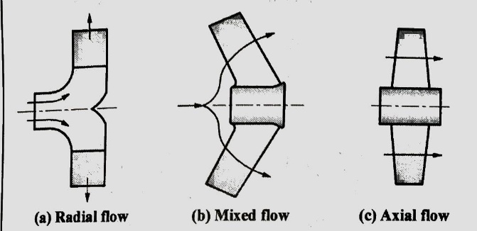
Most of the centrifugal pumps are radial flow type in which the liquid flows in the impeller in radial direction only as shown in Fig (a). In radial type of impellers, the liquid enters at the center of impeller axially and then it flows radially over impeller blades up to outer periphery. In this the pressure head is developed due to centrifugal force impressed upon the liquid.
b. Mixed flow pumps
Refer Fig (b). It is the modification of radial flow impeller in which the flow is the combination of axial and radial flow and the impeller resembles the propeller of a ship. These are also called as screw pumps due to their resemblance to shape of a screw.
The mixed flow impellers have large discharge rates of liquid compared to radial flow impellers at low heads. Therefore, these types of pumps are suitable for irrigation applications.
c. Axial flow pumps
In axial flow pumps the direction of flow of liquid through its impeller is in the axial direction only from inlet to exit as shown in Fig c. These pumps are designed for very large discharge rates at low heads; hence these are ideally suited for irrigation purposes. The pressure head developed in axial flow pump is not due to centrifugal action, rather it is due to flow of liquid on blades of aero foil section similar to generation of lift by the wings of an airplane. These pumps have adjustable blades similar to Runner blades of a Kaplan turbine.
5. Based on number of entrances to Impeller:
Centrifugal pumps based on number of entrances to the impeller can be classified as follows:
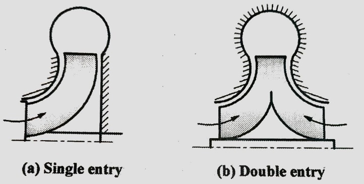
In this pump the liquid enters only from one side into the impeller from suction pipe as shown in fig a. They are also called as single suction pump.
b. Double entry or double suction pump
Refer Fig b. In these pumps entry to impeller is from both sides of impeller. In such pumps the axial thrust is negligible. It is suitable for large discharge rates.
6. Based on number of impellers per shaft:
Based on number of impellers used per shaft, the pumps are classified as:
It has one impeller and it is suitable for heads up to 40 m.
b. Multistage pump:
These pumps use two or more number of impellers in series depending upon the head requirements. In these pumps, the discharge of one pump from casing enters into the eye of impeller of the next pump in series. Total head developed by multistage pump is equal to algebraic sum of heads developed by each pump.
7. Based on shaft position:
Based on shaft position, the pumps are classified as:
Usually the centrifugal pumps are with horizontal shaft.
b. Vertical shaft pump:
These pumps are designed for specific applications and to save space. e.g. the deep well and marine pumps.
The centrifugal pump is far the most common type of dynamic pump also called as velocity pump. These are classified as rotodynamic pumps since the rotating impeller of pump impresses a centrifugal head or pressure on the liquid which leaves the impeller at a high velocity. This pressure enables the liquid to rise to a higher level. These pumps are suitable for large flow rates.
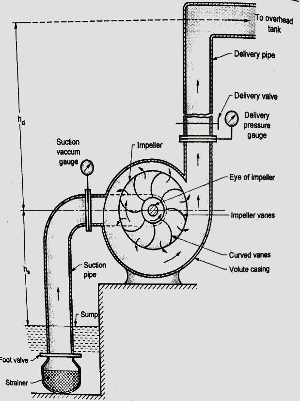
A centrifugal pump has following main components:
An impeller is a wheel or rotor having a series of backward curved vanes or blades. The impeller is mounted on a shaft which is usually coupled to a motor. The motor provides the required input energy to rotate the impeller.
2. Casing
The impeller is enclosed in a watertight casing with delivery pipe on one side and with an arrangement on suction side called eye of impeller as shown in figure. Casing has to perform two functions. Firstly, it guides the water from entry to exit of impeller. Secondly, the casing is so designed that it helps in partly converting the kinetic energy of the liquid into pressure energy.
3. Suction pipe with strainer and foot valve
The pipe which connects the sump to the eye of impeller is called suction pipe. The sump carries the liquid to be lifted by the pump. The suction pipe at its inlet is provided with a strainer and a foot valve. The function of strainer is to prevent the entry of any debris into the pump. The foot valve is a non-return valve which allows the flow of water only in upward direction. Therefore, this valve does not allow the liquid to drain out from suction pipe.
4. Delivery pipe
The pipe which connects the outlet of pump up to point it delivers the liquid to required height is called delivery pipe. A valve is provided in the delivery pipe near the outlet of the pump called delivery valve. It is a sluice type valve. Its function is to regulate the supply of liquid from the pump to delivery pipe.
Centrifugal pump works on the principle that when a certain mass of liquid is made to rotate along the impeller from the central axis of rotation, it impresses a centrifugal head. It causes the water to move radially outwards at higher velocity and causes the water to rise to a higher level. The motion of water is restricted by casing of pump, it results into pressure build up. In addition, the change in angular momentum of liquid during its flow results into increase in pressure head. The steps involved in operation of centrifugal pump are as follows:
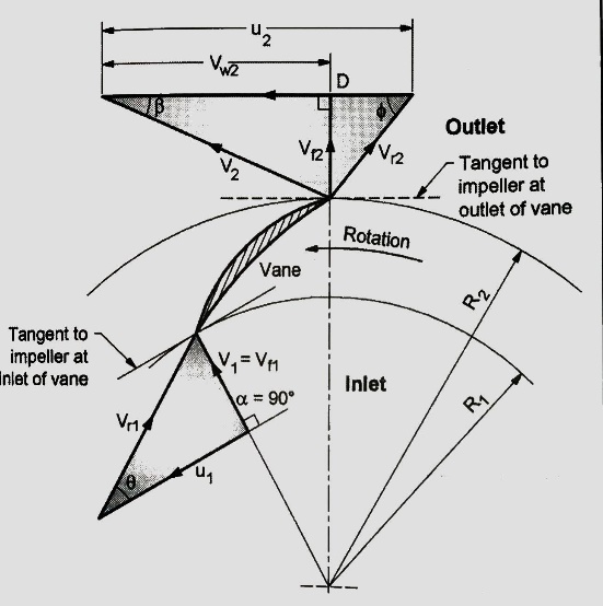
A pump is a power absorbing device in which the work is done by impeller on water. The inlet and outlet velocity diagrams are shown in figure. They can be drawn similarly as those for inward flow reaction turbine. in pumps, the water enters the impeller at its center and leaves at its outer periphery.
Following assumptions are made:
Let, D1 = Diameter of impeller at inlet = 2 x Radius, R1
D2 = Diameter of impeller outlet = 2 x Radius, R2
N = Speed of impeller in rpm.
The tangential blade velocity at inlet, u1 and at outlet u2 can be written as
U1 = ω R1 = (2πN / 60) R1
U2 = ω R2 = (2πN / 60) R2
V = Absolute velocity
Vr = Relative velocity
Vf = Velocity of flow
Vw = Velocity of whirl
Suffix 1 and suffix 2 represent the velocity at inlet and outlet respectively.
Also, α = Angle made by absolute velocity V1 at inlet
Θ = Inlet angle of vane
Φ = Outlet angle of vane
And β = discharge angle of absolute velocity at outlet.
Work Done (WD) by impeller on water per N weight of liquid per second is given as,
WD = (1 / g) (Vw2 u2 - Vw1 u1) (1)
The above equation is called as Euler’s momentum equation for centrifugal pump.
But Vw1 = 0, since the entry is radial.
∴ WD = Vw2 u2 / g (2)
In case working liquid is water and the weight of water is w, then the work done on water per second becomes,
W-D/s = w x Vw2 u2 / g = ρ.Q. Vw2 u2 (Nm/s) (3)
where, Weight of water/s,
w = ρ.g.Q (4)
Discharge rate,
Q = Area x Velocity of flow
Q = π D1 B1 Vf1 = π D2 B2 Vf2 (5)
Where, B1 and B2 is width of impeller at inlet and outlet respectively.
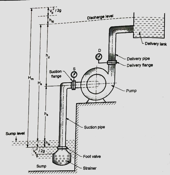
Various heads
Various heads connected with centrifugal pump installation are shown in Fig.
Pressure head, H in meter of fluid column is given by the equation,
p= ρ.g.H (N/m) (i)
Let, Vs = Velocity of liquid in suction pipe, m/s
Vd = Velocity of liquid in delivery pipe, m/s
hfs = Loss of head due to friction in suction pipe, m
hfd = Loss of head due to friction in delivery pipe, m
Definitions connected with various types of head are as follows:
It represents the vertical distance between the top surface level of sump and the center of impeller.
2. Delivery lift, hd
It represents the vertical distance between the center of impeller and the discharge level in delivery tank.
3. Static head, Hs
It is the sum of suction lift, hs and delivery lift, hd. i.e. it represents the vertical distance between the top surface level of sump to discharge level in delivery tank. Hence static head,
Hs = Suction lift, hs + Delivery lift, hd (1)
4. Gross head, Hg
The pump is required to work against the static head and the other losses like friction losses in pipes and head corresponding to kinetic energy due to suction and delivery velocity of liquid. The total head against which the pump has to work is called the gross head, Hg.
Hg = Hs + hfs + hfd + (Vs2 / 2g) + (Vd2 / 2g) (2)
5. Manometric head, Hm
The manometric head is defined as the minimum amount of head against which the pump has to work to deliver the required discharge. It is required to operate against the following heads:
∴ Manometric head Hm = Static head, Hs + Friction losses, (hfs + hfd) + Velocity head at discharge, (Vd2/2g). (3)
Various efficiencies
Various efficiencies related to centrifugal pumps are as follows:
The ratio of power available at the impeller or power delivered by impeller to liquid to the power input at the shaft (motor power or shaft power) is known as mechanical efficiency.
∴ ηm = Power available at impeller, P(kW) / Shaft power, Ps (kW)
But, power available at impeller is given as, P = ρ (Q+q) Vw2 u2
ηm = {ρ (Q+q) Vw2 u2} / Ps = (Ps - Pmech losses) / Ps
where, q = leakage loss
2. Manometric efficiency, ηmano
It is defined as the ratio of manometric head, Hm developed by the pump to the head imparted by the impeller to liquid. Mathematically,
∴ ηmano = Manometric head, Hm / Head imparted by impeller (Vw2 u2 / g)
∴ ηmano = (g Hm) / Vw2 u2
3. Volumetric efficiency, ηv
It is ratio of actual liquid discharged from the pump in m3/s to the theoretical liquid passing through the impeller in m3/s.
Mathematically, ηv = Actual discharge, Q / Theoretical flow through impeller, (Q+ q)
where, q represents the loss of discharge due to leakage loss.
4. Overall efficiency, ηo
It is defined as the ratio of power output of the pump called water power to the shaft power.
Thus, ηo = Power output / Shaft Power, Ps
ηo = ρ g Q Hm / Ps
Rate of energy transfer per unit mass by the impeller is called Euler’s head, He.
He = Vw2 u2 / g (i)
From outlet velocity triangle, Vw2 = u2 - Vf2 cot Φ
But, Vf2 = Q / A2
∴ Vw2 = u2 - (Q / A2) cot Φ
Putting in (i), we get, He = {u2 - (Q / A2) cot Φ} x u2 / g (1)
At a given speed, u2 is constant and so is the exit area A2 of impeller and discharge angle Φ. Therefore, Equation (1) can be written in the form,
He = K- K1 Q
where, K and K1 are constants as K = u22 / g & K1 = u2 cot Φ / gA2
Various vane shapes in centrifugal pumps:
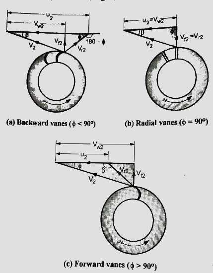
In these vanes, the outlet tip of vane is curved in the direction opposite to motion of impeller as shown in Fig a. Therefore, angle Φ becomes less than 90°.
2. Radial Vanes (Φ = 90°)
3. Forward Vanes (Φ > 90°)
The outlet tip angle of vane is in the direction of motion of impeller and it makes an obtuse angle with the tangent to the rotor. These three types of vanes with outlet velocity diagram are shown in Fig.
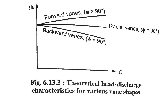
From Equation (1) it is evident that
The Euler's head, He will keep on decreasing with the increase in discharge rate Q. Therefore, the energy transfer with backward vanes is reduced.
b. For radial vanes (Φ = 90°), cot Φ = 0, therefore, the Euler's head remains constant irrespective of discharge rates.
c. In case of forward vanes (Φ > 90) the Euler's head keeps on increasing with increase in discharge rates. However, the absolute velocity V2 at exit of impeller is also increased. The conversion of this kinetic energy (V22 / 2g) into pressure energy cannot be carried out very effectively in diffuser section of pump since the liquid has a tendency to break away from the walls of the diverging passages. However, in case the diffusion process is too rapid in a small diffuser section, the liquid may reverse direction of flow due to resultant high-pressure gradient. It causes formation of eddies and loss of energy.
d. For the reasons discussed above, the pumps are usually designed with backward vanes in the range of Φ = 20° to 35° except in cases where the impeller diameter and high head is the major consideration.
The theoretical head-discharge characteristic curves based on above discussion is shown in next diagram. These curves are straight lines since,
He = K - K1 Q
Since power required by impeller,
P = ρ g Q He,
It follows, P = ρ g Q (K - K1 Q)
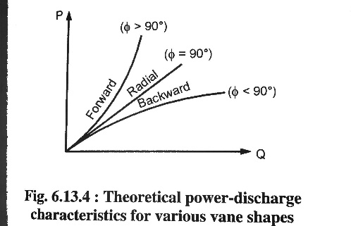
The power variation with variation in discharge Q for forward, radial and backward vanes is shown in Fig. 6.13.4. It could be seen that with forward vanes, the input power required increases very rapidly with increase in discharge rates.
When pump is started, it will not deliver any liquid until the pressure difference in impeller is large enough to overcome the manometric head. The pressure head developed is due to centrifugal head caused by the centrifugal force impressed on rotating liquid.
But, Centrifugal head = (u22 - u12) / 2g
The flow will only commence when the centrifugal head exceeds the manometric head, Hm.
Therefore,
(u22 - u12) / 2g ≥ Hm (1)
(πD2N/60)2 - (πD1N/60)2 ≥ 2g Hm
∴ For minimum speed,
N = (60/π) x {√(2g Hm)} / {√ (D22 - D12) } (2)
Equation (2) gives the minimum speed required for pump to start discharging the liquid.
The centrifugal pumps with two or more number of identical impellers are called multistage centrifugal pumps.
The impellers of these pumps may be attached on the same or on different shafts. The multistage pumps are needed either to increase the head or the discharge compared to a single stage pump, accordingly the impellers are connected in series or parallel as follows:
Two or more identical impellers are connected in series to generate high heads with constant discharge. The arrangement of multistage pump with two impellers in series is shown in Fig. 6.14.1. The water from suction pipe is supplied to impeller - 1 where its head is raised. The discharge from impeller 1 is guided through the guided passages into the inlet of impeller- 2 where its pressure is further increased. If there are a greater number of impellers in series the similar operations are conducted and finally the last impeller in series discharge the water.
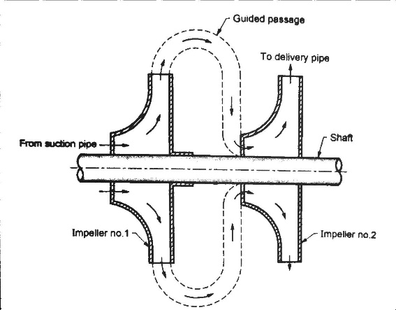
Let, n = number of impellers
Hm = head developed by each impeller
Total head developed, H = n Hm (1)
Total discharge passing through each impeller remains the same.
Therefore, Qtotal = Q (2)
These pumps are used where high heads are needed at relatively low discharge as in boiler practice.
Advantages of multistage pumps in series compared to single stage pump are:
2. Multistage Centrifugal Pumps for High Discharge Two or more identical impellers are connected in parallel to generate high discharge at constant heads. The arrangement of multistage pumps in parallel are shown in figure. Each pump works as a separate unit and lifts the water from the sump by their respective suction pipes and their delivery pipes are connected to common delivery pipe. Each pump develops the same head and discharge of pumps are added.
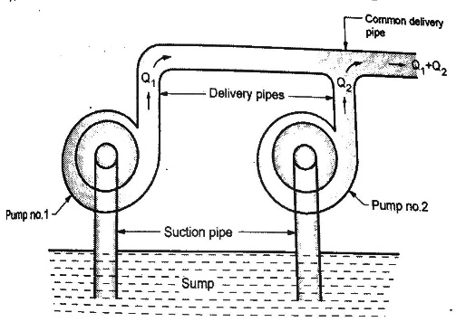
Therefore, Total head, HTotal = Head developed by each impeller, Hm
Total discharge, QTotal = Number of pumps x Q
Where, Q is the discharge of each centrifugal pump.
A centrifugal pump is designed to develop certain manometric head and discharge at constant speed since the pumps are usually driven by A.C. motors. In certain cases, the pumps may be driven by an I.C. engine at variable speed or the pump in actual practice may needed to develop a certain head or discharge. Under these actual conditions, the behaviour of the pump will be different than expected. Therefore, various tests on the pump under variable conditions are conducted in order to predict the behaviour and performance of the pump. The test results are then plotted on a graph under different flow rates, head and speed.
The curves thus obtained are known as characteristic curves for the pump.
Types of Performance Characteristic Curves
The performance characteristic curves are broadly divided into following four categories:
1. Main characteristic curves.
2. Operating characteristic curves.
3. Iso-efficiency or Muschel curves.
4. Constant head and constant discharge curves.
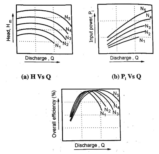
Main characteristic curves are obtained by test run at constant speed and the discharge is varied by means of delivery valve.
At each discharge, the manometric head Hm and input power P are measured and the overall efficiency ηo is calculated. Test curves are plotted between Hm vs Q, P vs Q and ηo Vs Q as shown in figure for that constant speed. The test run is repeated by running the pump at another constant speed. A family of curves will be obtained a various constant speed N1, N2 .... as shown in Fig.
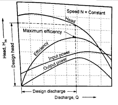
2. Operating characteristic curves.
The pumps are designed for maximum, efficiency at a given speed called designed speed. Therefore, the pumps are test run at designed speed as provided by the manufacturer of the pump. The discharge is varied as discussed in case of main characteristic curve and the head and power input are measured. The overall efficiency of the pump is calculated. The performance curve thus obtained at design speed are called operating characteristic curve at shown in figure.
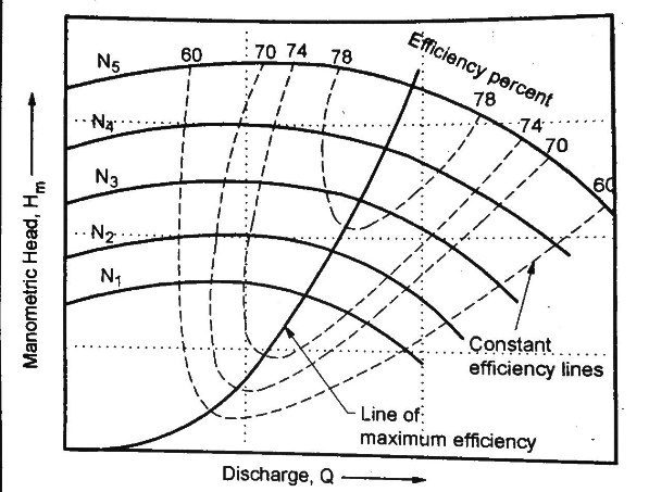
3. Iso-efficiency or Muschel curves.
Iso-efficiency i.e. constant efficiency curves are useful in predicting the performance on entire operations and its best performance.
These characteristic curves can be drawn with the help of ηo Vs Q and Hm vs Q curves shown in figure in previous part. The method is as follows:
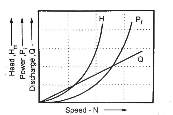
4. Constant head and constant discharge curves.
Pumps do not always operate at designed speed and conditions. So, it is necessary to compute performance of pump under various conditions to predict the performance. For these curves, delivery valve opening is fixed and kept constant during the test on pump. Then it is operated at variable speed and characteristics are plotted as shown below.
The following table summarizes the capabilities of centrifugal and positive displacement pumps.
Property | Centrifugal | Positive Displacement |
Effective viscosity range | Efficiency decreases with increasing viscosity (max. 200 centipoise) | Efficiency increases with increasing viscosity |
Pressure tolerance | Flow varies with changing pressure | Flow insensitive to changing pressure |
Efficiency decreases at both higher and lower pressures | Efficiency increases with increasing pressure | |
Priming | Required | Not required |
Flow (at constant pressure) | Constant | Pulsing |
Shearing (separation of emulsions, slurries, biological fluids, food stuffs) | High speed motor damages shear-sensitive mediums | Low internal velocity. Ideal for pumping shear sensitive fluids |


