Unit 1
Introduction
A mechanism is defined as the assembly of bodies in such a way that motion in one body causes constrained and predictable motion in other bodies. Or we can say a mechanism is a combination of several bodies to produce a specified motion Mechanisms can be classified in following four types:
Classification of Mechanisms
The mechanisms are of the following types:
1. On the basis of number of links
a. Simple mechanism: A mechanism which has four links.
b. Compound mechanism: A mechanism which has more than four links.
2. On the basis of number of pairs
a. Mechanism having three pairs.
b. Mechanism having 4 pairs.
c. Mechanism having more than 4 pairs.
3. On the basis of motion of particles
a. Planar mechanism: When all the links of the mechanism lie in the same plane.
b. Spatial mechanism: When the links of the mechanism lie in different planes.
Kinematics
Kinematics is the branch of mechanics in which the motion of a particle is studied without consideration of forces. Kinematics of machines deals with the study of the relative motion of machine parts. It involves the study of position, displacement, velocity and acceleration of machine parts.
Kinematic link (or) element
Kinematic link or element is the basic or smallest unit of a mechanism. Generally kinematic links are assumed to be rigid during analysis of kinematic performance of a machine. These links can be classified in following two categories:
Based on number of elements of link | Based on type of structural behavior |
Binary link: Link which is connected to other links at two points.
| Rigid link. A rigid link is the one which does not deform during the transmission of the motion. e.g. connecting rod, crank etc. |
Ternary link: Link which is connected to other links at three points.
| Flexible link. A flexible link can deform partly during transmission of motion without affecting the transmission. e.g.-belts, ropes, chains and wires. |
Quaternary link: Link which is connected to other links at four points.
| Fluid link. A link in which transmission of motion takes place through the fluid pressure. e.g.- hydraulic presses, jacks and brakes. |
Kinematic pair
Connection between two links is known as a kinematic pair when the relative motion between them is a constrained motion.
Classification of kinematic pair
The kinematic pairs may be classified according to the following considerations:
i.Based on relative motion between pairing elements:
Name of kinematic pair | Description | Diagram |
Siding pair | Two elements so connected that one element slides over or inside the other. DOF =1 |
|
Turning/Revolute pair | Connection between two elements in such a way that one element rotates with respect to another. DOF =1 |
|
Cylindrical pair | Relative motion between the pairing elements is the combination of turning and sliding, DOF =2 |
|
Rolling pair
| Contact between the pair elements is rolling. DOF = 1 |
|
Spherical pair |
When one element in the form of a sphere turns about the other fixed element, it forms a spherical pair. DOF = 3 |
|
Helical/screw pair | In this kind of pair one element turns about the other element through the screw threads present in it. DOF = 1 |
|
ii. Based on nature of contact between elements:
Name of kinematic pair | Description | Diagram |
Lower pair | If the joint by which two members are connected has surface contact, the pair is known as a lower pair. |
|
Higher pair | If the contact between the pairing elements takes place at a point or along a line, it is known as a higher pair. |
|
iii. Based on the nature of mechanical constraint:
Name of kinematic pair | Description | Diagram |
Closed pair | Elements of pairs held together mechanically due to their geometry constitute a closed pair. |
|
Unclosed/force closed pair | Elements of pairs held together by the action of external forces constitute unclosed or force closed pairs. |
|
Degrees of freedom/mobility of a mechanism:
Degrees of freedom of a kinematic pair is defined as the number of independent relative motions, both translational and rotational, a kinematic pair can have.
Degrees of freedom = 6- number of restraints
Kutzbach criterion:
The Kutzbach criterion for determining the number of degrees of freedom of a planar mechanism is:
F=3n-1-2p-h
Where, F = number of degree of freedom for mechanism
n = number of links
p = number of joints having single degree of freedom
h = number of joints with 2 degrees of freedom.
Kinematic chain
A kinematic chain may be defined as an assembly of links in which the relative motion of the links is possible and the motion of each relative to the others is definite. The last link of the kinematic chain is attached to the first link. e.g. Four bar chain and slider crank mechanism.
The Four Bar Chain Mechanism
It is the most fundamental mechanism, which consists of four binary links interconnected by four pin joints in the form of a quadrilateral. In a four-bar chain mechanism link that makes complete revolutions is the crank, the link opposite to the fixed link is the coupler, and the fourth link a lever or rocker, if it oscillates or another crank, if it rotates shown in Figure 1.
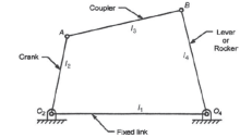
Figure 1. Four bar chain mechanism and its components
This law states that a four-bar chain mechanism has at least one revolving pair if the sum of length of smallest and largest links is less than sum of length of other two links.
(l+s)≤(p+q)
Where, l = length of largest link
s = length of smallest link
p and q = lengths of other two links.
Mechanisms that follow the above criteria are also known as class I mechanism. If (l+s)>(p+q) The mechanism is known as class II mechanism. In which every inversion of a four-bar chain results in a rocker-rocker mechanism.
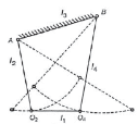
Kinematic inversion is the different kinds of mechanisms by fixing different links of a mechanism. Kinematic inversions of four-bar chain mechanism are:
1. Double crank mechanism
If the smallest link of the four bar chain is fixed the resulting mechanism is a double crank mechanism. In this mechanism both input and output links make complete revolution.
2. Crank-rocker mechanism
If any link adjacent to the smallest link is fixed, a crank-rocker mechanism is obtained. In this mechanism one link makes complete revolution while one link oscillates.
3. Double crank mechanism
This inversion of a four-bar chain mechanism is obtained when the link opposite to the smallest link is fixed. In this case both input and output links oscillate.
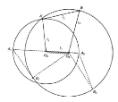
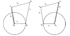
(a) (b) (c)
Figure 2. Inversions of four-bar chain mechanism (a) double crank (b) crank-rocker mechanism (c) double rocker mechanism.
Some practical applications of four bar chain mechanism
Inversion | Application | Diagram |
Double crank | Locomotive wheel |
|
Crank rocker | Beam engine |
|
Double rocker | Watt indicator |
|
Slider-crank mechanism
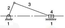
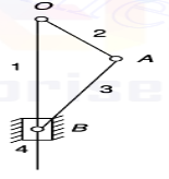
When one of the turning pairs of a four-bar chain is replaced by a sliding pair, it becomes a single slider-crank chain mechanism. In Figure 3 links 1-2, 2-3 and 3-4 form turning pairs while links 4-1 form a sliding pair.
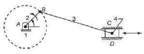
Figure 3. Slider crank mechanism
Inversions of slider crank chain
Slider crank mechanism has following four inversions:
Inversion | Description and Application | Diagram |
First inversion | Link 1 is Fixed. Link 2 and 4 are crank and slider. Application: Reciprocating engine and reciprocating pump etc. |
|
Second inversion | If we fix the crank of the previous mechanism, link 1 and 3 can complete the revolution and slider slides on link 1. Application: Whitworth quick-return mechanism and Rotary engine. |
|
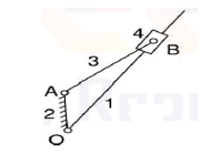
Third inversion | This inversion is obtained by fixing the 3rd link, in this case link 2 rotates while link 4 oscillates. Application: Oscillating cylinder engine and crank and slotted lever mechanism. |
|
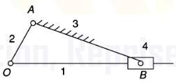
Fourth inversion | If we fix the 4th link of the slider crank mechanism, link 3 and the end A of link 2 start oscillating about pivot B on link 4 and the end O reciprocates along the axis of the fixed link. Application: Hand pump. |
|
Reference Books
1. Thomas Bevan, Theory of Machines, 3rd edition, CBS Publishers & Distributors, 2005.
2. CleghornW.L. , Mechanisms of Machines, Oxford University Press, 2005.
3. Robert L. Norton, Kinematics and Dynamics of Machinery, Tata McGraw Hill, 2009.
4. Ghosh A. and Mallick A.K., Theory of Mechanisms and Machines, Affiliated East West Pvt. Ltd, New Delhi, 1988.


