Unit 2
Kinematic analysis of plane mechanism
Kinematics analysis of a mechanism involves the study of relative motion of different parts of a mechanism and machine without considering the forces on it. In this chapter we are going to discuss about the displacement, velocity and acceleration of a mechanism.
Displacement of a particle or a body can be defined as the change in position with respect to a given reference. It can be of two types:
Linear displacement: linear displacement is the change in position in linear direction. Represented by symbol s.
Angular displacement: it is the angle subtended by a body at the center in radians when it is moving in circular path. It is denoted by .
Velocity can be defined as the rate at which a body changes its position with respect to time. Velocity is a vector quantity. Just like displacement velocity is of two types:
Linear velocity: linear velocity can be defined as the rate of change of position with respect to time by a body when it moves in a straight-line path. Its unit is m/sec.
Angular velocity: angular velocity can be defined as the rate of change of position with respect to time when it moves in the circular path. Its unit is rad/sec. The relationship between linear and angular velocity is given by equation below:

Here v is the linear velocity, while is the angular velocity and r is the radius of circular path in which the body is moving.
Relative velocity: Relative velocity can be defined as the comparative velocity of two moving bodies with different or same velocity. Let us assume the va and vb be the velocity of body A and B respectively. Relative velocity of body A with respect to the body B is given by:

Similarly, relative velocity of body b with respect to body a is given by:

Motion of a Link:
Let us assume that we have a link AB shown in figure 1. A and B be the end points of the given link and the end B is rotating in clockwise direction with respect to A. In this situation the distance between these end points remains unchanged and there is no relative motion between the points A and B along the line joining them. But in this case point B is having relative motion in the direction perpendicular to link AB.
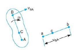
Figure.1. Motion of a link
From above discussion we can say that relative velocity of two points on a link is always perpendicular to the line joining those two points.
Hence in order to represent the relative velocity of B with respect to A in the above link we use a vector which is perpendicular to the link.
The velocity of point B with respect to point a is given by:

Similarly, the velocity of point C with respect to point A is given by

From above equation we can conclude that the point c on vector ab divides it in the same ration as C divides the link AB which is shown below.

Velocity of a link can be obtained by following two ways
Relative velocity method
Let us consider a four-link mechanism shown in figure 2, in which link AB is be the driver which is rotating with an angular velocity , link AD is fixed, link BC be the coupler and the link CD be the driven or output link, whose velocity can be obtained as follows:

As the link AD is fixed so in order to obtain the absolute velocity of any point on the mechanism can be obtained relative to any point on the link AD. That’s why the velocity of C relative to A is equal to velocity of C relative to D
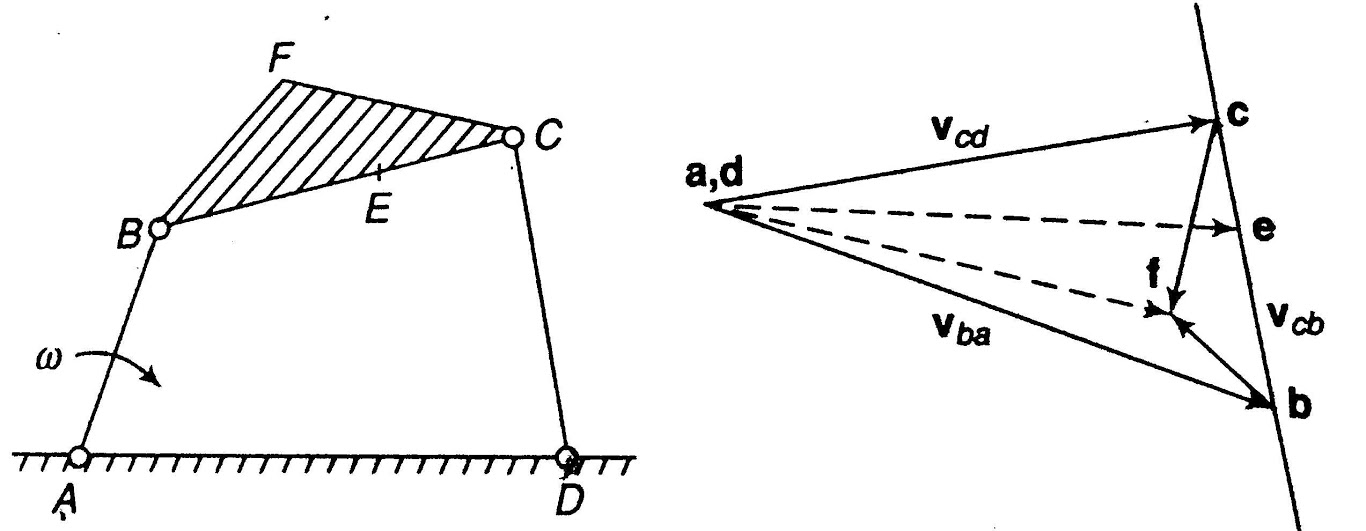
Figure 2. Four bar mechanism and its velocity diagram

From the velocity diagram

Where 


In order to obtain the unknown velocities velocity diagram with a given scale is to be made. Steps to draw the velocity diagram are as follows:


Velocity of intermediate points
The velocity of any intermediate point can be obtained by dividing the velocity vector in the ratio same as the point divides the link. velocity of point E relative to B on the link BC is represented by be and can be obtained as follows:

Velocity of offset points
In figure 2, point F be the offset point on the link BCF. In order to obtain the velocity of point F, construct a line perpendicular to link BC through point b in velocity diagram and another line perpendicular to BC through point c. the intersection point of these two perpendicular lines will provide the point f, as shown in figure 2. By joining the point f and a/d we can obtain the absolute velocity of the offset point f, which is represented by the vector af or df.
Vector equation for the point F is given as follows:


Angular Velocity of Links
From the figure 2 we can see that the point C moves in upward direction relative to point B and it is represented by the vector bc in the velocity diagram. Hence, we can say that moves in counter-clockwise direction with respect to B.


Similarly, if we see the motion of point B relative to point C, the point B moves down ward direction with respect to point C shown by vector cb in velocity diagram. But the sense of rotation of point B relative to C is again counter-clockwise direction.
Therefore, the angular velocity of a link about one extremity is same as the angular velocity about the other.
Velocity of Rubbing
Figure 3 shows the ends of two links of a turning pair, which consists of two parts one is pin and other is hole. During operation hole of one link will rub on the surface of pin of the other link. Such relative motion between the pin surface and the hole is known as rubbing velocity, it can be calculated by the obtaining the algebraic some of angular velocities of the connecting links multiplied by the radius of pin.

Figure.3. Ends of two links of a turning pair
Consider a turning pair shown in figure 4, in which link OA and OB are connected by a pin joint having angular velocity 1 and 2 respectively and r be the radius of pin. The rubbing velocity of the pin joint is given by

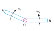
Figure.4. Turning pair connected by pin joint
If the links are rotating in same direction, rubbing velocity is given by:

In case when the pin joint connects a sliding member to a turning member, angular velocity of sliding link is taken as 0. Let us assume in such pair be the angular velocity of the turning link and r be the radius of pin, then

Consider figure 5 in which the link OA is the crank which is rotating with an angular velocity of rad/sec, link B is sliding on the fixed guide G and Ab be the coupler link. if we have to find the velocity of the slider, we can follow the given steps
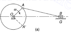
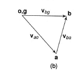
Figure.5. (a) Slider crank mechanism (b) velocity diagram of slider crank mechanism
Step 1: Draw the velocity diagram see figure 5(b).
To draw the vector diagram first of all, draw a vector oa (denoted by vao) perpendicular to the link OA with a suitable scale.
Link OG is fixed hence the vector og is a point vector without any length.
Now draw a line perpendicular to link AB and another line representing the motion of slider in horizontal direction from point og.
Intersection of the line perpendicular to the link AB and horizontal line representing the motion of slider gives the point b.
Now we get the vectors bg (denoted by vbg) and ab (denoted by vba) the length of these vectors represents the velocities of link AB and the slider at B.
Step 2: Write the vector equation for the velocity


From figure 5(b)


Step 3: Now convert the obtained vectors using the scale selected for drawing velocity diagram.
bg represents the velocity of B relative to O.
ao represents the velocity of A relative to O.
ab represents the velocity of A relative to B.
Angular velocity of coupler link can be obtained by:

Example 1. In the mechanism shown in Figure the piston D moves in the vertical direction upwards with a velocity of 5 m/s.
O1A = 7.5 cm, O1O2 = 30 cm, AB=25 cm, O2C = O2B = 10 cm, CD = 25 cm, and BC =12.5 cm.
Find the speed in rpm and direction of rotation of crank O1A.
Solution:
Draw the configuration diagram with a given suitable scale e.g. in this case scale is taken as 1cm = 5cm shown in figure a.
Now let us assume that link O1A is rotating in clockwise direction and the velocity of point a i.e. va is plotted as 5cm on a scale.
Now draw the velocity diagram Shown in figure b as follows:
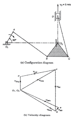
1. Draw va= o a ⊥ O1A, o1a = 5cm.
2. Draw ab ⊥ AB and o2b ⊥O2B meeting at point b.
3. Draw bc ⊥ BC and o2c ⊥ O2C meeting at point c.
4. Draw o2d ⊥ O2D and cd ∥ CD meeting at point d.
Now by measurement
o2d = 2 cm represents the vd which is equal to 5m/s.
for our scale 1 cm = 2.5 m/s.
And va =2.5×5= 12.5 m/s.


Instantaneous Center Method
Instantaneous center can be defined as a point about which link can be considered to be rotating at a given instant. Such a center has zero velocity, i.e. the link is at rest at this point. This center varies from instant to instant for different positions of the link. The locus of these centers is termed the centrode. Number of instantaneous centers for a mechanism can be calculated as follows:

Where N is the number of instantaneous centers and n be the number of links in the mechanism.
Properties of Instantaneous Center
Types of Instantaneous Centers
There are three types of instantaneous centers for any mechanism. Figure 6 illustrates all the types of instantaneous centers, in which the instantaneous centers 12 and 14 does not move from its position because one link among the two links for the given instantaneous center is fixed, hence these instantaneous centers are termed as the fixed instantaneous centers.
Instantaneous centers 23 and 34 always remains at the at the intersection of the given links hence they may change their position as the links moves but their position on the links is permanent hence, these instantaneous centers are known as permanent instantaneous centers.
Instantaneous centers 13 and 24 changes their position in space with the configuration of mechanism and they also does not lie on any permanent position on the links, hence they are neither permanent nor fixed.
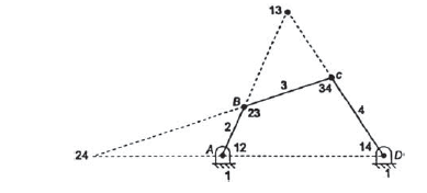
Figure.6. Instanteneous centers of four bar mechanism
Location Instantaneous Centers
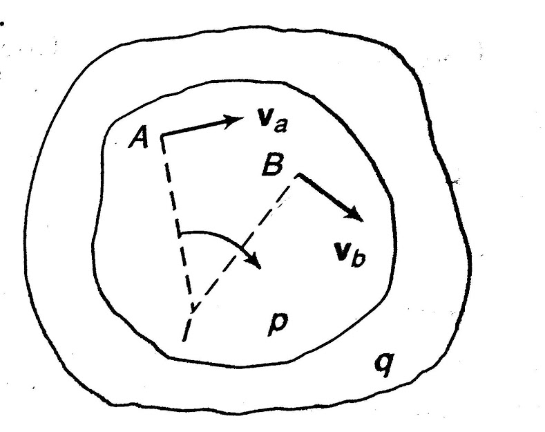
According to the definition instantaneous center is the point where the relative velocity of the two points on a body is zero. Hence, in order to locate instantaneous center, we draw perpendicular at these points from the direction of their motion and the intersection point of these lines gives the instantaneous center as shown in figure 7(a). To locate instantaneous centers for a mechanism following observation are helpful:
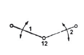
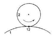
(a) (b) (c)
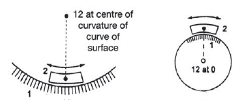
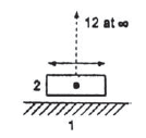
(d) (e) (f)
Figure.7. Location of instantaneous center for various cases
Arnold–Kennedy Theorem
According this theorem instantaneous centers of three -plane bodies in relative motion to each other must be co-linear.
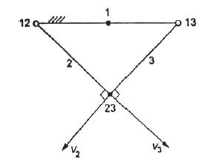
Let us consider three links 1,2 and 3 as shown in figure 8. In the given diagram link 1 is fixed while links 2 and 3 are movable. Instantaneous center of link 1,2 and 1,3 lies on the pin joint at 12 and 13 as shown in figure 8. Now let us consider the instantaneous center for the link 2 and 3 in not co-linear to 12 and 13. In this case point 23 have two different direction of motion which is not possible. The one direction of motion for the point 23 is possible only if it is colinear to 12 and 13. That is what Kennedy’s theorem says.
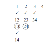
Figure.8. Proving Kennedy theorem
Method to Locate Instantaneous Centers
To locate instantaneous center for a mechanism we have to follow following steps:
Step 1: Determination of number of instantaneous centers N by using relation discussed above. Let us consider the number of links for the given mechanism is 4 shown in figure 9.
Therefore,

Step 2: Make a list of all the instantaneous centers as follows:
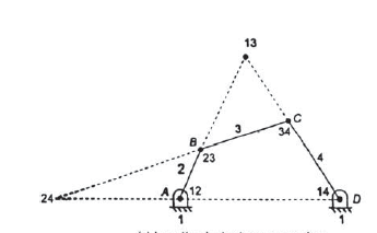
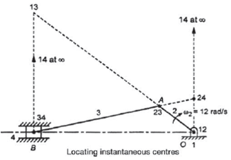
Figure.9. Instantaneous centers for a four-bar mechanism
Step 3: Locate the fixed and permanent instantaneous centers using tick mark by inspection.
Step 4: Now to locate neither fixed nor permanent instantaneous centers use Kennedy’s theorem.
Now apply Kennedy’s theorem here links 1,2 and 3 are in relative motion hence the instantaneous center 13 can be obtained by joining the lines extending the obtained by joining instantaneous centers 12, 23 and 14, 34. Similarly links 1,2 and 4 are in relative motion and the instantaneous center 24 can be obtained at the intersection of the lines joining the instantaneous centers 23,34 and 12,14.
Determination of Angular Velocity of a Link
The angular velocities of two links vary inversely as the distances from their common instantaneous center to their respective centers of rotation relative to the frame. For example, for the four-bar mechanism shown in Fig.9. if 2 is the angular velocity of link 2, then angular velocity 4 of link 4 will be given by the following relationship:

If the respective centers of rotation are on the same side of the common instantaneous center, then the direction of angular velocities will be same. However, if the respective centers of rotation are on opposite sides, then the direction of angular velocities will be opposite.

Example 2. Locate the instantaneous centers of the slider crank mechanism shown in figure. Find the velocity of the slider.
OA = 160 mm, AB = 470 mm, and OB = 600 mm, 2 = 12 rad/s cw.
Solution.
Given n=4, 2 = 12 rad/s cw.
Number of instantaneous centers,

Make a list of all the instantaneous centers as follows:
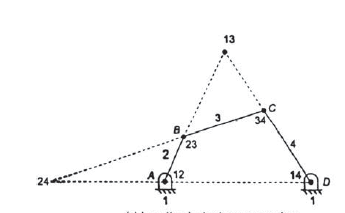
we have
Center 13: at the intersection of line joining 12, 23 and 14, 34.
Center 24: at the intersection of line joining 12, 14 and 23, 34.
5. By measurements, we have
13-23 = 550 cm
13-34 = 390 cm


Now velocity of slider

Acceleration of a Body
Acceleration of a body can be defined as the rate of change of velocity with respect to time. Similar to velocity it can be of two types:
Acceleration of a link
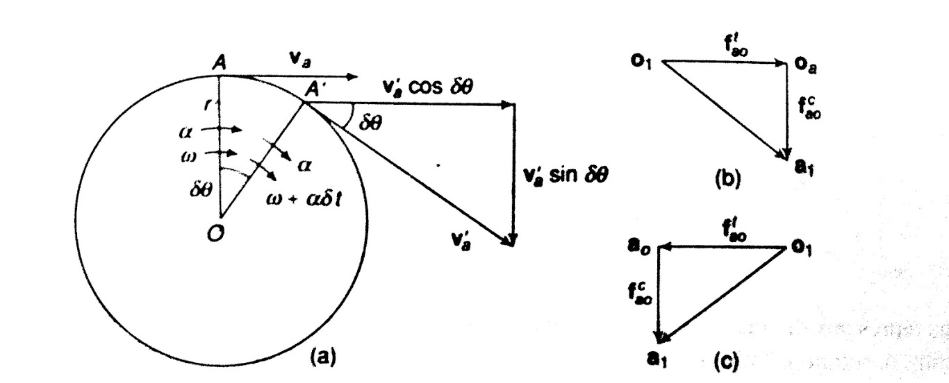
let us assume a link OA of length r rotating in clockwise direction having angular velocity at the given instant and the angular acceleration in the direction of the angular velocity shown in figure 10.
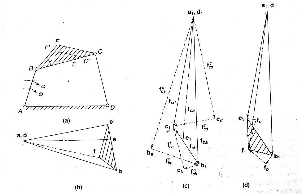
Figure 10. components of angular acceleration of a rotating link.
In the figure 10 (b) shows the acceleration diagram of the link OA when the acceleration supports the velocity while figure 10 (c) shows the acceleration diagram when acceleration opposes the velocity.


Total acceleration of the link OA is given by the vector sum of tangential and centripetal acceleration i.e.

And the direction is given by

Acceleration of a four-link mechanism
Let us consider the figure 11 which shows the four-link mechanism, it’s velocity and acceleration diagrams. In the given mechanism link AB is rotating with an angular velocity , in clockwise direction with angular acceleration supporting the angular velocity.
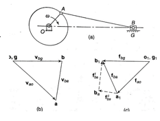
Figure.11. Acceleration analysis of four-link mechanism
Now in order to find the acceleration of various points on the mechanism we have to follow given steps.
Step 1: Write the vector equation of acceleration for the given point.
e.g.

i.e. 
Or 

Now each of the above three accelerations have two components i.e. tangential and centripetal. So,


Step 2: Set the given vector table.
Table.1. Acceleration vectors Table
S. No. | Vector | Magnitude | Direction | Sense |
1 |
|
|
| A |
2 |
|
|
| b |
3 |
|
|
| B |
4 |
| - |
| - |
5 |
|
|
| D |
6 |
| - |
| - |
Step 3: Construct the acceleration diagram.
Acceleration diagram shown in figure 11 can be drawn as follows:


Now the intersection of lines drawn in steps vi and iv gives the point c1.
Angular acceleration of links
Angular acceleration of different links is shown in table 2.
Table 2 Angular acceleration of links
Tangential acceleration of B relative to A |
|
|
Tangential acceleration of C relative to B |
|
|
Tangential acceleration of C relative to D |
|
|
Acceleration of intermediate and offset points
Acceleration of intermediate point can be obtained by dividing the acceleration vector in the ratio same as the point divides the link. e.g. point E in the figure 11(c) on the link BC.

The vector  gives the total acceleration of the point E.
ii. Acceleration of the offset point
The acceleration of an offset point on a link, such as F on the link BC shown in figure 11, can be obtained as follows:
Step 1: write the vector equation for the acceleration of point F.


The equation can be easily solved graphically as shown in figure 11 (d). a1f1 represents the acceleration of F relative to A and D.
Slider crank mechanism
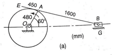
Figure 12 shows the slider crank mechanism along with velocity and acceleration diagram.
Step 1: Now write the acceleration equation


Here, the crank OA have constant angular velocity hence, the acceleration of A relative to O has only the centripetal component and the slider moves in the straight line so it does not have centripetal component.
Step 2: Prepare the acceleration table:
Table.3. Acceleration vector table for slider crank mechanism
S.No. | Vector | Magnitude | Direction | Sense |
1. |
|
|
| O |
2. |
|
|
| A |
3. |
| - |
| - |
4. |
| - |
| - |
Construction of acceleration diagram


Vector o1b1 represents the acceleration of the slider B.
Total acceleration of B relative to A is represented by the vector a1b1.
In the given figure direction of various acceleration vectors is given in opposite to the velocity vectors in velocity direction because acceleration is not supporting the motion of the link.
Example.3. For the configuration of slider-crank mechanism shown in figure (a) with velocity diagram in figure (b). Calculate the:
(i) acceleration of the slider B.
(ii) acceleration of the point E
(iii) angular acceleration of link AB.
When OA rotates at 20 rad/s counter-clockwise.
Solution.
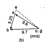
Given: a = 20 rad/s in ccw, OA= 480 mm, AB = 1600 mm, AE= 450mm.

Note: Generally, in order to calculate the acceleration first we have to draw the velocity diagram. Here it is given in question itself in figure (b).
Now write the governing vector equation for acceleration.


Now set the vector table for acceleration
S.No. | Vector | Magnitude (m/s2) | Direction | Sense |
1. |
|
|
| O |
2. |
|
|
| A |
3. |
| - |
| - |
4. |
| - |
| - |
The acceleration diagram is to be drawn as follows:
a) Select the pole point o1 and g1.
b) Draw vector  .
.
c) Add the vector  to vector
  .
.
d) For the vector  , draw a line perpendicular to AB through the head ba of the vector
  .
.
e) For the vector  draw a line through g1 parallel to the line of motion of the slider.
(i) Acceleration of slider at B, by measurement.

Direction of fb is same as of vb; hence slider is accelerating.
(ii) Now we can locate the point e1 on b1a1 by producing such that

Hence,

(iii) 
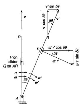
If the body moves in a fixed frame or with respect to a fixed body it has two components of acceleration i.e. centripetal and tangential component, and we use above analysis to obtain the acceleration. When a body moves in moving frame or with respect to a body which is moving itself such as motion of slider on a rotating link, we use following analysis to calculate its acceleration.
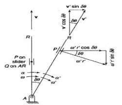
Figure.13. Motion of slider on a rotating link
Let us consider slider represented by Q slides with velocity v over a rotating link AR which rotates with an angular velocity in clockwise direction and have an angular acceleration of in clockwise direction at the given instant.
Let us take a point P on the slider to analyses the motion of slider on the link AR. It is assumed that f is the linear acceleration of slider on the link AR and r is the radial distance of point P.
Now acceleration of point P parallel to AR is given by:

In this case the slider is having acceleration radially outward direction hence taken positive, it will be negative if slider is accelerated while moving inward of retarded while moving outward.
Similarly, acceleration of P perpendicular to AR is given by:


Here the acceleration of P perpendicular to AR has two components one is the tangential acceleration of AR and the term 2v which is known as the Coriolis component of acceleration.
Coriolis component will always be positive if v and are of same sign i.e. both are either positive or negative. Positive implies the rotation in clockwise direction while positive v is the motion in radially outward direction.
Total acceleration of point P can be obtained by calculating the vector sum of the acceleration of P along the AR vector and perpendicular to the AR vector, which is given by:


Where


