There are plenty of forces such as reciprocating, rotary, oscillatory, vibratory etc. present in any of the machine element. Out of the above-mentioned forces rotary and reciprocating forces are mostly predominant. These forces can produce net unbalanced force or net unbalanced moment. The net unbalanced force may cause static loading on the system where as net unbalanced moment may cause dynamic loading on the system. These unbalanced dynamic and static loads can cause the failure of the vital element of machine component. Therefore, they must be balanced to avoid such circumstances. In this chapter we will focus on balancing of rotating masses.
Let us consider a rotating mass m with radius of rotation r with angular velocity as shown in figure 1. mb be the balancing mass rotating with angular velocity having radius of rotation rb

Figure.1. Balancing of single mass system by a single mass
Fc and Fcb be the centripetal force exerted by unbalanced and balancing mass on the shaft respectively given by:


Now equating the centrifugal forces.


Form above equation we can conclude that
a) To have balanced mass negligible small, radius of rotation of balanced mass should be as high as possible.
b) In case of high balancing mass, the balancing mass should be kept at the wheel.
c) By keeping the balancing weight on the wheel, a net unbalanced couple will be generated. Which is more dangerous than unbalanced force because unbalanced couple will generate dynamic loading in the system. Hence, it results in quick failure.
Balancing of single mass unbalanced system with two masses in different planes
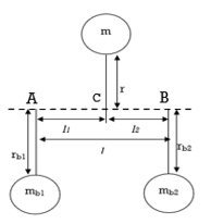
Figure.2 Space diagram for case 1
Case-1 when unbalanced mass lie between the two balancing masses
Static balancing
 By balancing centrifugal force on the system.


Since the weakest part of this system is the bearings where the balancing masses are supported. Hence, there should not be any unbalanced couple at these points and the bearing at which the unbalanced mass is supported which an integral part of the system and strong enough to carry any unbalanced couple,
Now, for dynamic balancing
 Balancing the moment at A.


 Balancing the moment at B.


From equation 1, 2 and 3 the system will be balanced completely.
Case-I1 when unbalanced mass does not lie between the two balancing masses
Consider the figure 3 in which the unbalanced mass m is rotating at a radius r with angular velocity as shown in figure 3 relative to two-balancing weight mb1 and mb2 rotating at radius rb1 and rb2 with the angular velocity respectively and l1 and l be the distance of balancing masses from the unbalanced mass and the total distance between the balancing masses is l2.
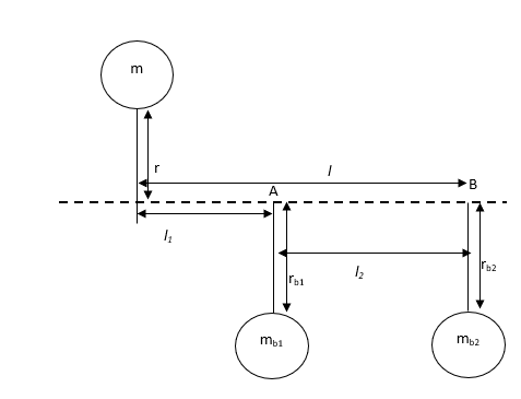
Figure.3 space diagram for case II
Static balancing
 By balancing centrifugal force on the system.


Now, for dynamic balancing
 Balancing the moment at A.


 Balancing the moment at B.


From equation 4, 5 and 6 the system will be balanced completely.
Consider the figure 4 in which unbalanced masses are represented by m1, m2, m3 and m4 rotating at radius of rotation r1, r2, r3 and r4 make angle 1, 2, 3, and 4 with angular velocity . A balancing mass of mass mb1 is placed at a radius of rotation rb making an angle .
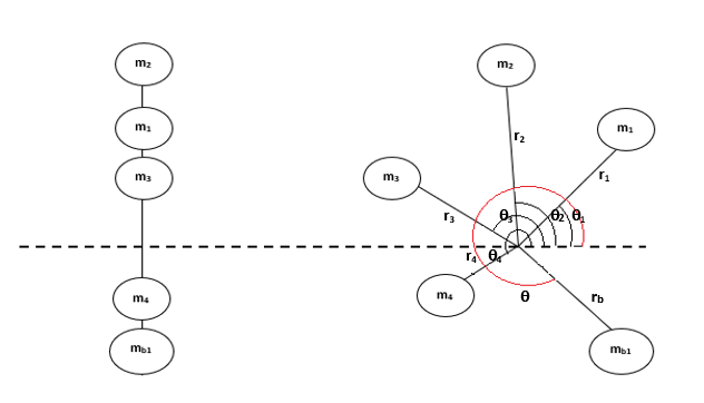
Figure.4. Balancing of several masses in same plane
Analytical method
We can find out position () and magnitude of balancing mass (mb) analytically as follows:
a) Calculate the centrifugal force exerted by each mass on the rotating shaft.
b) Resolve these forces in horizontal and vertical components. And obtain the sum of horizontal and vertical components as follows:


Now, net force


Angle ’ angle made by resultant of the force due to mass m1, m2, m3 and m4.

To balance the system of single balancing force is added which is equal in magnitude to the resultant force but in opposite direction. Hence,

Graphical method
We can also use the graphical approach to obtain the position and the magnitude of the balancing mass as follows.
a) First of all, we have to draw the space diagram for the system as shown in figure 5.
b) Calculate the centrifugal force exerted by each mass on the rotating shaft.
c) Now draw the vector diagram as shown in figure 5 with a suitable scale. Vector ab, bc, cd and de represents the force vectors due mass m1, m2, m3 and m4.
d) Now use polygon law of vectors to find the resultant force, represented by vector ae.
e) The balancing force will be equal to this resultant force vector but acts in opposite direction.
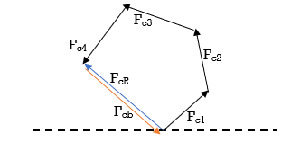
Figure.5 Vector diagram for the unbalanced system
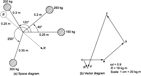
Example 1. Four masses 150, 250, 200 and 300 kg are rotating in the same plane at radii of 0.25, 0.2, 0.3 and 0.35 m, respectively. Their angular location is 40°, 120° and 250° from mass 150 kg, respectively, measured in counter-clockwise direction. Find the position and magnitude of the balance mass required, if its radius of rotation is 0.25 m.
Solution.
This problem can be solved by both graphically and analytically. Figure (a) shows the space diagram for the system of masses. Figure (b) shows the vector diagram of the system for graphical solution.
Analytical solution
For analytical solution we can make the following table
m (kg) | r (m) | mr (kgm) | (deg) | FH= mrcos (kgm) | Fv= mrsin (kgm) |
150 | 0.25 | 37.5 | 0 | 37.5 | 0 |
250 | 0.20 | 50.0 | 40 | 38.5 | 32.14 |
200 | 0.30 | 60.0 | 120 | -30.0 | 51.96 |
300 | 0.35 | 105.0 | 250 | -35.9 | -98.67 |
From Table 12.1

Resultant,


Let B be the balancing mass


Let r be the angle of resultant with 150 kg mass, then


The angle of balancing mass will be


Consider the figure 6 in which unbalanced masses are represented by m1, m2, m3 and m4 rotating at radius of rotation r1, r2, r3 and r4 make angle 1, 2, 3, and 4 with angular velocity . A balancing mass of mass mb1 and mb2 is placed at a radius of rotation rb1 and rb2 making an angle b1 and b2.
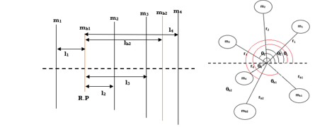
Figure.6. Space diagram for several rotating masses in different planes by two revolving masses in suitable planes
To solve such problem one of the balancing mass planes is considered as reference plane (R.P.).
Let plane of mb1 is taken as the reference plane.
Plane lying left to R.P is considered having negative distance and planes lying right to this RP are considered having positive distance.\
Now prepare following table.
m (kg) | r (m) | l (m) | (deg) | mr (kgm) | mrl (kgm2) | FH= mrcos (kgm) | Fv= mrsin (kgm) | MH= mrlcos (kgm2) | Mv= mrlsin (kgm2) |
|
|
|
|
|
|
|
|
|
|
Now applying moment balance equation, we can obtain the value of mb2 and b2 if rb2 and lb2 is known.
Find


For position b2


Similarly, applying force balance equation, we can obtain the value of mb1 and b1 if rb1 and lb1 is known.
Find


For position b1


Example.2. A small shaft carries four masses m1, m2, m3 and m4 of magnitude 200 kg, 300 kg, 400 kg and 200 kg respectively and revolving at radii 80 mm, 0 mm, 60mm and 80mm in planes measured from m1 at 300mm, 400mm and 700mm angle between the crank is measured in ccw from m1 to m2 is 45°, m2 to m3 70° and from m3 to m4 is 120°. The balancing masses are to be placed of magnitude mb1 and mb2. The distance between m1 and mb1 planes is 100mm and distance between the planes containing mb1 and mb2 is 400mm. if the radius of rotation of mb1 and mb2 is 100mm. find the magnitude and angular position of balancing masses.
Solution.
Make the space diagram for the given problem according to description.
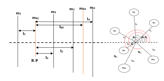
l1=100 mm, l2= 200 mm, l3=300 mm, l4= 700 mm, lb2=400mm
r1= 80 mm, r2= 70 mm, r3= 60 mm, r4= 80 mm, rb1=rb2= 100 mm
1=0°, 2=45°, 3=115°, 4=235°,b1=? and b2=?
m1= 200 kg, m2= 300 kg, m3= 400 kg, m4=200 kg, mb1=? and mb2=?
Prepare the given table
m (kg) | r (m) | l (m) | (deg) | mr (kgm) | mrl (kgm2) | FH= mrcos (kgm) | Fv= mrsin (kgm) | MH= mrlcos (kgm2) | Mv= mrlsin (kgm2) |
200 | .08 | -0.1 | 0 | 16 | -1.6 | 16 | 0 | -1.6 | 0 |
300 | .07 | 0.2 | 45 | 21 | 4.2 | 14.84 | 14.84 | 2.96 | 2.96 |
400 | .06 | 0.3 | 115 | 24 | 7.2 | -10.14 | 21.75 | -3.04 | 6.52 |
200 | .08 | 0.6 | 235 | 16 | 9.6 | -9.18 | -13.11 | -5.5 | -7.86 |
Calculations for mb2 and b2


Calculations for mb2 and b2


For position b1


Hence mb1 = 282.59 kg, mb2 = 184 kg, b1 = 167.28° and b2 = 103.04°.
