Unit 3
Metal Cutting
Machining isn't only 1 process; it's a gaggle of processes. The common feature is that the use of a cutting tool to create a chip that's off from the workpart. To perform the operation, relative motion is needed between the tool and work. This relative motion is achieved in most machining operations by means that of a primary motion, referred to as the cutting speed, and a secondary motion, referred to as the feed. The form of the tool and its penetration into the surface, combined with these motions, produces the required geometry of the ensuing surface.

Figure 1: (a) A cross-sectional view of the machining process. (b) Tool with negative rake angle; compare with positive rake angle in (a).
3.1.1 Kinds of Machining Operations:
There are several kinds of machining operations, every of that is capable of generating a part geometry and surface texture. Except for currently it's acceptable to spot and outline the 3 commonest types: turning, drilling, and milling, illustrated in below figure. In turning, a cutting tool with one cutting edge is employed to get rid of material from a rotating workpiece to come up with a cylindrical form. The speed motion in turning is provided by the rotating workpart, and also the feed motion is achieved by the cutting tool moving slowly during a direction parallel to the axis of rotation of the workpiece. Drilling is employed to form a spherical hole. It’s accomplished by a rotating tool that usually has 2 cutting edges. The tool is fed during a direction parallel to its axis of rotation into the workpart to create the spherical hole. In milling, a rotating tool with multiple cutting edges is fed slowly across the work material to come up with a plane or straight surface. The direction of the feed motion is perpendicular to the tool’s axis of rotation. The speed motion is provided by the rotating edge cutter. The 2 basic kinds of edge are peripheral edge and face milling. Alternative standard machining operations embody shaping, planning, broaching, and sawing. Also, grinding and similar abrasive operations are typically enclosed at intervals the class of machining. These processes normally follow the traditional machining operations and are accustomed accomplish a superior surface finish on the workpart.
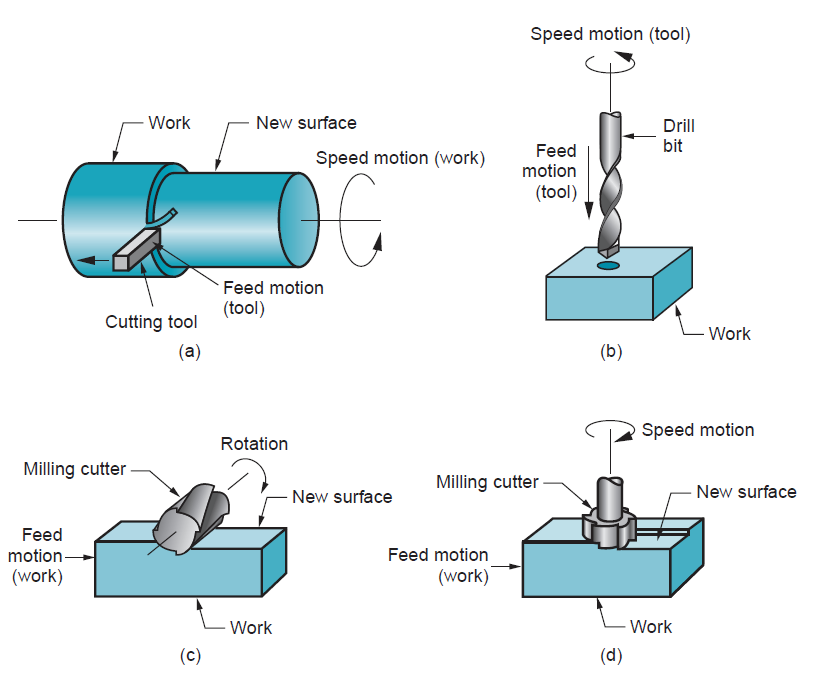
Figure 2: The three most common types of machining processes: (a) turning, (b) drilling, and two forms of milling: (c) peripheral milling, and (d) face milling.
3.1.2 The Cutting tool:
A cutting tool has one or additional sharp cutting edges and is created of a fabric that's more durable than the work material. The cutting edge serves to separate a chip from the parent work material. Connected to the cutting edge are 2 surfaces of the tool: the rake face and also the flank. The rake face, that directs the flow of the fresh fashioned chip, is directed at an exact angle referred to as the rake angle α. it's measured relative to a plane perpendicular to the surface. The rake angle may be positive. The flank of the tool provides a clearance between the tool and also the fresh generated work surface, therefore protective the surface from abrasion, which would degrade the end. This flank surface is directed at angle referred to as the relief angle.
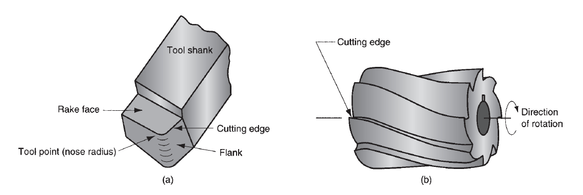
Figure 3: (a) A single-point tool showing rake face, flank, and tool point; and(b)a helical milling cutter, representative of tools with multiple cutting edges.
Single and multi-point cutting:
Most cutting tools in practice have more complicated geometries than those in figure. There are 2 basic sorts,
(a) single-point tools and
(b) multiple-cutting-edge tools.
A single-point tool has one cutting edge and is employed for operations admire turning. There's one tool purpose from that the name of this cutting tool comes. Throughout machining, the purpose of the tool penetrates below the first surface of the part. The purpose is sometimes rounded to an exact radius, referred to as the nose radius.
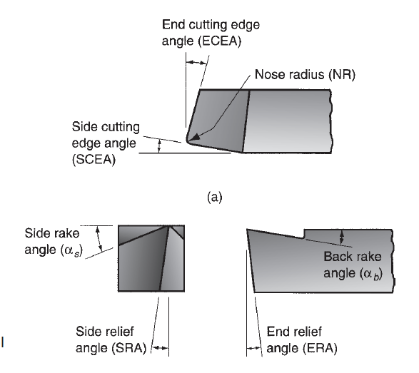
Figure 4: Single Pont cutting tool geometry
Multiple-cutting-edge tools have over one cutting edge and typically accomplish their motion relative to the workpart by rotating. Drilling and edge use rotating multiple-cutting-edge tools. Figure (b) shows a coiling edge cutter utilized in peripheral milling. Although the form is kind of totally different from a single point tool, several components of tool geometry are similar.

Figure 5: Multiple cutting edge tool geometry
By definition, orthogonal cutting uses a wedge-shaped tool during which the cutting edge is perpendicular to the direction of cutting speed. Because the tool is forced into the fabric, the chip is created by shear deformation on a plane referred to as the shear plane that is directed at angle Ø with the surface of the work. Solely at the sharp cutting edge of the tool will failure of the fabric occur, leading to separation of the chip from the parent material.
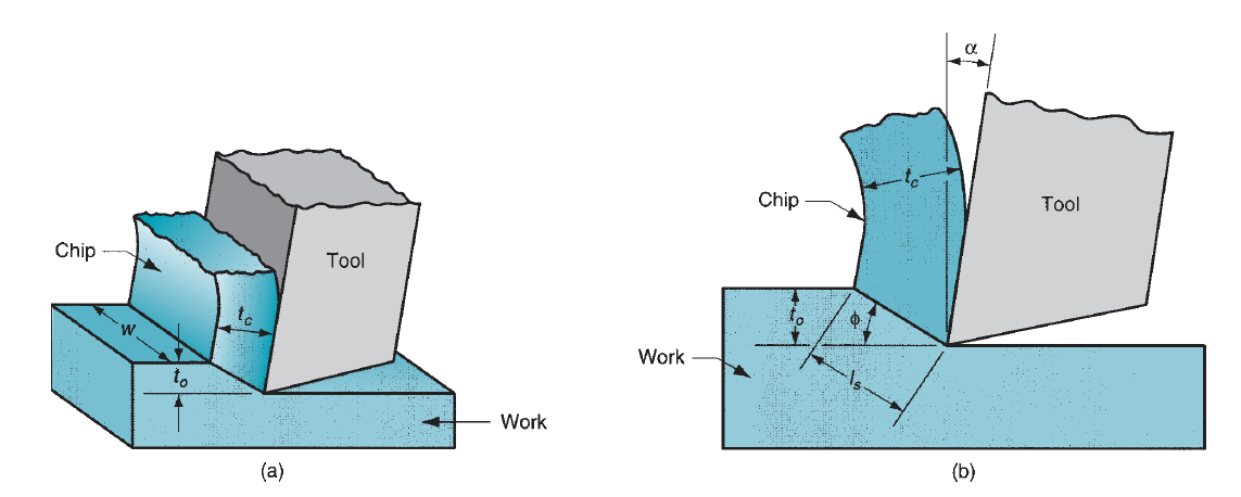
Figure 6: Orthogonal cutting: (a) as a three-dimensional process, and (b) how it reduces to two dimensions in the side view.
On the shear plane, wherever the majority of the energy is consumed in machining, the fabric is plastically distorted. The tool in orthogonal cutting has solely 2 components of geometry: (1) rake angle and (2) clearance angle. As indicated antecedently, the rake angle α determines the direction that the chip flows because it is created from the workpart; and also the clearance angle provides a little clearance between the tool flank and the fresh generated surface. Throughout cutting, the cutting edge of the tool is positioned an exact distance below the first surface. This corresponds to the thickness of the chip before chip formation, to. Because the chip is created on the shear plane, its thickness will increase to tc. The magnitude relation of to to tc is named the chip thickness ratio (or merely the chip ratio) r:

Since the chip thickness once cutting is usually larger than the corresponding thickness before cutting, the chip magnitude relation can forever be not up to one. Additionally to to, the orthogonal cut incorporates a breadth dimension w, even supposing this dimension doesn't contribute abundant to the analysis in orthogonal cutting. The geometry of the orthogonal cutting model permits us to determine a very important relationship between the chip thickness magnitude relation, the rake angle, and also the shear angle. Let ls be the length of the shear plane. We can build the substitutions:
to = ls sin , and tc = lscos(
 ). Thus,

This will be rearranged to work out  as follows:

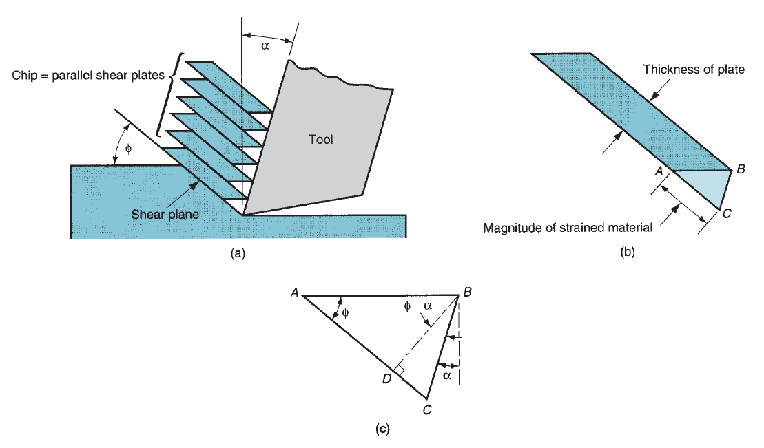
Figure 7: Shear strain during chip formation: (a) chip formation depicted as a series of parallel plates sliding relative to each other; (b) one of the plates isolated to illustrate the definition of shear strain based on this parallel plate model; and (c) shear strain triangle
The shear strain that happens on the shear plane may be calculable by examining below figure. (a) Shows shear deformation approximated by a series of parallel plates slippery against each other to create the chip. As per our definition of shear strain every plate experiences the shear strain shown in figure (b). Relating part (c), this will be expressed as

This may be reduced to the subsequent definition of shear strain in metal cutting as:

Take into account the forces engaged on the chip throughout orthogonal cutting. The forces applied against the chip by the tool may be separated into 2 reciprocally perpendicular components: friction force and traditional force to friction. The friction force F is that the resistance force resisting the flow of the chip along the rake faces of the tool. The normal force to friction N is perpendicular to the friction force. These 2 elements may be accustomed outline the constant of friction between the tool and also the chip:
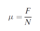
The friction force and its traditional force can be additional vectorially to create a resultant force R, that is directed at angle , referred to as the friction angle. Thefriction angle is said to the constant of friction as

Additionally to the tool forces engaged on the chip, there are two force components applied by the piece of work on the chip: shear force and traditional force to shear. The shear force Fs is that the force that causes shear deformation to occur within the shear plane, and also the traditional force to shear Fn is perpendicular to the shear force. Based on the shear force, we can outline the shear stress that acts on the shear plane between the work and also the chip:
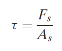
Wherever As = space of the shear plane. This shear plane space may be calculated as
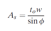
The shear stress represents the extent of stress needed to perform the machining operation. Therefore, this stress is capable the shear strength of the work material ( = S) beneath the conditions at that cutting happens. Vector addition of the 2 force elements Fs and Fn yields the resultant force R’. So as for the forces engaged on the chip to be in balance, this resultant R’ should be equal in magnitude, opposite in direction, and linear with the resultant R.
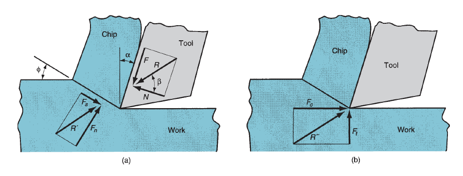
Figure 8: Forces in metal cutting: (a) forces acting on the chip in orthogonal cutting, and (b) forces acting on the tool that can be measured.
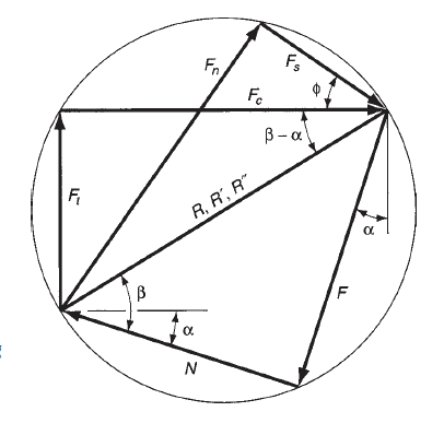
Figure 9: Force diagram showing geometric relationships between F, N, Fs, Fn, Fc, and Ft.
None of the four force elements F, N, Fs, and Fn may be directly measured during a machining operation, as a result of the directions during which they're applied vary with totally different tool geometries and cutting conditions. However, it's doable for the cutting tool to be instrumented employing a force measuring system referred to as a measuring device, so 2 further force elements acting against the tool may be directly measured: cutting force and thrust force. The cutting force Fc is within the direction of cutting, an equivalent direction because the cutting speed v, and also the thrust force Ft is perpendicular to the cutting force and is related to the chip thickness before the move. Beside their resultant force R”. The several directions of those forces are illustrious; therefore the force transducers within the measuring device may be aligned consequently. Equations may be derived to relate the four force elements that can't be measured to the 2 forces which will be measured. Victimization the force diagram in figure, the subsequent geometry relationships may be derived:
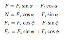
If cutting force and thrust force are illustrious, these four equations may be accustomed calculate estimates of shear force, friction force, and traditional force to friction. Supported these force estimates, shear stress and constant of friction may be determined. Note that within the special case of orthogonal cutting when the rake angle = 0, and scale back to F = Ft and N = Fc, severally. Thus, during this special case, friction force and its traditional force might be directly measured by the measuring device.
3.3.1 The Merchant Equation:
One amongst the necessary relationships in metal cutting was derived by Eugene Merchant. Its derivation was supported the belief of orthogonal cutting, however its general validity extends to three-dimensional machining operations. Merchant started with the definition of shear stress expressed within the type of the subsequent relationship derived:
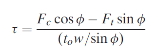
Merchant reasoned that, out of all the doable angles emanating from the cutting edge of the tool at that shear deformation might occur, there's one angle  that predominates. This is often the angle at that shear stress is simply capable the shear strength of the work material, then shear deformation happens at this angle. For all alternative doable shear angles, the shear stress is a smaller amount than the shear strength; therefore chip formation cannot occur at these alternative angles. In effect, the work material can choose a shear angle that minimizes energy. This angle may be determined by taking the by-product of the shear stress S with reference to
  and setting the by-product to zero. Resolution for
  , we have a tendency to get the link named once Merchant:
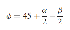
Among the assumptions within the Merchant equation is that shear strength of the work material could be a constant, unaffected by strain rate, temperature, and alternative factors. as a result of this assumption is profaned in sensible machining operations, the equation should be thought-about an approximate relationship instead of an correct mathematical equation.
We must always note that there are variations between the orthogonal models an actual machining method. First, the shear deformation method doesn't occur on a plane, however at intervals a zone. If cut were to require place across a plane of zero thickness, it might imply that the cut action should occur in a flash because it passes through the plane, instead of over some finite (although brief) period. For the fabric to behave during a realistic manner, the shear deformation must occur at intervals a skinny shear zone. Metal-cutting experiments have indicated that the thickness of the shear zone is merely a few thousandths of an in.
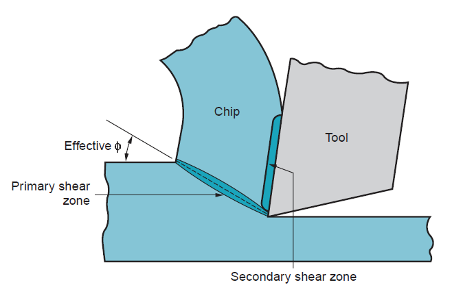
Figure 10: More realistic view of chip formation, showing shear zone rather than shear plane. Also shown is the secondary shear zone resulting from tool–chip friction.

Figure 11: Four types of chip formation in metal cutting: (a) discontinuous, (b) continuous, (c) continuous with built-up edge, (d) serrated.
Since the shear zone is therefore skinny, there's not an excellent loss of accuracy in most cases by relating it as a plane. Second, additionally to shear deformation that happens within the shear zone, another cut action happens within the chip once it's been fashioned. this extra shear is remarked as secondary shear to tell apart it from primary shear. Secondary shear results from friction between the chip and also the tool because the chip slides on the rake face of the tool. Its result will increase with enlarged friction between the tool and chip. The first and secondary shear zones may be seen in figure. Third, formation of the chip depends on the kind of fabric being machined and also the cutting conditions of the operation. Four basic kinds of chip may be distinguished:
Discontinuous chip: Once comparatively brittle materials (e.g., solid irons) are machined at low cutting speeds, the chips typically kind into separate segments (sometimes the segments are loosely attached). This tends to impart irregular texture to the machined surface. High tool–chip friction and enormous feed and depth of cut promote the formation of this chip kind.
Continuous chip: Once ductile work materials are cut at high speeds and comparatively little feeds and depths, long continuous chips are fashioned. an honest surface finish usually results once this chip kind is created. a pointy cutting edge on the tool and low tool–chip friction encourage the formation of continuous chips. Long, continuous chips (as in turning) will cause issues with respect to chip disposal and/or tangling regarding the tool. To resolve these issues, turning tools are typically equipped with chip breakers.
Continuous chip with built-up edge: once machining ductile materials at low-to-medium cutting speeds, friction between tool and chip tends to cause parts of the work material to stick to the rake face of the tool close to the cutting edge. This formation is named a settled edge (BUE). The formation of a BUE is cyclical; it forms and grows, then becomes unstable and breaks off. Abundant of the detached BUE is anxious with the chip, generally taking parts of the tool rake face with it that reduces the lifetime of the cutting tool. Parts of the detached BUE that don't seem to be carried off with the chip become imbedded within the fresh created surface, inflicting the surface to become rough.
Serrated chips: These chips are semi-continuous within the sense that they possess a saw-tooth look that's made by a rotary chip formation of alternating high shear strain followed by low shear strain. This fourth form of chip is most closely related to sure difficult-to-machine metals admire metal alloys, nickel-base super alloys, and primary solid solution unstained steels after they are machined at higher cutting speeds. However, the development is additionally found with additional common work metals (e.g., steels) after they are cut at high speeds.
3.5.1 Tool Wear: Gradual wear happens at 2 principal locations on a cutting tool: the highest rake face and also the flank. Consequently, 2 main kinds of tool wear may be distinguished: crater wear and flank wear. We are going to use a single-point tool to elucidate tool wear and also the mechanisms that cause it. Crater wear, consists of a cavity within the rake face of the tool that forms and grows from the action of the chip slippery against the surface. High stresses and temperatures characterize the tool–chip contact interface, conducive to the sporting action. The crater may be measured either by its depth or its space. Flank wear, happens on the flank, or relief face, of the tool. It results from rubbing between the fresh generated surface and also the flank face adjacent to the cutting edge. Flank wear is measured by the breadth of the wear and tear band, FW. This wear band is usually referred to as the flank wear land.
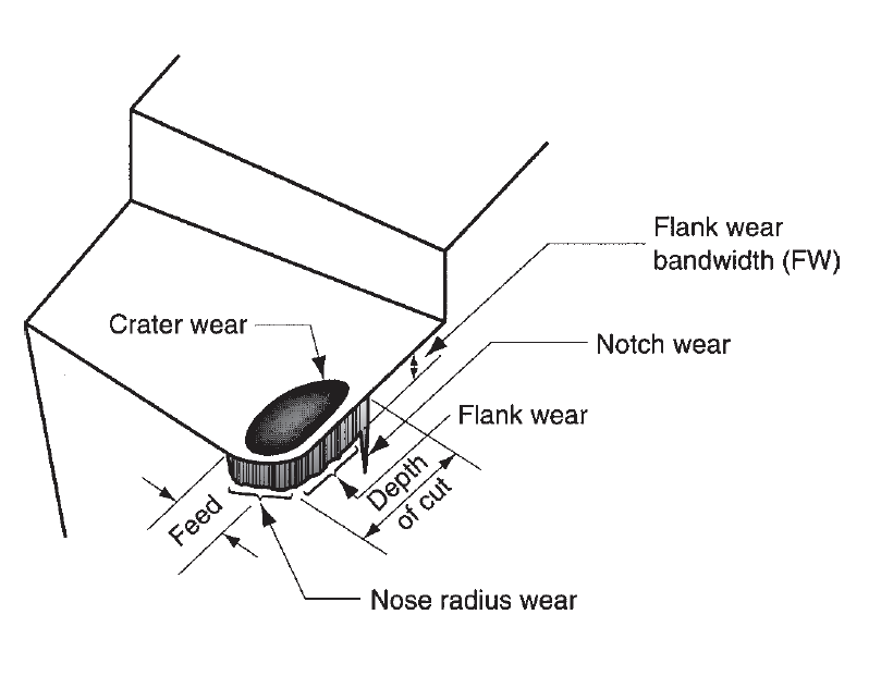
Figure 12: Diagram of worn cutting tool, showing the principal locations and types of wear that occur.
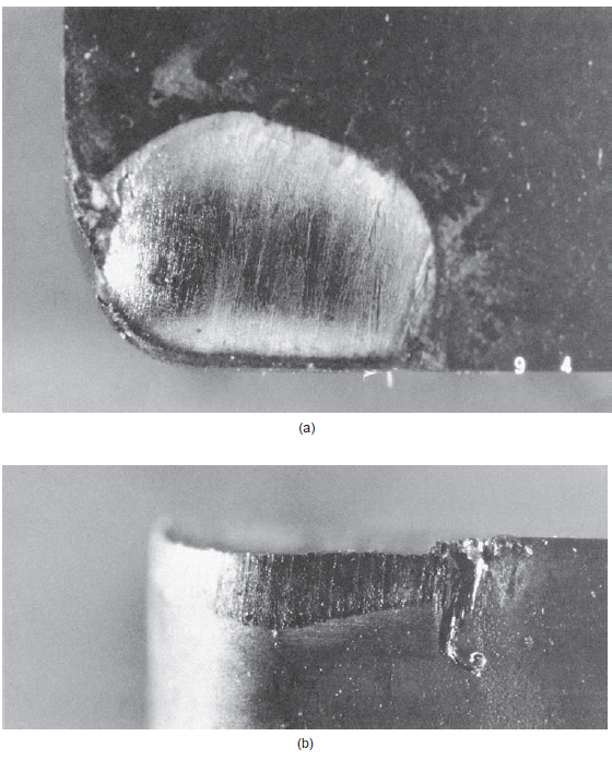
Figure 13: (a) Crater wear and (b) flank wear on a cemented carbide tool, as seen through a toolmaker’s microscope. (Courtesy of Manufacturing Technology Laboratory, Lehigh University, photos by J. C. Keefe.)
Sure options of flank wear may be known. First, extreme condition of flank wear typically seems on the cutting edge at the placement similar to the first surface of the workpart. This is often referred to as notch wear. It happens as a result of the first surface is more durable and/or additional abrasive than the inner material, that might be caused by work hardening from cold drawing or previous machining, sand particles within the surface from casting, or alternative reasons. As a consequence of the more durable surface, wear is accelerated at this location. A second region of flank wear which will be known is nose radius wear; this happens on the nose radius leading into the top cutting edge. The mechanisms that cause wear at the tool–chip and tool–work interfaces in machining may be summarized as follows:
Abrasion: This is often a mechanical sporting action caused by laborious particles within the work material gouging and removing little parts of the tool. This abrasive action happens in each flank wear and crater wear; it's a major reason for flank wear. Adhesion: Once 2 metals are forced into contact beneath high and temperature, adhesion or welding occur between them. These conditions are gift between the chip and also the rake face of the tool. As the chip flows across the tool, little particles of the tool are broken off from the surface, leading to attrition of the surface.
Diffusion: This is often a method during which exchange of atoms takes place across an in depth contact boundary between 2 materials. Within the case of tool wear, diffusion happens at the tool–chip boundary, inflicting the tool surface to become depleted of the atoms chargeable for its hardness. As this method continues, the tool surface becomes additional liable to abrasion and adhesion. Diffusion is believed to be a principal mechanism of crater wear.
Chemical reactions: The high temperatures and clean surfaces at the tool–chip interface in machining at high speeds may end up in chemical reactions, above all, oxidation, on the rake face of the tool. The oxidized layer, being softer than the parent tool material, is sheared away, exposing new material to sustain the reaction method.
Plastic deformation: Another mechanism that contributes to tool wear is plastic deformation of the cutting edge. The cutting forces engaged on the cutting edge at extreme temperature cause the sting to deform plastically, creating it additional at risk of abrasion of the tool surface. Plastic deformation contributes principally to flank wear. Most of those tool-wear mechanisms are accelerated at higher cutting speeds and temperatures. Diffusion and chemical action are particularly sensitive to elevated temperature.
3.5.2 Tool Life:
As cutting advances, the assorted wear mechanisms lead to increasing levels of wear and tear on the cutting tool. The overall relationship of tool wear versus cutting time is shown in figure. Though the link shown is for flank wear, an identical relationship occurs for crater wear. Three regions will sometimes be known within the typical wear growth curve. The first is that the break-in period, within which the cutting edge wears quickly at the start of its use. This first region happens among the primary few minutes of cutting. The break-in period is followed by wear that happens at a reasonably uniform rate. This can be referred to as the steady-state wear region. In our figure, this region is pictured as a linear operates of your time, though there are deviations from the line in actual machining. Finally, wear reaches tier at which the wear rate begins to accelerate. This marks the start of the failure region, in which cutting temperatures are higher, and also the general potency of the machining method is reduced. If allowed to continue, the tool finally fails by temperature failure. The slope of the tool wear curve within the steady-state region is full of work material and cutting conditions. More durable work materials cause the wear and tear rate (slope of the tool wear curve) to extend. Exaggerated speed, feed, and depth of cut have an identical impact, with speed being the foremost necessary of the 3. If the tools wear curves are aforethought for several totally different cutting speeds. As cutting speed is increased, wear rate will increase therefore the same level of wear and tear is reached in less time.
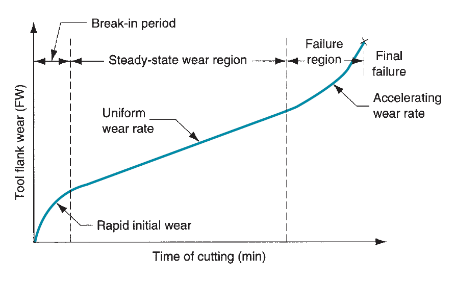
Figure 14: Tool wear as a function of cutting time. Flank wear (FW) is used here as the measure of tool wear. Crater wear follows a similar growth curve.
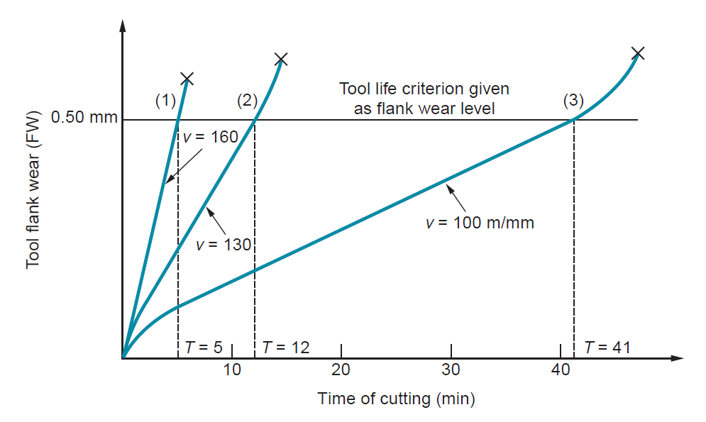
Figure 15: Effect of cutting speed on tool flank wear (FW) for three cutting speeds. Hypothetical values of speed and tool life are shown for a tool life criterion of 0.50-mm flank wear.
Tool life is outlined as the length of cutting time that the tool is often used. Operating the tool till final ruinous failure is a method of shaping tool life. This can be indicated in figure by the tip of every tool wear curve. However, in production, it's usually a disadvantage to use the tool till this failure happens owing to difficulties in re-sharpening the tool and issues with surface quality. As another, tier of tool wear can be elite as a criterion of tool life, and also the tool is replaced when wear reaches that level. A convenient tool life criterion may be a sure flank wears worth, such as 0.5 mm (0.020 in), illustrated because the horizontal line on the graph. When every of the 3 wear curves intersect that line, the lifetime of the corresponding tool is outlined as complete. If the intersection points are projected right down to the time axis, the values of tool life are often known, as we've done.
Taylor Tool Life Equation:
Discovery of this relationship around 1900 is attributable to F.W. Taylor. It will be expressed in equation type and is named the Taylor tool life equation:

where v = cutting speed, m/min (ft/min); T = tool life, min; and n and C are parameters whose values rely upon feed, depth of cut, work material, tooling (material in particular), and also the tool life criterion used. The worth of n is relative constant for a given tool material, whereas the worth of C depends on tool material, work material, and cutting conditions.
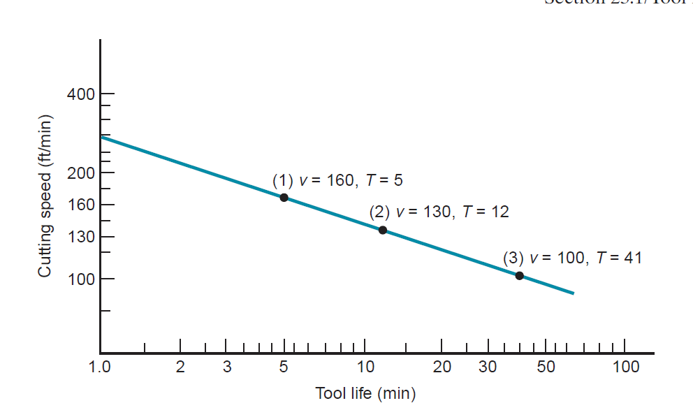
Figure 16: Natural log–log plot of cutting speed vs. tool life.
Basically, equation states that higher cutting speeds lead to shorter tool lives. Relating the parameters n and C to above figure, n is that the slope of the plot (expressed in linear terms instead of within the scale of the axes), and C is that the intercept on the speed axis. C represents the cutting speed that ends up in a 1-min tool life. The drawback with equation is that the units on the right-hand facet of the equation are not per the units on the left-hand side. to form the units consistent, the equation ought to be expressed within the form

where Tref = a reference worth for C. Tref is just one min once m/min (ft/min) and minutes are used for v and T, severally. The advantage of this equation is seen once it's desired to use the Taylor equation with units although m/min (ft/min) and minutes-for example, if cutting speed were expressed as m/sec and power life as sec. during this case, impure would be sixty sec and C would therefore be identical speed worth, though regenerate to units of m/sec. The slope n would have identical numerical worth.
The 3 modes of tool failure permit US to spot three necessary properties needed during a tool material:
Toughness: To avoid fracture failure, the tool material should possess high toughness. Toughness is that the capability of a fabric to soak up energy while not failing. It’s typically characterized by a mix of strength and malleability within the material.
Hot hardness: Hot hardness is that the ability of a fabric to retain its hardness at high temperatures. This is often needed attributable to the high-temperature surroundings during which the tool operates.
Wear resistance: Hardness is that the single most significant property required resisting abrasive wear. All cutting-tool materials should be laborious. However, wear resistance in metal cutting depends on over simply tool hardness, attributable to the opposite tool-wear mechanisms. Alternative characteristics poignant wear resistance embody surface finish on the tool (a drum sander surface means that a lower constant of friction), chemistry of tool and work materials, and whether or not a cutting fluid is employed.
Cutting-tool materials accomplish this mixture of properties in varied degrees. During this section, the subsequent cutting-tool materials are discussed:
(1) Tool steel (high-speed steel) and its predecessors, plain carbon and low alloy steels;
(2) Cast cobalt alloys;
(3) Cemented carbides, cermets, and coated carbides;
(4) Ceramics;
(5) Artificial diamond and cubic boron nitride.
Before examining these individual materials, a short summary and technical comparison are going to be useful. Commercially, the foremost necessary tool materials are tool steel and cemented carbides, cermets, and coated carbides. These 2 classes account for over 90% of the cutting tools utilized in machining operations. The properties are those concerning the necessities of a cutting tool: hardness, toughness, and hot hardness.
A cutting fluid is any liquid or gas that's applied on to the machining operation to enhance cutting performance. Cutting fluids address 2 main problems:
(1) Heat generation at the shear zone and friction zone, and
(2) Friction at the tool–chip and tool–work interfaces.
Additionally to removing heat and reducing friction, cutting fluids offer further advantages, admire laundry away chips (especially in grinding and milling), reducing the temperature of the workpart for easier handling, reducing cutting forces and power needs, rising dimensional stability of the workpart, and rising surface finish.
Kinds of Cutting Fluids:
A spread of cutting fluids is commercially obtainable. It’s acceptable to debate them 1st consistent with operate then to classify them according to chemical formulation.
Cutting Fluid Functions: There are 2 general classes of cutting fluids, similar to the 2 main issues they're designed to address: coolants and lubricants. Coolants are cutting fluids designed to scale back the results of warmth within the machining operation. They need a restricted result on the number of warmth energy generated in cutting; instead, they take away the warmth that's generated, thereby reducing the temperature of tool and piece of work. This helps to prolong the lifetime of the cutting tool. The capability of a cutting fluid to scale back temperatures in machining depends on its thermal properties. Heat energy and thermal conduction are the foremost necessary properties. Water has high heat energy and thermal conduction relative to alternative liquids, that is why water is employed because the base in coolant-type cutting fluids. These properties allow the fluid to draw heat off from the operation, thereby reducing the temperature of the cutting tool. Coolant-type cutting fluids appear to be best at comparatively high cutting speeds, during which heat generation and high temperatures are issues. They’re best on tool materials that are most liable to temperature failures, admire high speed steels, and are used oft in turning and edge operations, during which massive amounts of warmth are generated.
Lubricants are typically oil-based fluids (because oils possess sensible lubricating qualities) developed to scale back friction at the tool–chip and tool–work interfaces. Lubricator cutting fluids operate by extreme pressure lubrication, a special type of lubrication that involves formation of skinny solid salt layers on the recent, clean metal surfaces through chemical action with the lubricator. Compounds of sulfur, chlorine, and phosphorus within the lubricator cause the formation of those surface layers, that act to separate the 2 metal surfaces (i.e., chip and tool).These extreme pressure films are significantly more effective in reducing friction in metal cutting than standard lubrication, that is predicated on the presence of liquid films between the 2 surfaces. Lubricant-type cutting fluids are best at lower cutting speeds. They have a tendency to lose their effectiveness at high speeds as a result of the motion of the cut these speeds prevents the cutting fluid from reaching the tool–chip interface. Additionally, high cutting temperatures at these speeds cause the oils to vaporize before they'll lubricate. Machining operations admire drilling and sound typically like lubricants. In these operations, settled edge formation is unintelligent, and force on the tool is reduced. Though the principal purpose of a lubricator is to scale back friction, it additionally reduces the temperature within the operation through many mechanisms. First, the precise heat and thermal conduction of the lubricator facilitate to get rid of heat from the operation, thereby reducing temperatures. Second, as a result of friction is reduced, the warmth generated from friction is additionally reduced. Third, a lower constant of friction means that a lower friction angle. According to Merchant’s equation, a lower friction angle causes the shear angle to extend, thus reducing the number of warmth energy generated within the shear zone. there's usually overlapping result between the 2 kinds of cutting fluids. Coolants are developed with ingredients that facilitate scale back friction. And lubricants have thermal properties that, though not nearly as good as those of water, act to get rid of heat from the cutting operation. Cutting fluids (both coolants and lubricants) manifest their result on the Taylor tool life equation through higher C values. Will increase of 10% to 40% are typical. The slope n isn't considerably affected.
Chemical Formulation of Cutting Fluids: There are four classes of cutting fluids consistent with chemical formulation:
(1) Cutting oils,
(2) Blended oils,
(3) Semi-chemical fluids, and
(4) Chemical fluids.
All of those cutting fluids offer each fluid and lubricating functions. The cutting oils are best as lubricants, whereas the opposite 3 classes are simpler as coolants as a result of their primarily water.
Cutting oils are supported oil derived from crude, animal, marine, or vegetable origin. Mineral oils (petroleum based) are the principal kind attributable to their abundance and usually fascinating lubricating characteristics. To realize most lubricity, many kinds of oils are typically combined within the same fluid. Chemical additives also are mixed with the oils to extend lubricating qualities. These additives contain compounds of sulfur, chlorine, and phosphorus, and are designed to react chemically with the chip and power surfaces to create solid films (extreme pressure lubrication) that help to avoid metal-to-metal contact between the two.
Blended oils contain oil droplets suspended in water. The fluid is created by mixing oil (usually mineral oil) in water victimization emulsifying agent to push blending and stability of the emulsion. A typical magnitude relation of water to oil is 30:1. Chemical additives supported sulfur, chlorine, and phosphorus are typically accustomed promote extreme pressure lubrication. As a result of they contain each oil and water, the blended oils mix cooling and lubricating qualities in one cutting fluid.
Chemical fluids are chemicals during a water answer instead of oils in emulsion. The dissolved chemicals embody compounds of sulfur, chlorine, and phosphorus, and wetting agents. The chemicals are meant to produce some extent of lubrication to the answer. Chemical fluids offer sensible fluid qualities however their lubricating qualities are not up to the opposite cutting fluid sorts. Semi-chemical fluids have little amounts of blended oil additional to extend the lubricating characteristics of the cutting fluid. In effect, they're a hybrid category between chemical fluids and blended oils.
Properties of the work material have a major influence on the success of the machining operation. These properties and alternative characteristics of the work are typically summarized within the term ‘‘machinability.’’ Machinability denotes the relative ease with that a fabric (usually a metal) may be machined victimization acceptable tooling and cutting conditions. There is numerous criteria accustomed measure machinability, the foremost necessary of that are: (1) tool life, (2) forces and power, (3) surface finish, and (4) easy chip disposal. Though machinability usually refers to the work material, it ought to be recognized that machining performance depends on over simply material. The kind of machining operation, tooling, and cutting conditions also are necessary factors. Additionally, the machinability criterion could be a supply of variation. One material could yield an extended tool life, whereas another material provides a much better surface finish. All of those factors build analysis of machinability troublesome.
Machinability testing typically involves a comparison of labor materials. The machining performance of a take a look at material is measured relative thereto of a base (standard) material. Possible measures of performance in machinability testing include: (1) tool life, (2) tool wear, (3) cutting force, (4) power within the operation, (5) cutting temperature, and (6) material removal rate beneath customary take a look at conditions. The relative performance is expressed as indicant, referred to as the machinability rating (MR).The base material used because the customary is given a machinability rating of 1.00. B1112 steel is commonly used because the base material in machinability comparisons. Materials that are easier to machine than the bottom have ratings larger than 1.00, and materials that are more troublesome to machine have ratings not up to 1.00. Machinability ratings are typically expressed as percentages instead of index numbers
As a result of machining is commonly the producing method that determines the ultimate geometry and dimensions of the part, it's additionally the method that determines the part’s surface texture. Allow us to examine however surface finish is set during a machining operation. The roughness of a machined surface depends on several factors which will be sorted as follows: (1) geometric factors, (2) work material factors, and (3) vibration and machine tool factors. Our discussion of surface finish during this section examines these factors and their effects.
Geometric Factors:
These are the machining parameters that confirm the surface geometry of a machined part. They include: (1) form of machining operation; (2) cutting tool geometry, most significantly nose radius; and (3) feed. The surface geometry that might result from these factors is remarked because the ‘‘ideal’’ or ‘‘theoretical’’ surface roughness, that is that the end that might be obtained within the absence of labor material, vibration, and machine factors. Form of operation refers to the machining method accustomed generate the surface. For instance, peripheral milling, facing edge, and shaping all manufacture a flat surface; but, the surface geometry is totally different for every operation attributable to variations in tool form and also the manner the tool interacts with the surface.
Tool geometry and feed mix to create the surface geometry. The form of the tool purpose is that the necessary tool geometry issue. With an equivalent feed, a bigger nose radius causes the feed marks to be less pronounced, therefore resulting in a much better end. If 2 feeds are compared with an equivalent nose radius, the larger feed will increase the separation between feed marks, resulting in a rise within the price of ideal surface roughness. If feed rate is massive enough and also the nose radius is little enough so the top cutting edge participates in making the new surface, then the top stylish angle can have an effect on surface geometry. During this case, the next ECEA will lead to a higher surface roughness price.
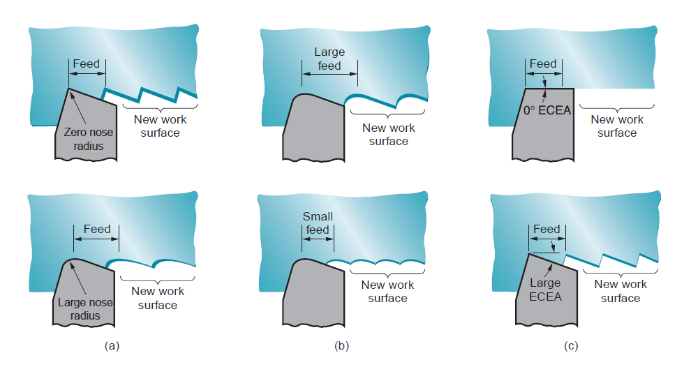
Figure 17: Effect of geometric factors in determining the theoretical finish on a work surface for single-point tools: (a) effect of nose radius, (b) effect of feed, and (c) effect of end cutting-edge angle.
In theory, a zero ECEA would yield a wonderfully swish surface; but, imperfections within the tool, work material, and machining method preclude achieving such a perfect end. the results of nose radius feed may be combined in an equation to predict the best average roughness for a surface made by a single-point tool. The equation applies to operations admire turning, shaping, and planning

Where Ri = theoretical arithmetic average surface roughness, millimeter (in); f = feed, millimeter (in); and NR = nose radius on the tool purpose, mm (in). The equation assumes that the nose radius isn't zero which feed and nose radius is going to be the principal factors that confirm the geometry of the surface. The values for Ri will be in units of millimeter (in), which may be regenerate to  (
( -in). The equation may also be accustomed estimate the best surface roughness in face edge with insert tooling, victimization f to represent the chip load (feed per tooth). Equation assumes a pointy cutting tool. Because the tool wears, the form of the cutting purpose changes that is mirrored within the geometry of the surface. For slight amounts of tool wear, the result isn't noticeable. However, once tool wear becomes vital, particularly nose radius wear, surface roughness deteriorates compared with the best values given by the preceding equations.
Work Material Factors:
Achieving the best surface finish isn't doable in most machining operations attributable to factors concerning the work material and its interaction with the tool. Work material factors that have an effect on end include: (1) settled edge effects-as the BUE cyclically forms and breaks away, particles are deposited on the fresh created surface, inflicting it to possess a rough ‘‘sandpaper’’ texture; (2) harm to the surface caused by the chip curling into the work; (3) tearing of the surface throughout chip formation once machining ductile materials; (4) cracks within the surface caused by discontinuous chip formation when machining brittle materials; and (5) friction between the tool flank and also the fresh generated work surface. These work material factors are influenced by cutting speed and rake angle, such a rise in cutting speed or rake angle usually improves surface finish. The work material factors typically cause the particular surface finish to be worse than the best. empirical magnitude relation may be developed to convert the best roughness price into an estimate of the particular surface roughness value. This magnitude relation takes under consideration BUE formation, tearing, and alternative factors. The worth of the magnitude relation depends on cutting speed yet as work material. Figure shows the magnitude relation of actual to ideal surface roughness as a function of speed for many categories of labor material. The procedure for predicting the particular surface roughness during a machining operation is to cypher the best surface roughness price then multiply this value by the magnitude relation of actual to ideal roughness for the suitable category of labor material. this will be summarized as

where Ra = the calculable price of actual roughness; rai = magnitude relation of actual to ideal surface finish, and Ri = ideal roughness value.
Vibration and machine Factors:
These factors are concerning the machine tool, tooling, and setup within the operation. They embody chatter or vibration within the machine or cutting tool; deflections in the fixturing, typically leading to vibration; and backlash within the feed mechanism, notably on older machine tools. If these machine factors may be decreased or eliminated, the surface roughness in machining are going to be determined primarily by geometric and work material factors represented within the preceding.
Chatter or vibration during a machining operation may end up in pronounced waviness within the surface. Once chatter happens, a particular noise happens which will be recognized by any knowledgeable artisan. doable steps to scale back or eliminate vibration include: (1) adding stiffness and/or damping to the setup, (2) operational at speeds that don't cause rotary forces whose frequency approaches the natural frequency of the machine system, (3) reducing feeds and depths to scale back forces in cutting, and (4) dynamic the cutter style to scale back forces. Piece of work geometry will generally play a job in chatter. Skinny cross sections tend to extend the probability of chatter, requiring further supports to alleviate the condition.
Numerical control (NC) could be a type of programmable automation during which the mechanical actions of a bit of apparatus are controlled by a program containing coded alphanumeric knowledge. The info represents relative positions between a work head and a workpart. The work head could be a tool or alternative process part, and also the workpart is that the object being processed. The operational principle of NC is to manage the motion of the work head relative to the workpart and to control the sequence during which the motions are applied. The primary application of numerical control was in machining and this is often still a very important application space. NC machine tools are shown in figures.
The Technology of Numerical Control:
During this section we have a tendency to outline the elements of a numerical system, and then proceed to explain the axis system and motion controls.
Elements of NC System:
A numerical system consists of 3 basic components: (1) part program, (2) machine control unit, and (3) process instrumentation. The part program (the term normally utilized in machine technology) is that the elaborated set of commands to be followed by the process instrumentation. It’s the program of directions within the NC system. Every command specifies an edge or motion that's to be accomplished by the work head relative to the workpart. An edge is outlined by its x-y-z coordinates. In machine applications, further details within the NC program embody spindle rotation speed, spindle direction, feed rate, tool amendment directions, and alternative commands concerning the operation. The part program is ready by a section computer user, someone who is aware of the main points of the programing language and additionally understands the technology of the process instrumentation.
The machine control unit (MCU): in fashionable NC technology could be a personal computer that stores and executes the program by changing every command into actions by the process instrumentation, one command at a time. The MCU consists of each hardware and software system. The hardware includes the personal computer, elements to interface with the process instrumentation, and sure feedback control components. The software system within the MCU includes system software, calculation algorithms, and translation software system to convert the NC part program into a usable format for the MCU. The MCU additionally permits the part program to be altered just in case the program contains errors, or changes in cutting conditions are needed. as a result of the MCU could be a laptop, the term laptop numerical control (CNC) is commonly accustomed distinguish this kind of NC from its technological predecessors that were based mostly entirely on hard-wired physics. The process instrumentation accomplishes the sequence of processing steps to remodel the beginning workpart into a completed part. It operates beneath the control of the MCU consistent with the directions within the part program.
Coordinate system and Motion control in NC:
A coordinate axis system is employed to specify positions in numerical control. The system consists of the 3 linear axes (x, y, z) of the co-ordinate system, and 3 motion axes (a, b, c). The motion axes are accustomed rotate the workpart to gift totally different surfaces for machining, or to orient the tool or work head at some angle relative to the part. Most NC systems don't need all six axes. The best NC systems (e.g., plotters, pressworking machines for flat sheet-metal stock, element insertion machines) are positioning systems whose locations may be outlined in an x-y plane. Programming of those machines involves specifying a sequence of x-y coordinates. Against this, some machine tools have five-axis control to form complicated workpart geometries. These systems usually embody 3 linear axes and 2 motion axes.
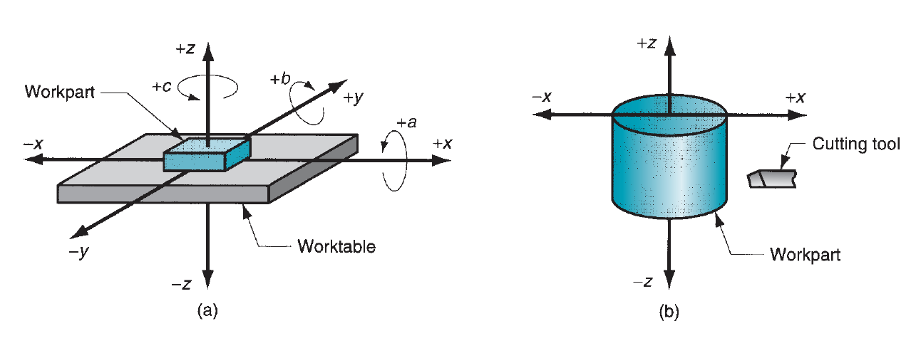
Figure 18: Coordinate systems used in numerical control: (a) for flat and prismatic work, and (b) for rotational work.
These systems are related to turning operations on NC lathes. Though the work rotates, this is often not one of the controlled axes in a standard NC turning system. The cutting path of the tool relative to the rotating piece of work is outlined within the x-z plane, as shown in our figure. In several NC systems, the relative movements between the process tool and also the workpart are accomplished by fixing the part to a work table then dominant the positions and motions of the table relative to a stationary or semi stationary work head. Most machine tools and element insertion machines are supported this methodology of operation. In alternative systems, the workpart is control stationary and also the work head is rapt on 2 or 3 axes. Flame cutters, x-y plotters, and coordinate measure machines operate during this mode.
Motion control systems supported NC may be divided into 2 types: (1) point-to-point and (2) continuous path. Point-to-point systems additionally referred to as positioning systems, move the work head (or workpiece) to a programmed location with no regard for the trail taken to induce thereto location. Once the move is completed, some process action is accomplished by the work head at the placement, admire drilling or punching a hole. Thus, the program consists of a series of purpose locations at that operations are performed. Continuous path systems offer continuous coincident control of over one axis, therefore dominant the trail followed by the tool relative to the part. This permits the tool to perform a method whereas the axes are moving, facultative the system to come up with angular surfaces, two-dimensional curves, or three-dimensional contours within the workpart. This operational theme is needed in drafting machines, sure edge and turning operations, and flame cutting. In machining, continuous path control additionally goes by the name contouring. a very important side of continuous path motion is interpolation, that cares with hard the intermediate points on a path to be followed by the work head relative to the part. 2 common kinds of interpolation are linear and circular. Linear interpolation is employed for line methods, during which the part computer user specifies the coordinates of the start purpose and finish point of the line yet because the feed rate to be used. The interpolator then computes the travel speeds of the 2 or 3 axes that may accomplish the desired mechanical phenomenon. Circular interpolation permits the work head to follow a circular arc by specifying the coordinates of its starting and finish points beside either the middle or radius of the arc. The interpolator computes a series of little line segments that may approximate the arc at intervals an outlined tolerance.
Another side of motion control cares with whether or not the positions within the system are outlined fully or incrementally. In absolute positioning, the work head locations are forever outlined with reference to the origin of the axis system. In progressive positioning, consequent work head position is outlined relative to this location.
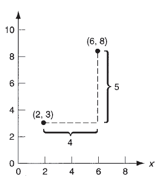
Figure 19: Absolute vs. incremental positioning. The work head is at point (2,3) and is to be moved to point (6,8). In absolute positioning, the move is specified by x=6, y=8; while in incremental positioning, the move is specified by x = 4, y = 5.
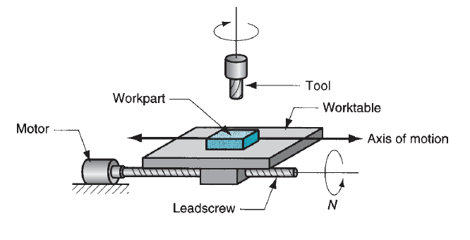
Figure 20: Motor and lead screw arrangement in an NC positioning system.