Unit 4
Joining/Fastening Processes
The process of joining two similar or dissimilar materials is referred as joining process. The joining process is referred as fastening process, when there is the use of fasteners to joint them.
The term ‘joining’ is mainly used for welding, brazing, soldering, and adhesive bonding that form a permanent or a temporary joint between the parts. Permanent joint is referred to a joint that cannot easily be separated while temporary joint is the joint that can be easily separated when required.
The joining process can be divided into a liquid state joining or a solid-state joining process.
These processes are primarily used for the assembly of the machine to join various parts either permanently or temporarily.
Joining process generally contains the processes like welding, brazing, soldering, fastening, adhesive bonding, etc.
Welding process is the most widely used process for a permanent joint. While fastening process is most widely used process for temporary joint.
Fastening process can be divided into three types:
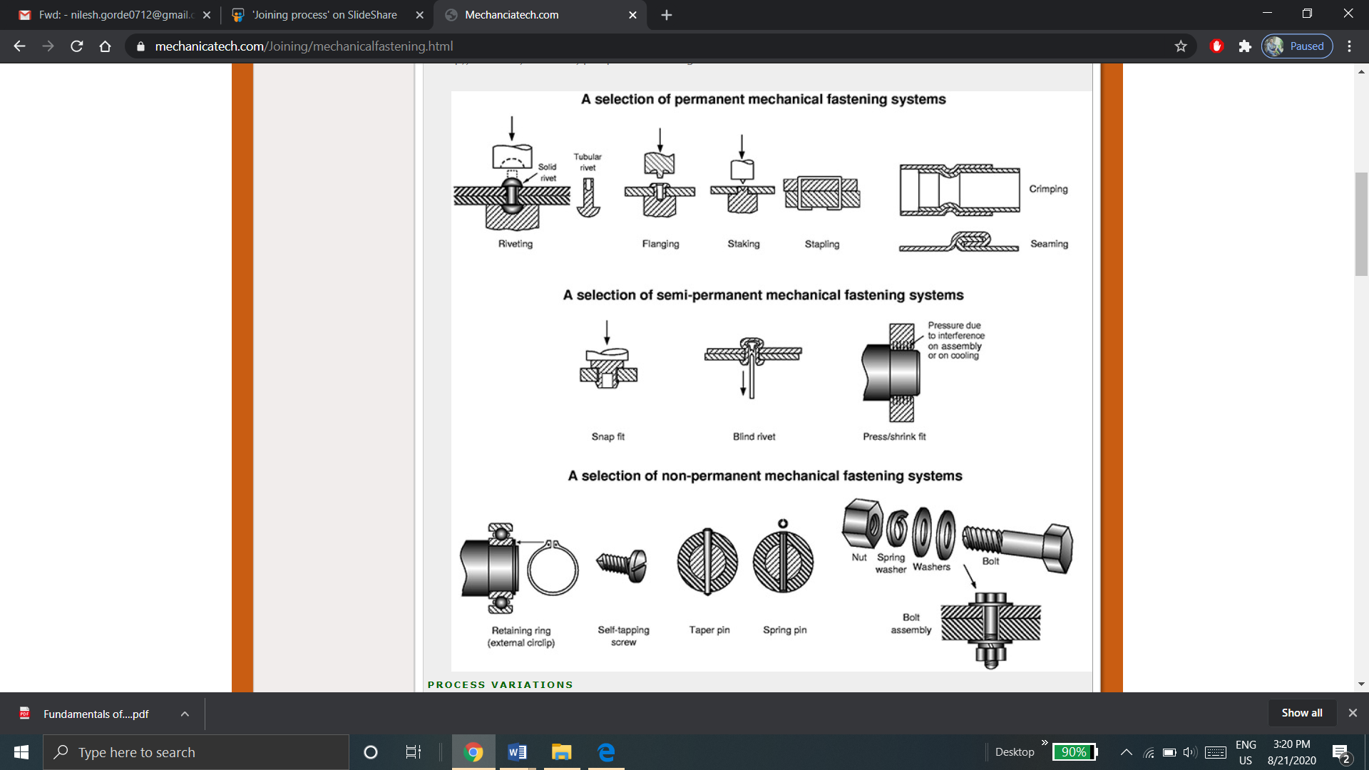
b. Semi-permanent fastening process: It includes snap fit, Blind rivet, press fit, etc.
c. Non-permanent fastening process: When the joint required is temporary, then non-permanent fastening process is used. It includes Retaining, self-tapping, nut-bolt assembly, etc.
Welding is referred a material joining process where two or more parts are joined at their contacting surfaces through appropriate application of heat and pressure. Most of the welding processes are achieved via means of heat alone or with pressure alone. In few welding processes, filler material is introduced to facilitate bonding. The assemblage of elements which are joined by welding is known as weldment. Welding is most commonly related to metal parts, whereas the process is additionally used for joining plastics.
Advantages of welding:
Limitations of welding:
Welding processes are divided into two major groups:
(1) fusion welding (liquid-state welding) and (2) solid-state welding.
Fusion Welding Process:
Fusion-welding processes make use of heat to melt the parent metals. In most of fusion welding operations, a filler metal is introduced to accelerate the process and offer strength to the welded joint. When there is no filler metal added, in a fusion-welding operation, is termed as an autogenous weld. The fusion category contains the most globally used welding processes that can be divided into the following types:
Solid State Welding Process:
Solid-state welding is a joining processes where joint results through application of pressure alone or by a mixture of heat and pressure. If heat is used for welding, the temperature in the operation is below the melting point of the metals that are being welded. There is no use of filler metal in solid state welding. Solid state welding is categorized into following types:
Physics of Welding:
Many bonding mechanisms are available for welding, but fusion welding is the most widely used welding operation.
In order to achieve fusion, high density of heat energy source is applied on the saying surfaces. The leading temperatures are enough to cause local melting of the parent metals. The heat density should be sufficient enough to melt the filler material, if added.
Heat density can be referred as power transferred to the work per unit of the surface area.
Power density is given by,

Where,
P is the power entering the surface.
A is the surface area in which power is entering
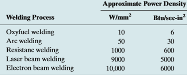
The time required to melt the metal is inversely proportional to the power density. The minimum power density require to melt the metal in general welding processes is found to be 10 W/mm2
The approximate power densities required for different welding processes is given in the table below:
The quantity of heat needed to melt a given volume of metal is dependent on the following factors:
The unit energy for melting ( ) is defined as the quantity of heat required to melt a unit volume of metal that starts from room temperature.
It is given by,

Where,
 is the melting point of an metal in kelvin
K is the constant with value; K = 3.33 x 10⁻⁶
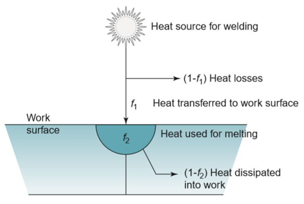
All this energy that is associated with heat source is not used to melt the metal. Some amount of heat is lost during the transfer of heat from source and to the workpiece, while some amount of heat is lost by dissipating heat into the work metal. This is shown in the figure below:
Heat transfer factor is defined as the ratio of the original heat received by the workpiece to the total heat generated at the source. It is denoted by  .
.
Melting factor is defined as the heat used for welding to the heat received at the workpiece. It is denoted by  .
.
Hence, heat available at welding is given by,

Where,
 is the net heat available for welding process
H is total heat generated at the source of heat.
The balance equation which gives relation between energy input and energy required for welding is

Where, V is the volume of metal melted.
If an assembly is to be permanently welded, the following guidelines should be followed by designer
The following design considerations apply to arc welding:

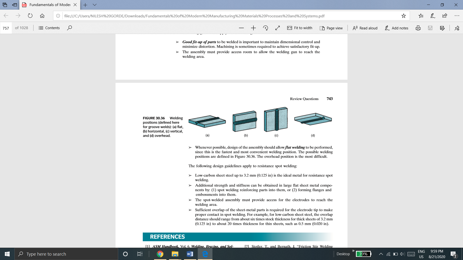
Figure Welding positions (defined here for groove welds): (a) flat, (b) horizontal, (c) vertical, and (d) overhead.
The following design guidelines apply to resistance spot welding:
Solid and liquid state joining process is referred to the joining process in which filler metal is melted or is in liquid state and is used for to create a bond between two solid metals.
Three different processes which are brazing, soldering and adhesive bonding are included in solid and liquid state joining process. The physical phenomenon associated with each of these processes is same but differ only in the metallurgical aspect. In these processes, the bulk material is not melted. A molten filler metal is used to provide a joint. The working temperature of these process is generally below the melting point of the base or parent metal.
Brazing
Brazing is a joining process where a filler metal is melted and disbursed through a capillary action among the two surfaces of the metal parts to be joined. Here, the distance between two mating surfaces is very less. Melting of the base metals doesn’t occur in brazing. In brazing only the filler material is melted. In brazing the filler metal (also called the brazing metal), has a melting temperature that is above 450oC but below the melting point of the base metals to be joined. The brazed joint is much stronger compared to the filler metal from which it has been created upon solidification. This is because of the less part clearances used in brazing. The other reasons for stronger brazed bond is the metallurgical bonding that takes place among base and filler metals as well as the geometric constrictions which are imposed at the joint via base parts.
Advantages of Brazing
Limitation of Brazing:
Soldering
Soldering is similar to brazing and can be defined as a joining process in which a filler metal, with melting point below 450oC, is melted and disbursed through capillary action among two surfaces of the metal parts to be joined. Similar to brazing, melting of the parent metals doesn’t occur but the filler metal is melted and it combines with the parent metal creating a metallurgical bond. Surfaces to be soldered should be pre-cleaned. This is done such that they are free of oxides, oils, etc. Proper flux should be applied to the soldering surfaces when the surfaces are heated. Filler metal, known as solder is added to the joint that disburses itself within the closely fitting parts of two materials. In industry, soldering is very closely connected to the electronics assembly.
Advantages of soldering:
Limitations of soldering:
Adhesive Bonding
Adhesive bonding is referred to a joining process where a filler material is used to hold two or more than two closely spaced parts together via means of a surface attachment. The filler material which helps in binding of these parts together is the referred to as adhesive. Adhesive is a nonmetallic substance, generally a polymer. Adherends are the parts that are being joined together.
A large number of commercially available adhesives are cured by various mechanisms and are suited to the bonding of various materials. Curing is defined as the process where the physical properties of adhesive are changed from a liquid to a solid, generally by chemical reaction, to achieve the surface attachment of the parts. The chemical reaction involves polymerization, condensation, or vulcanization. Curing is often motivated by heat or a catalyst, and pressure is sometimes applied between the two parts to activate the bonding process. If heat is required, the curing temperatures are relatively low, and so the materials being joined are usually unaffected. The curing or hardening of the adhesive requires time, called curing time or setting time. In some cases, setting time is generally significant.
Joint strength in adhesive bonding is determined by the strength of the adhesive itself and the strength of attachment between adhesive and each of the adherends.
Following are the conditions for adhesive bonding
The brazing and soldering processes are carried out by allowing a molten filler material to flow in the gap between the parent bodies.
To produce the perfect joint, the entire gap between the parent bodies must be filled by the filler material. This is achieved through the capillary action.
The theory of capillary flow tells us
In fact, the optimum gap maintained, between the parts to be joined is of 0.1 mm.
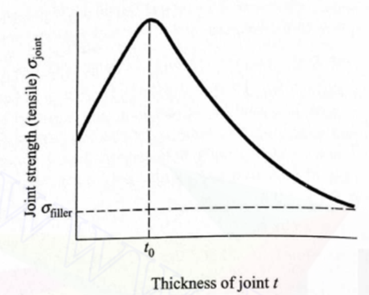
The strength of typically brazed joint varies with thickness of joint in the manner as show in figure below.

Variation of strength of brazed joint with joint thickness
From the figure it can be seen that optimum joint thickness  exists at which the strength is maximum. For the very large thickness of joint the strength of joint approaches to that of brazing alloy
It can be seen that, maximum joint strength is higher than the filler material. This is because the yield strength of the filer material is lower than the parent material.
Consider the joint be subjected to a tensile load of  . With increasing value of
  the filler material tends to yield as shown in figure:
The resulting deformation is shown in fig b.
The yield strength of a filler alloy is determined by uniaxial test, when the deformed shape of rectangular specimen ABCD takes the shape A’B’C’D’ (shown in fig c). If AD and BC are considered as the P-F interfaces, then in the presence of the parent material, the deformed shape of the same specimen takes the shape A’’B’’C’’D’’.
The deformed shape A’’B’’C’’D’’ can be obtained from ABCD by simultaneous application of constant tensile stress  on the faces AD and BC, together with the application of varying lateral tensile stress
  on the faces AB and CD. The magnitude of lateral stress
  is maximum at A and B with minimum of
  occurring at the midpoint of AB.
Now, as  is increased, the joint fails at the midpoint of AB. Using the maximum shear stress theory, we find the joint fails if

or the strength of the joint

Above equation clearly shows that,  is greater than
  . As the joint thickness increases,
  tends to zero and
  approaches the value of
Additive manufacturing process:
In additive manufacturing process, the object is manufactured by deposition of layers of material. In additive manufacturing, virtually there is no wastage of material.
Rapid Prototyping
Rapid Prototyping Technology is a set of manufacturing processes which allows the direct physical cognizance of 3D computer models.
This technology transfers the 3D computer data offered via a dedicated file format directly to a physical model that too layer by layer with a huge degree of accuracy.
Rapid prototyping is nothing but an additive process. This process combines layers of paper, wax, or plastic to generate a solid object. In contrast to many machining processes which are subtractive processes that remove material from a solid block.
Construction of physical model is done automatically from CAD data in RPT.
Fundamentals of Rapid Prototyping
The Rapid Prototyping Wheel depicting the 4 major aspects of RP

b. Method
The method employed by all vendors can be generally categorized into the following types:
• cutting and gluing or joining,
• photo-curing,
• melting and solidifying or fusing and joining or binding.
Photo-curing can be further divided into categories of
• single laser beam,
• masked lamp
• double laser beams and
c. Material
d. Application
• Design
• Engineering, Analysis and Planning
• Tooling and Manufacturing
Basic Steps in Rapid Prototyping Process
i) CAD Model Creation:
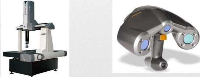
ii) Conversion to STL Format:
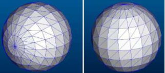
iii) Slice the STL File:
iv) Layer by Layer Construction:
v) Clean and Finish:
Classification of Rapid Prototyping
Based on initial form of material used, the rapid prototyping systems are broadly classified into three categories.
a) LIQUID-BASED
a) Stereolithography (SLA)
b) Polyjet Modelling
b) SOLID-BASED
a) Fused Deposition Modelling (FDM)
b) Laminated Object Modelling (LOM)
c) POWDER-BASED
a) Selective Laser Sintering (SLS)
b) 3D- Printing
Rapid-prototyping techniques have made possible much faster product development times, and they are having a major effect on other manufacturing processes. When proper materials are being used, rapid-prototyping machinery can create blanks for investment casting or similar processes. Hence that metallic parts may now be received fastly and economically, even for lot sizes as little as one part.
Such techniques also can be applied to create molds for operations (like injection molding, sand and shell mold casting, and also forging), thereby significantly reducing the lead time between design and manufacture.
Many approaches have been devised for the fast production of tooling (RT) via means of rapid-prototyping processes.
Rapid tooling is the process of manufacturing the tools using the rapid prototyping technique. It is widely used in many areas of industries.
The advantages to rapid tooling include the following:
The principal shortcoming of RT is the potentially decreased tool or pattern life as compared to the ones acquired from machined tool and die materials, like tool steels or tungsten carbides.
The easiest method of making use of rapid-prototyping operations to different manufacturing processes is in the direct generation of patterns or molds.
Classification of Rapid Tooling:
A] Classification method of tooling:
a. Direct Tooling
Direct Tooling is a process of making the tool, die or mold directly from the CAD data, using rapid prototyping process. For example, in injection molding, the main cavity, cores, runner, ejection system, etc. can be produced directly using rapid prototyping process.
b. Indirect Tooling
Indirect tooling is the process of making the master patterns for making tool, die or mold from CAD data, using rapid prototyping process.
It is not a tool production process but is a pre-production process. SLA, which gives a good accuracy and surface finish, is used as indirect tooling process.
B] Classification based on Material used:
a. Hard Tooling
Hard tooling is the process of making the tool, die or mold from hard materials like steel, using rapid prototyping process.
b. Soft Tooling
Soft tooling is the process of making the tool, die or mold from soft materials like silicon rubber, epoxy resin, low melting point alloys, etc. using rapid prototyping process.
Conventional Tooling vs Rapid Tooling:
RT is distinguished from conventional tooling in that,
Need of Rapid Tooling (RT)