Unit 5
Machine Tools
Lathes typically are thought-about to be the oldest machine tools. Though carpentry lathes originally were developed throughout the amount from a thousand to one B.C., formation lathes with lead screws weren't designed till the late 1700s. The foremost common lathe originally was known as engine lathe; as a result of it had been hopped-up with overhead pulleys and belts from close engines on the works floor. Modern lathes are all equipped with individual electrical motors. The most spindle speed of lathes generally is around 4000 revolutions per minute, however perhaps solely regarding two hundred revolutions per minute for giant lathes. For special applications, speeds could vary to 10000 rpm, 40000 rpm, or higher for terribly high speed machining. The price of lathes ranges from regarding $2,000 for bench varieties to over $100,000 for larger units.
Though easy and versatile, engine lathe needs a talented craftsman, as a result of all controls are manipulated by hand. Consequently, lathes are inefficient for repetitive operations and for giant production runs. The remainder of this section can describe the varied forms of automation that typically are side to enhance potency.
5.1.1 Lathe parts:
Lathes are equipped with a spread of components and accessories, their options and functions are as follows:
Bed: The bed supports all major parts of the lathe. Beds have an outsized mass and are designed stiffly, sometimes from grey or nodular forged iron. The highest portion of the bed has 2 ways that with varied cross sections that are hardened and machined for wear resistance and dimensional accuracy throughout turning. In gap-bed lathes, a locality of the bed before of the support is removed to accommodate larger diameter workpiece.
Carriage: The carriage, or carriage assembly, slides on the ways that consists of an assembly of the cross-slide, tool post, and apron. The cutting implement is mounted on the tool post, sometimes with a compound rest that swivels for tool positioning and adjustment. The cross-slide moves radially in and out, dominant the radial position of the cutting implement in operations comparable to facing. The apron is supplied with mechanisms for each manual and mechanized movement of the carriage and also the cross-slide by suggests that of the lead screw.
Headstock: The support is mounted to the bed and is supplied with motors, pulleys, and V-belts that offer power to a spindle at varied motility speeds. The speeds are set through manually controlled selectors or by electrical controls. Most headstocks are equipped with a group of gears, and a few have varied drives to supply a unceasingly variable vary of speed to the spindle. Headstocks have a hollow spindle to that work-holding devices (such as c/nicks and collets; are mounted and long bars or tube is fed through them for varied turning operations. The accuracy of the spindle is vital for exactitude in turning, notably in high-speed machining; preloaded tapered or ball bearings generally are accustomed stiffly support the spindle.
Tailstock: The support, which might slide on the ways that and be clamped at any position, supports the opposite finish of the piece of work. It’s equipped with a middle that will be mounted (dead center), or it's going to be unengaged to rotate with the piece of work (live center). Drills and reamers is mounted on the support quill (a hollow cylindrical dispense with a tapered hole) to drill axial holes within the piece of work.
Feed Rod and Lead Screw: The feed rod is hopped-up by a group of gears through the support. The rod rotates throughout the lathe operation and provides movement to the carriage and also the cross-slide by suggests that of gears, a clutch, and a keyway on the length of the rod. Closing a split nut round the lead screw engages it with the carriage; the split nut is additionally used for cutting threads accurately.
5.1.2 Lathe Workholding Devices and Tool Layout:
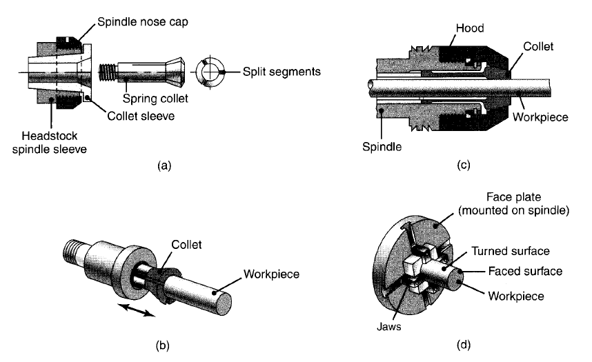
Figure 1: (a) and (b) Schematic illustrations of a draw-in type of collet. The workpiece is placed in the collet hole, and the conical surfaces of the collet are forced inward by pulling it with a draw bar into the sleeve. (c) A push-out type of collet. (d) Work holding of a workpiece on a face plate.
Workholding devices are vital, notably in machine tools and machining operations, as they need to hold the piece of work firmly. One end of the piece of work is clamped to the spindle of the lathe by a chuck, collet, face plate or mandrel. A chuck sometimes is supplied with 3 or four jaws. Three-jaw chucks typically have a geared-scroll style that creates the jaws self-centering. they're used for spherical workpiece (such as bar stock, pipes, and tubing), which might be targeted to inside zero.025 mm. Four-jaw (independent) chucks have jaws which will be affected and adjusted severally of every alternative. Thus, they'll be used for sq., rectangular, or odd-shaped workpiece. As a result of this they are created additional ruggedly than three jaw chucks; four-jaw chucks are used for significant workpiece or for work requiring multiple chucking’s wherever disk shape is vital. The jaws in some forms of chucks is reversed to allow clamping of hollow workpiece, comparable to pipes and tube, either on the skin surfaces or on the within surfaces. Conjointly obtainable are jaws manufactured from soft-cast steel (soft jaws) which will be machined into desired shapes. As a result of their low strength and hardness, soft jaws change to little irregularities on workpiece and so end in higher clamping. Chucks is power or manually motivated with a chuck wrench. As a result of they take longer to work, manually motivated chucks typically are used just for tool room and restricted production runs. Power chucks, motivated pneumatically or hydraulically, are utilized in machine-controlled instrumentation for prime production rates, as well as the loading of components victimization industrial robots. conjointly obtainable are many forms of power chucks with lever- or wedge-type mechanisms to actuate the jaws; these chucks have jaw movements (stroke) that typically are restricted to regarding thirteen millimeter.
Chucks are obtainable in varied styles and sizes. Their choice depends on the sort and speed of operation, piece of work size, production and dimensional accuracy necessities, and also the jaw forces needed. By dominant the magnitude of the jaw forces, operator will make sure that the half doesn't supply the chuck throughout machining. High spindle speeds will scale back jaw (clamping) forces considerably thanks to the result of centrifugal forces; this effect is especially vital in exactitude tube turning. Modern jaw-actuating mechanisms allow a better clamping force for roughing, and lower force for finishing, operations.

Figure 2: Various types of mandrels to hold workpieces for turning. These mandrels usually are mounted between centers on a lathe. Note that in (a) both the cylindrical and the end faces of the workpiece can be machined, whereas in (b) and (c) only the cylindrical surfaces can be machined.
A collet is essentially a longitudinally-split, tapered bushing. The piece of work (generally with a most diameter of twenty five mm) is placed within the collet, and also the collet is force or pushed automatically into the spindle. The tapered surfaces shrink the segments of the collet radially, adjustment onto the piece of work. Collets are used for spherical workpiece as well as for alternative shapes (e.g., sq. or polygonal shape work pieces) and are obtainable in an exceedingly wide selection of sizes. One advantage to employing a collet (rather than a three- or four-jaw chuck) is that the collet grips nearly the complete circumference of the part, creating the device well suited notably for components with little cross sections. As a result of the radial movement of the collet segments is little, work pieces typically ought to be inside 0.125 millimeter of the nominal size of the collet. Face plates are used for clamping on an irregular basis formed workpieces. The plates are spherical and have many slots and holes through that the piece of work is locked or clamped. Mandrels are placed within hollow or hollow workpieces and are accustomed hold workpieces that need machining on each ends or on their cylindrical surfaces. Some mandrels are mounted between centers on the lathe.
Accessories: Many devices are obtainable as accessories and attachments for lathes. Among these devices are the following:
5.1.3 Lathe Operations:
In an exceedingly typical turning operation, the piece of work is clamped by anybody of the workholding devices delineate antecedently. Long and slender components should be supported by a gradual rest and follow rest placed on the bed, as otherwise the half can deflect below the cutting forces. These rests sometimes are equipped with 3 adjustable fingers or rollers that support the piece of work whereas permitting it to rotate freely. Steady rests are clamped directly on the ways that of the lathe whereas follow rests are clamped on the carriage and travel with it. The cutting implement is connected to the tool post that is driven by the lead screw. The cutting implement removes material by traveling on the bed. A right-hand tool travels toward the support, and a left-hand tool travels toward the support. Facing operations are done by moving the tool radially with the cross-slide and conjointly clamping the carriage for higher dimensional accuracy.
Form tools are accustomed turn out varied shapes on solid, spherical workpieces by moving the tool radially inward whereas the half is rotating. Type cutting isn't appropriate for deep and slim grooves or sharp corners, as a result of vibration and chatter could result and cause poor surface end. As a rule, (a) the shaped length of the half shouldn't be larger than regarding 2.5 times the minimum diameter of the half, (b) the cutting speed ought to be set properly, and (c) cutting fluids ought to be used. The stiffness’s of the machine tools and work-holding devices are vital concerns.
Boring on a lathe is comparable to turning. It’s performed within hollow workpieces or in an exceedingly hole created antecedently by drilling or alternative suggests that. Out-of-shape holes are straightened by boring. The piece of work is control in an exceedingly chuck or in another appropriate work-holding device. Drilling is performed on a lathe by mounting the drilling bit in an exceedingly chuck within the support quill. The piece of work is clamped in an exceedingly work holder on the support, and also the drilling bit is advanced by rotating the hand wheel of the support. Holes drilled in this manner might not be sufficiently coaxial as a result of the tendency for the drill to drift radially. The concentricity of the outlet is improved by afterward boring the drilled hole. Drilled holes is also reamed on lathes in an exceedingly manner like drilling, so rising hole dimensional tolerances and surface end.
The tools for parting, grooving, thread cutting, and varied alternative operations are specially formed for his or her specific purpose or are obtainable as inserts. Knurling is performed on a lathe with hardened rolls, during which the surface of the rolls could be a reproduction of the profile to be generated. The rolls are ironed radially against the rotating piece of work whereas the tool moves axially on the part.
5.1.4 Forms of Lathes:
There are varieties of alternative lathe varieties, temporary descriptions of that are given here.
Bench Lathes: Because the name suggests, these lathes are placed on a bench or a table. They need low power, are sometimes operated by hand feed, and are accustomed machine little workpieces. Toolroom lathes have high exactitude, enables the machining of components to shut dimensional tolerances.
Special-purpose Lathes: These lathes are used for applications (such as railroad wheels, gun barrels, and rolling-mill rolls) with piece of work sizes as giant as 1.7 m in diameter by eight m long and capacities of 450 kilowatt
Tracer Lathes: These lathes have special attachments that are capable of turning components with varied contours. Conjointly known as a duplicating lathe or contouring lathe, the cutting implement follows a path that duplicates the contour of a template, like a pencil following the form of a plastic stencil. However, operations generally performed on a tracer lathe are replaced mostly by numerical-control lathes and turning centers.
Automatic Lathes: Lathes became more and more machine-controlled over the years; manual machine controls are replaced by varied mechanisms that modify machining operations to follow a definite prescribed sequence. in an exceedingly absolutely automatic lathe, components are fed and removed mechanically, whereas in semi-automatic machines, these functions are performed by the operator. (The cutting remains automatic.) Automatic lathes could have a horizontal or vertical spindle and are appropriate for medium- to high-volume production. Lathes that don't have tailstocks are known as chucking machines or chuckers. They used for machining individual items of normal or irregular shapes and are either single- or multiple-spindle varieties. In another kind of automatic lathe, the bar stock is fed sporadically into the lathe and an area is machined and discontinue from the top of the bar stock.
Automatic Bar Machines: Conjointly known as automatic screw machines, these machine tools are designed for high-production-rate machining of screws and similar rib components. All operations on these machines are performed mechanically with tools connected to a special turret. When every half or screw is machined to finished dimensions, the bar stock is fed forward mechanically through the outlet within the spindle then discontinue. Automatic bar machines are also equipped with single or multiple spindles. Capacities vary from 3- to 150-mm diameter bar stock. Long stock is supported by special fixtures because it enters the spindle hole.
Single-spindle automatic bar machines are like turret lathes and are equipped with varied cam-operated mechanisms. There are 2 forms of single spindle machines. In Swiss-type-automatic the cylindrical surface of the solid-bar stock is machined with a series of tools that move radially and within the same plane toward the piece of work. The bar stock is clamped near to the support spindle, that minimizes deflections thanks to cutting forces. These machine tools are capable of high-precision machining of small-diameter components. The opposite single-spindle machine (called the American type) is comparable to a tiny low automatic turret lathe. The turret is on a vertical plane, and every one motions of the machine parts are controlled by cams. Automatic bar machines are currently equipped with laptop numerical management, eliminating the employment of cams, and also the operation is programmed for a selected product.
Multiple-spindle automatic bar machines generally have from four to eight spindles organized in an exceedingly circle on an outsized drum, with every carrying a personal piece of work. The cutting tools are organized in varied positions within the machine and move in each axial and radial direction. Every half is machined little by little because it moves from one station to successive. As a result of all operations is meted out at the same time, the cycle time per half is reduced.
Turret Lathes: These machine tools are capable of activity multiple cutting operations, comparable to turning, boring, drilling, thread cutting, and facing. Many cutting tools (usually as several as six) are mounted on the polygonal shape main turret, that is turned when every specific cutting operation is completed. The lathe sometimes includes a sq. turret on the cross-slide, mounting as several as four cutting tools. The piece of work (generally an extended, spherical bar stock) is advanced a planned distance through the chuck. When the half is machined, it does discontinue by a tool mounted on the sq. turret that moves radially into the piece of work. The rod then is advanced identical planned distance, and also the next half is machined. Turret lathes (either the bar kind or the chucking type) are versatile, and also the operations is also meted out either by hand, victimization the gate (capstan wheel), or mechanically. Once found out properly, these machines don't need extremely experienced operators.
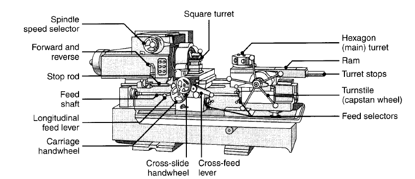
Figure 3: Schematic illustration of the components of a turret lathe. Note the two turrets: square and hexagonal (main).
Vertical turret lathes are available; they're additional appropriate for brief, significant workpieces with diameters as giant as 1.2 m. The turret lathe shown in figure is understood as a ram-type turret lathe-one during which the ram slides in an exceedingly separate base on the saddle. The short stroke of the turret slide limits this machine to comparatively short workpieces and lightweight cuts in each small- and medium-quantity production. In another vogue (called the saddle type), the most turret is put in directly on the saddle, that slides on the bed. The length of the stroke is proscribed solely by the length of the bed. This kind of lathe is made additional heavily and is employed to machine giant workpieces. As a result of the significant weight of the parts, saddle-type lathe operations are slower than ram type operations.
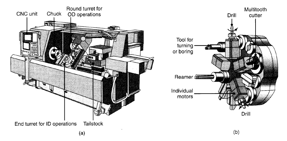
Figure 4: (a) A computer-numerical-control lathe. Note the two turrets. These machines have higher power and spindle speed than other lathes in order to take advantage of new cutting tools with enhanced properties. (b) A typical turret equipped with 10 tools, some of which are powered.
Computer-controlled Lathes: Within the most advanced lathes, movement and management of the machine and its parts are achieved by laptop numerical control (CNC). These lathes typically are equipped with one or additional turrets and every turret are supplied with a spread of tools and perform many operations on totally different surfaces of the piece of work. Workpiece diameters is also the maximum amount as one m. to require advantage of latest cutting-tool materials, computer-controlled lathes are designed to work quicker and have higher power obtainable compared with alternative lathes. They’re equipped with automatic tool changers (ATCs). Their operations are faithfully repetitive, maintain the required dimensional accuracy, and need less experienced labor (once the machine is about up). They’re appropriate for low- to medium volume production.
Milling could be a machining operation during which a workpart is fed past a rotating cylindrical tool with multiple cutting edges. (In rare cases, a tool with one leading edge, known as a fly-cutter, is used). The axis of rotation of the cutting implement is perpendicular to the direction of feed. This orientation between the tool axis and also the feed direction is one among the options that distinguishes edge from drilling. In drilling, the cutting implement is fed in an exceedingly direction parallel to its axis of rotation. The cutting implement in edge is termed a milling cutter and also the cutting edges are called teeth. The standard machine that performs this operation could be a lathe. The reader will read milling operations and also the varied milling machines in our video clip on milling and machining centers. The geometric type created by edge could be a plane surface. Alternative work geometries is created either by suggests that of the cutter path or the cutter form. Due to the range of shapes attainable and its high production rates, milling is one among the foremost versatile and wide used machining operations. Milling is interrupted cutting operation; the teeth of the milling cutter enter and exit the work throughout every revolution. This interrupted cutting action subjects the teeth to a cycle of impact force and thermal shock on each rotation. The tool material and cutter geometry should be designed to face up to these conditions.
5.2.1 Forms of Milling Operations:
There are 2 basic types of milling operations:
(a) Peripheral milling and
(b) Face milling.
Most milling operations produce geometry by generating the form.
Peripheral milling: In peripheral milling, conjointly known as plain milling, the axis of the tool is parallel to the surface being machined, and also the operation is performed by cutting edge on the skin fringe of the cutter. (a) slab milling, the fundamental kind of peripheral milling during which the cutter dimension extends on the far side the piece of work on each sides; (b) slotting, conjointly known as slot milling, during which the dimension of the cutter is a smaller amount than the piece of work width, making a extract the work - when the cutter is incredibly skinny, this operation is accustomed mill slim slots or cut a workpart in 2, known as saw milling; (c) side milling, during which the cutter machines the facet of the workpiece; (d) straddle milling, identical as facet milling, solely cutting takes place on each side of the work; and form milling, during which the milling teeth have a special profile that determines the form of the slot that's cut within the work. Form milling is so classified as a forming operation. In peripheral milling, the direction of cutter rotation distinguishes 2 varieties of milling: up milling and down milling.
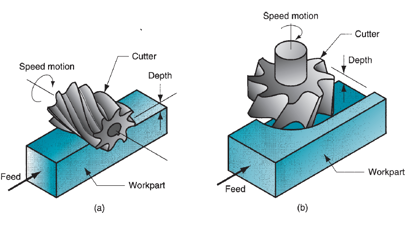
Figure 5: Two basic types of milling operations: (a) peripheral or plain milling and (b) face milling.
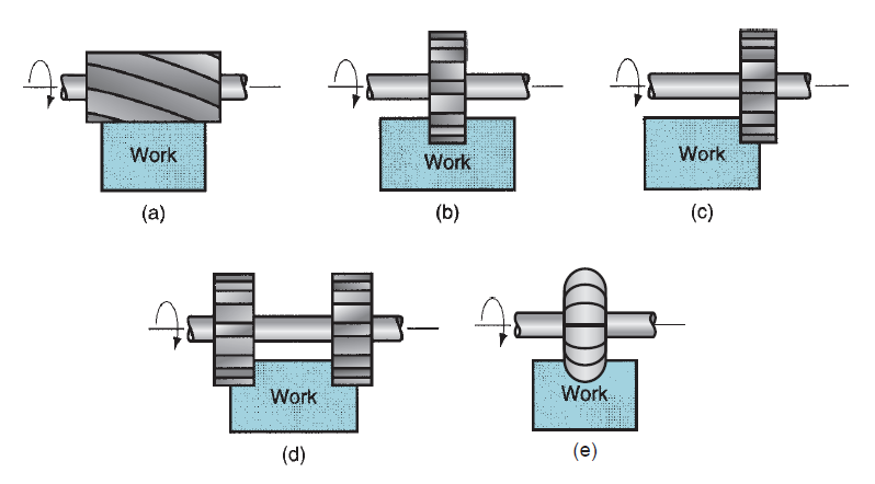
Figure 6: Peripheral milling: (a) slab milling, (b)slotting, (c) side milling, (d) straddle milling, and (e) form milling.
In up milling, conjointly known as typical milling, the direction of motion of the cutter teeth is opposite the feed direction once the teeth remove the work. It is milling ‘‘against the feed.’’ In down milling, conjointly known as climb milling, the direction of cutter motion is that the same because the feed direction once the teeth cut the work. This is milling ‘‘with the feed.’’ The relative geometries of those 2 varieties of milling end in variations in their cutting actions. In up milling, the chip shaped by every cutter tooth starts out terribly skinny and will increase in thickness throughout the sweep of the cutter. In down milling, every chip starts out thick and reduces in thickness throughout the cut. The length of a kick in down milling is a smaller amount than in up milling (the distinction is exaggerated in our figure). This suggests that the cutter is engaged within the work for fewer times per volume of fabric cut, and this tends to extend tool life in down milling. The cutting force direction is tangential to the fringe of the cutter for the teeth that are engaged within the work. In up milling, this includes a tendency to elevate the workpart because the cutter teeth exit the fabric. In down milling, this cutter force direction is downward, tending to carry the work against the lathe table.
Face milling: In face milling, the axis of the cutter is perpendicular to the surface being processed, and machining is performed by cutting edges on each the top and outdoors fringe of the cutter.
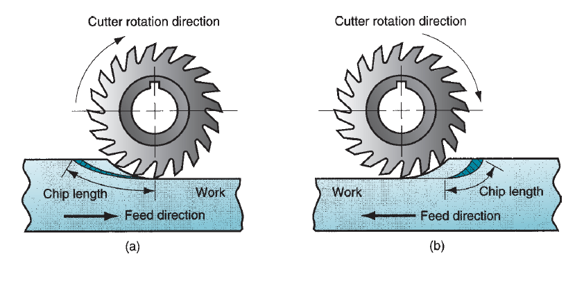
Figure 7: Two forms of peripheral milling operation with a 20-teeth cutter: (a) up milling, and (b) down milling.
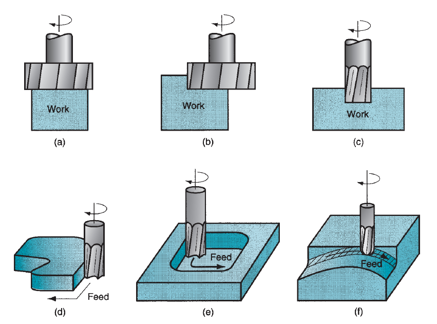
Figure 8: Face milling: (a) conventional face milling, (b) partial face milling, (c) end milling, (d) profile milling, (e) pocket milling, and (f) surface contouring.
As in peripheral milling, varied varieties of face milling exist, (a) typical face milling, during which the diameter of the cutter is larger than the workpart dimension, therefore the cutter overhangs the work on each sides; (b) partial face milling, wherever the cutter overhangs the work on only 1 side; (c) finish milling, during which the cutter diameter is a smaller amount than the work dimension, thus a slot is remove the part; (d) profile milling, a kind of finish milling during which the skin fringe of a flat half is cut; (e) pocket milling, another kind of finish milling accustomed mill shallow pockets into flat parts; and (f) surface contouring, during which a ball-nose cutter (rather than square-end cutter) is fed back and forth across the work on a curvilinear path at shut intervals to create a three dimensional surface form. Identical basic cutter management is needed to machine the contours of mildew and die cavities, during which case the operation is termed die sinking.
5.2.2 Cutting Conditions in Milling:
The cutting speed is decided at the skin diameter of a milling cutter. this could be regenerate to spindle rotation speed employing a formula that ought to currently be familiar:

The feed f in milling is usually given as a feed per cutter tooth; called the chip load, it represents the size of the chip shaped by every leading edge. This could be regenerate to feed rate by taking under consideration the spindle speed and also the range of teeth on the cutter as follows:

wherever fr = feed rate, mm/min(in/min);N = spindle speed, rev/min; nt = number of teeth on the cutter; and f = chip load in mm/tooth (in/tooth).
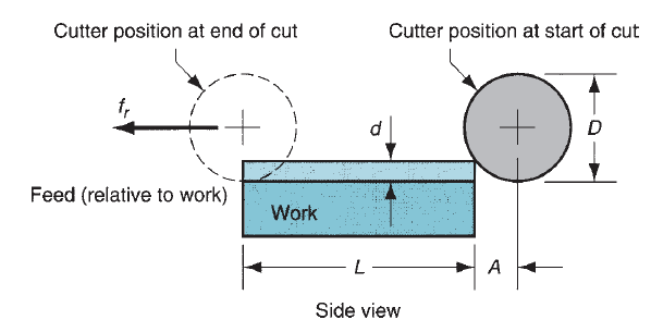
Figure 9: Slab (peripheral) milling showing entry of cutter into the workpiece.
Material removal rate in milling is decided victimization the merchandise of the cross-sectional space of the cut and also the feed rate. Consequently, if a slab-milling operation is cutting a piece of work with dimension w at a depth d, the fabric removal rate is

This neglects the initial entry of the cutter before full engagement. Above equation is applied to finish milling, facet milling, face milling, and alternative milling operations, creating the correct changes within the computation of cross-sectional space of cut. The time needed to mill a piece of work of length L should account for the approach distance required to totally interact the cutter. First, think about the case of block milling, Figure 22.21. to work out the time to perform a block milling operation, the approach distance A to succeed in full cutter depth is given by

wherever d = depth of cut, mm(in); and D = diameter of the milling cutter, mm(in). The time metallic element during which the cutter is engaged milling the piece of work is so

For face milling, allow us to think about the 2 attainable cases pictured in below figure. The first case is once the cutter is targeted over an oblong piece of work as in Figure (a). The cutter feeds from right to left across the workpiece. So as for the cutter to succeed in the complete dimension of the work, it should travel approach distance given by the following:

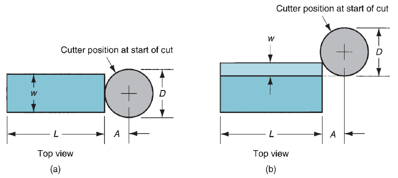
Figure 10: Face milling showing approach and over travel distances for two cases: (a) when cutter is centered over the workpiece, and (b) when cutter is offset to one side over the work.
Where D = cutter diameter, mm(in) and w = width of the workpiece, mm(in). If D = w, then equation reduces to A = 0.5D. And if D<w, then a slot is remove the work and A = 0.5D. The second case is when the cutter is offset to at least one facet of the work. During this case, the approach distance is given by

wherever w = dimension of the cut, mm (in). In either case, the machining time is given by

It ought to be emphasized all told of those milling eventualities that Tm represents the time the cutter teeth are engaged within the work, creating chips. Approach and over travel distances are sometimes side at the start and finish of each cut to allow access to the work for loading and unloading. so the particular period of the cutter feed motion is probably going to be larger than Tm.
5.2.3 Shaping and Planning:
Shaping and planning are similar operations, each involving the employment of a single-point cutting tool affected linearly relative to the workpart. In typical shaping and planning, a straight, flat surface is made by this action. In shaping, the speed motion is accomplished by moving the cutting tool; whereas in planning, the speed motion is accomplished by moving the workpart.
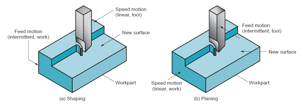
Figure 11: (a) Shaping, and (b) planning.
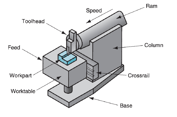
Figure 12: Components of a shaper.
Cutting tools utilized in shaping and planning are single-point tools. In contrast to turning, interrupted cutting happens in shaping and planning, subjecting the tool to a control loading upon entry into the work. Additionally, these machine tools are restricted to low speeds thanks to their start-and-stop motion. The conditions usually dictate use of tool steel cutting tools.
Shaping:
Shaping is performed on a machine known as a lathe. The parts of the lathe embody a ram that moves relative to a column to supply the cutting motion and a table that holds the half and accomplishes the feed motion. The motion of the ram consists of a forward stroke to realize the cut, and a come stroke throughout that the tool is upraised slightly to clear the work then reset for successive pass. On completion of every come stroke, the table is advanced laterally relative to the ram motion so as to feed the half. Feed is per mm/stroke (in/stroke). The drive mechanism for the ram is either hydraulic or mechanical. Hydraulic drive has larger flexibility in adjusting the stroke length and an additional uniform speed throughout the forward stroke; however it's dearer than a mechanical drive unit. Each mechanical and hydraulic drives are designed to realize higher speeds on the come (noncutting) stroke than on the forward (cutting) stroke, thereby increasing the proportion of your time spent cutting.
Planning:
The machine for planning could be a power tool. Cutting speed is achieved by a reciprocatory table that moves the half past the single-point cutting implement. The development and motion capability of a power tool allow abundant larger components to be machined than on a lathe. Planners are classified as open facet planers or double-column planers. The open-side power tool, conjointly called a single-column power tool, includes a single column supporting the cross-rail on that a tool head is mounted. Another tool head also can be mounted and fed on the vertical column. Multiple tool heads allow over one move be taken on every pass. At the completion of every stroke, every tool head is affected relative to the cross-rail (or column) to realize the intermittent feed motion. The configuration of the open-side power tool permits terribly wide workparts to be machined. A double-column power tool has 2 columns, one on either facet of the bottom and table. The columns support the cross-rail, on that one or additional tool heads are mounted. the 2 columns offer a more rigid structure for the operation; but, the 2 columns limit the dimension of the work which will be handled on this machine.
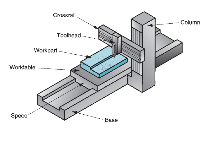
Figure 13: Open-side planer.

Figure 14: Types of shapes that can cut by shaping and planning: (a) V-groove, (b) square-groove, (c) T-slot, (d) dovetail slot, and (e) gear teeth.
Shaping and planning is accustomed machine shapes save for flat surfaces. The restriction is that the cut surface should be straight. This enables the cutting of grooves, slots, gear teeth, and alternative shapes. Special machines and gear geometries should be fixed to chop a number of these shapes. A vital example is that the gear lathe, a vertical lathe with a specially designed rotary feed table and synchronized tool head accustomed generate teeth on spur gears.
5.2.4 Milling Cutters:
The major varieties of milling cutters are the following:
Plain milling cutters: These are used for peripheral or slab milling. They’re cylinder formed with many rows of teeth. The cutting edges are sometimes homeward-bound at helix angle (as within the figures) to scale back impact on entry into the work and these cutters are referred to as helical milling cutters.
Form milling cutters: These are peripheral milling cutters during which the cutting edges have a special profile that's to be imparted to the work. A very important application is in gear making, during which the shape milling cutter is formed to chop the slots between adjacent gear teeth, thereby going the geometry of the gear teeth.
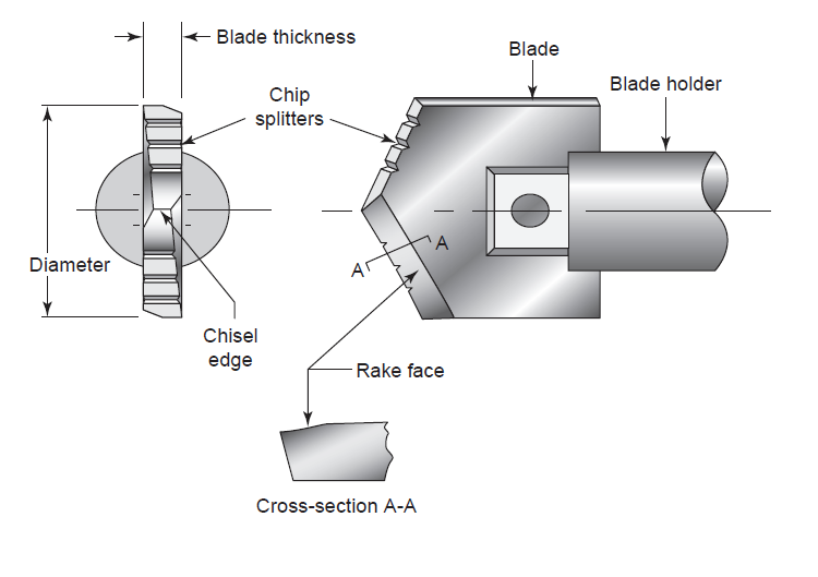
Figure 15: Spade drill.
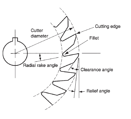
Figure 16: Tool geometry elements of an 18-tooth plain milling cutter.
Face milling cutters: These are designed with teeth that cut on each the periphery as well as the end of the cutter. Face milling cutters are often manufactured from HSS, or they will be designed to use cemented carbide inserts
End milling cutters: An end milling cutter feels like a drill bit, but shut examination indicates that it's designed for primary cutting with its peripheral teeth instead of its finish. (A drilling bit cuts solely on its end because it penetrates into the work.) End mills are designed with sq. ends, ends with radii, and ball ends. End mills are often used for face milling, profile milling and pocketing, cutting slots, engraving, surface contouring, and die sinking.
Drilling, could be a machining operation accustomed produce a round hole in an exceedingly workpart. This contrasts with boring, which might solely be accustomed enlarge an existing hole. Drilling is sometimes performed with a rotating cylindrical tool that has 2 cutting edges on its operating finish. The tool is termed a drill or drilling bit. The foremost common drilling bit is that the bit. The rotating drill feeds into the stationary workpart to make a hole whose diameter is adequate to the drill diameter. Drilling is usually performed on a drill press, though alternative machine tools conjointly perform this operation. The video clip on hole creating illustrates the drilling operation.
5.3.1 Operations Regarding Drilling:
Many operations are related to drilling. Most of the operations follow drilling; a hole should be created 1st by drilling, then the outlet is changed by one among the opposite operations. Centering and spot facing are exceptions to the present rule. All of the operations use rotating tools.
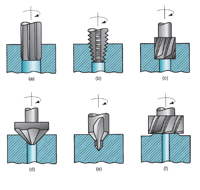
Figure 17: Machining operations related to drilling: (a) reaming, (b) tapping, (c) counterboring, (d) countersinking, (e) center drilling, and (f) spot facing.
(a) Reaming: Reaming is employed to slightly enlarge a hole, to supply a much better tolerance on its diameter, and to enhance its surface end. The tool is termed a reamer, and it always has straight flutes.
(b) Tapping: This operation is performed by a faucet is employed to supply internal screw threads on an existing hole.
(c) Counterboring: Counterboring provides a stepped hole, during which a bigger diameter follows a smaller diameter part into the outlet. A counterbored hole is employed to seat bolt heads into a hole therefore the heads don't protrude higher than the surface.
(d) Countersinking: This is often like counterboring, except that the step within the hole is cone like for flat head screws and bolts.
(e) Centering: Conjointly known as center drilling, this operation drills a beginning hole to accurately establish its location for ulterior drilling. The tool is termed a middle drill.
(f) Spot facing: Spot facing is comparable to milling. It’s accustomed offer a flat machined surface on the workpart in an exceedingly localized space.
Drilling tool geometry:
Drills varied cutting tools are obtainable for hole creating, however the twist drill is the foremost common. It comes in diameters starting from regarding 0.15 mm (0.006 in) to as giant as seventy five millimeter (3.0 in). Twist drills are wide utilized in business to supply holes speedily and economically. The quality twist drill geometry is illustrated in figure. The body of the drill has 2 spiral flutes (the spiral offers the twist drill its name). The angle of the spiral flutes is termed the angle, a typical worth of that is around 300. Whereas drilling, the flutes act as passageways for extraction of chips from the outlet. Though it's fascinating for the flute openings to be giant to supply most clearance for the chips, the body of the drill should be supported over its length. This support is provided by the net that is that the thickness of the drill between the flutes. The purpose of the twist drill includes a conical shape. A typical worth for the point angle is 1180.
The point is designed in varied ways that, however the foremost common style could be a chisel edge. Connected to the chisel edge are 2 cutting edges (sometimes known as lips) that lead into the flutes. The portion of every flute adjacent to the leading edge acts because the rake faces of the tool. The cutting action of the twist drill is advanced. The rotation and feeding of the drilling twist drill end in relative motion between the cutting edges and the workpiece to make the chips. The cutting speed on every leading edge varies as a operate of the space from the axis of rotation. Consequently, the potency of the cutting action varies, being most effective at the outer diameter of the drill and least efficient at the middle. In fact, the relative rate at the drill point is zero, thus no cutting takes place. Instead, the chisel fringe of the drill point pushes aside the fabric at the middle because it penetrates into the outlet; an outsized thrust force is needed to drive the twist drill forward into the hole. Also, at the start of the operation, the rotating chisel edge tends to wander on the surface of the workpart, inflicting loss of point accuracy. Varied various drill point styles are developed to handle this downside. Chip removal is a tangle in drilling. The cutting action takes place within the outlet, and also the flutes should offer sufficient clearance throughout the length of the drill to permit the chips to be extracted from the outlet. Because the chip is created it's forced through the flutes to the surface. Friction makes matters worse in 2 ways that. Additionally to the standard friction in metal cutting between the chip and also the rake face of the leading edge, friction conjointly results from rubbing between the skin diameter of the drilling twist drill and also the fresh shaped hole. This will increase the temperature of the drill and work. Delivery of cutting fluid to the drill point to scale back the friction and warmth is tough as a result of the chips are flowing within the wrong way. As a result of chip removal and warmth, a twist drill is often restricted to a hole depth of regarding fourfold its diameter. Some twist drills are designed with internal holes running their lengths, through that cutting fluid is pumped-up to the outlet close to the drill point, so delivering the fluid on to the cutting operation. An alternate approach with twist drills that don't have fluid holes is to use a ‘‘pecking’’ procedure throughout the drilling operation. During this procedure, the drill is sporadically withdrawn from the outlet to clear the chips before continuing deeper. Twist drills are usually manufactured from tool steel. The geometry of the drill is invented before heat treatment, and then the outer shell of the drill (cutting edges friction surfaces) is hardened whereas holding an inner core that's comparatively powerful. Grinding is employed to sharpen the cutting edges and form the drill point.
Grinding is a material removal method accomplished by abrasive particles that are contained during a secure grinding wheel rotating at terribly high surface speeds. The grinding wheel is usually disk-shaped, and is exactly balanced for prime movement speeds.
Grinding will be likened to the milling method. Cutting happens on either the periphery or the face of the emery wheel, like peripheral and face edge. Peripheral grinding is far additional common than face grinding. The rotating grinding wheel consists of the many cutting teeth (the abrasive particles), and therefore the work is fed relative to the wheel to accomplish material removal. Despite these similarities, there are significant differences between grinding and milling: (1) the abrasive grains within the wheel are abundant smaller and additional varied than the teeth on a milling cutter; (2) cutting speeds in grinding are abundant beyond in milling; (3) the abrasive grits during a emery wheel are randomly oriented and possess on the average a really high negative rake angle; and (4) a grinding wheel is self-sharpening - as the wheel wears, the abrasive particles become dull and either fracture to form contemporary cutting edges or are force out of the surface of the wheel to expose new grains.
5.4.1 The Grinding Wheel:
A grinding wheel consists of abrasive particles and bonding material. The bonding material holds the particles in situ and establishes the form and structure of the wheel. These two ingredients and the approach they're invented verify the 5 basic parameters of a grinding wheel: (1) abrasive material, (2) grain size, (3) bonding material, (4) wheel grade, and (5) wheel structure. To realize the required performance during a given application, each of the parameters should be fastidiously elite.
Abrasive Material: Totally different abrasive materials are applicable for grinding different work materials. General properties of associate degree abrasive material employed in grinding wheels include high hardness, wear resistance, toughness, and friability. Hardness, wear resistance, and toughness are fascinating properties of any cutting-tool material. Friability refers to the capacity of the abrasive material to fracture once the leading edge of the grain becomes dull, thereby exposing a replacement sharp edge. The development of grinding abrasives is represented in our historical note. Today, the abrasive materials of greatest industrial importance are corundum, silicon carbide, cubic element nitride, and diamond.
Grain Size: The grain size of the abrasive particle is vital in decisive surface finish and material removal rate. Tiny grit sizes turn out higher finishes, whereas larger grain sizes permit larger material removal rates. Thus, a choice must be made between these two objectives once choosing abrasive grain size. The choice of grit size additionally depends to some extent on the hardness of the work material. More durable work materials need smaller grain sizes to cut effectively, whereas softer materials need larger grit sizes. The grit size is measured employing a screen mesh procedure. In this procedure, smaller grit sizes have larger numbers and contrariwise. Grain sizes used in grinding wheels usually vary between eight and 250. Grit size eight is incredibly coarse and size 250 is very fine. Even finer grit sizes are used for covering and super finishing.
Bonding Materials: The bonding material holds the abrasive grains and establishes the shape and structural integrity of the emery wheel. Fascinating properties of the bond material include strength, toughness, hardness, and temperature resistance. The bonding material must be able to face up to the centrifugal forces and high temperatures experienced by the grinding wheel, resist shattering in shock loading of the wheel, and hold the abrasive grains stiffly in situ to accomplish the cutting action whereas permitting those grains that are worn to be dislodged in order that new grains will be exposed.
Wheel Structure and Wheel Grade: Wheel structure refers to the relative spacing of the abrasive grains within the wheel. Additionally to the abrasive grains and bond material, grinding wheels contain air gaps or pores. The volumetric proportions of grains, bond material, and pores will be expressed as

where  = proportion of abrasive grains within the total wheel volume,
  = proportion of bond material, and
  = proportion of pores (air gaps). Wheel structure is measured on a scale that ranges between ‘‘open’’ and ‘‘dense.’’ An open structure is one within which
  is comparatively giant, and
  is comparatively tiny. That is, there are more pores and fewer grains per unit volume in a wheel of open structure. By contrast, a dense structure is one within which
  is comparatively tiny, and
  is larger. Generally, open structures are suggested in things within which clearance for chips should be provided. Dense structures are accustomed get higher surface end and dimensional management.
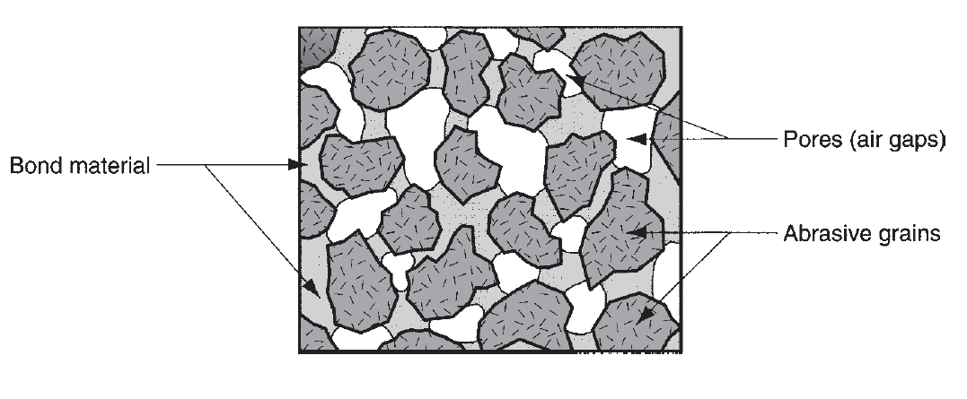
Figure 18: Typical structure of a grinding wheel.
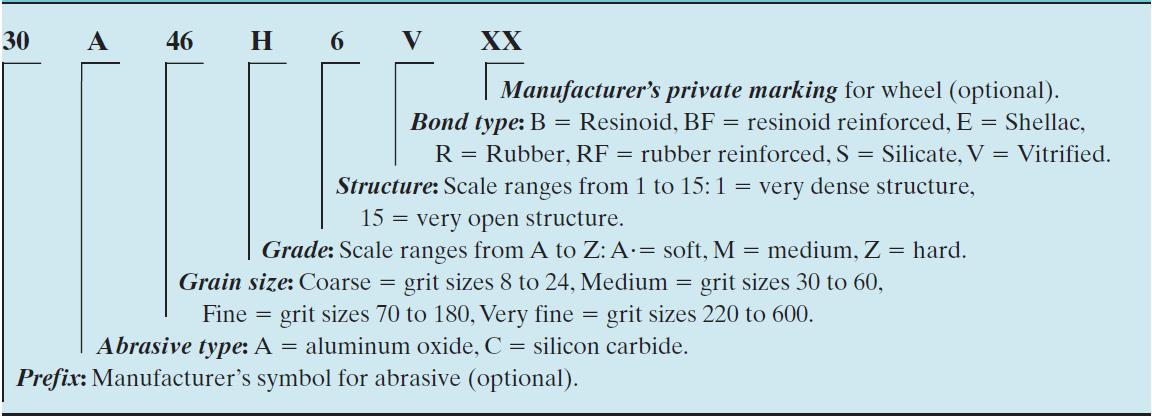
Marking system for conventional grinding wheels as defined by ANSI Standard B74.13-1977 |
|
Wheel grade indicates the grinding wheel’s bond strength in retentive the abrasive grits throughout cutting. This can be mostly captivated with the number of bonding material present in the wheel structure - . Grade is measured on a scale that ranges between soft and hard. ‘‘Soft’’ wheels lose grains pronto, whereas ‘‘hard’’ wheels retain their abrasive grains. Soft wheels are typically used for applications requiring low material removal rates and grinding of toil materials. Exhausting wheels are typically used to achieve high stock removal rates and for grinding of relative soft work materials.
5.4.2 Grinding Wheel Specification:
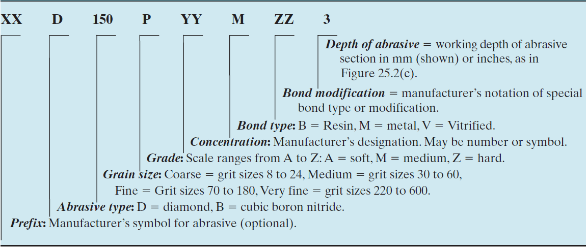
The preceding parameters will be in short designated in a standard emery wheel marking system outlined by the yank National Standards Institute (ANSI). This marking system uses numbers and letters to specify abrasive type, grit size, grade, structure, and bond material. Table presents an abbreviated version of the ANSI normal, indicating however the numbers and letters are interpreted. The standard additionally provides for extra identifications which may be used by the grinding wheel makers. The ANSI normal for diamond and isometric boron nitride grinding wheels is slightly totally different than for standard wheels. The marking system for these newer grinding wheels is given in table.
Marking system for diamond and cubic boron nitride grinding wheels as defined by ANSI Standard B74.13-1977 |
|
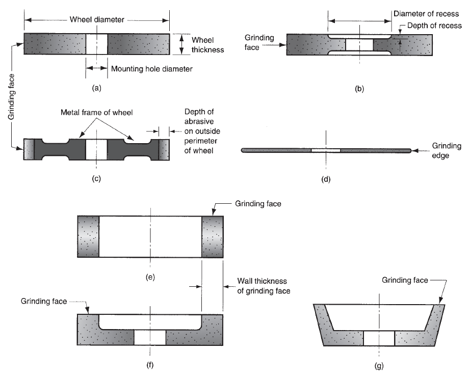
Figure 19: Some of the standard grinding wheel shapes: (a) straight, (b) recessed two sides, (c) metal wheel frame with abrasive bonded to outside circumference, (d) abrasive cutoff wheel, (e) cylinder wheel, (f) straight cup wheel, and (g) flaring cup wheel.
Grinding wheels are available a spread of shapes and sizes, as shown in figure. Configurations (a), (b), and (c) are peripheral grinding wheels, in which material removal is accomplished by the surface circumference of the wheel. A typical abrasive cutoff wheel is shown in (d) that additionally involves peripheral cutting. Wheels (e), (f), and (g) are face grinding wheels, in which the flat face of the wheel removes material from the surface.
5.4.3 Analysis of the Grinding Process:
The cutting conditions in grinding are characterised by very high speeds and extremely small cut size, compared to milling and different traditional machining operations. The peripheral speed of the wheel is decided by the rotational speed of the wheel:

where v = surface speed of wheel, m/min (ft/min); N = spindle speed, rev/min; and D = wheel diameter, m (ft).
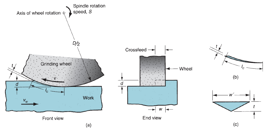
Figure 20: (a) The geometry of surface grinding, showing the cutting conditions; (b) assumed longitudinal shape and (c) cross section of a single chip.
Depth of cut d, referred to as the infeed, is the penetration of the wheel below the original work surface. Because the operation payoff, the wheel is fed laterally across the surface on each pass the work. This can be referred to as the crossfeed, and it determines the width of the grinding path w. This width, multiplied by depth d determines the cross-sectional area of the cut. In most grinding operations, the work moves past the wheel at a certain speed vw, in order that the material removal rate is

Each grain in the wheel cuts an individual chip, and whose assumed cross-sectional form is triangular. At the exit point of the grit from the work, where the chip cross section is largest, and this triangle has height t and breadth w’. In a grinding operation, we tend to have an interest in however the cutting conditions combine with the grinding wheel parameters to have an effect on (1) surface end, (2) forces and energy, (3) temperature of the surface, and (4) wheel wear.
Surface Finish: Most business grinding is performed to realize a surface end that is superior to that which is accomplished with conventional machining. The surface finish of the workpart is stricken by the dimensions of the individual chips shaped throughout grinding. One obvious factor in determinant chip size is grit size - smaller grit sizes yield higher finishes. Let us examine the scale of an individual chip. It is shown that the common length of a chip is given by

where lc is the length of the chip, mm(in); D = wheel diameter, mm (in); and d = depth of cut, or infeed, mm (in).
This assumes the chip is created by a grit that acts throughout the complete sweep arc shown within the diagram. The cross-sectional shape is triangular with breadth w’ being larger than the thickness t by a factor called the grain ratio rg, outlined by

Typical values of grain ratio are between ten and twenty.
The variety of active grits (cutting teeth) per area unit on the surface periphery of the grinding wheel is denoted by C. In general, smaller grain sizes provide larger C values. C is additionally related to the wheel structure. A denser structure means that a lot of grits per space. Based on the value of C, the quantity of chips shaped per time nc is given by

where v = wheel speed, mm/min (in/min); w = crossfeed, mm (in); and C = grits per area on the grinding wheel surface, grits/mm2 (grits/in2).
It stands to reason that surface end is improved by increasing the quantity of chips shaped per unit time on the surface for a given breadth w. Therefore, according to above equation, increasing v and/or C can improve end.
Wheel Wear: Grinding wheels wear, even as standard cutting tools wear. Three mechanisms are recognized because the principal causes of damage in grinding wheels: (1) grain fracture, (2) attritious wear, and (3) bond fracture. Grain fracture occurs once a portion of the grain breaks off, however the remainder of the grain remains warranted within the wheel. The sides of the fractured space become new cutting edges on the wheel. The tendency of the grain to fracture is named friability. High friability means that the grains fracture more readily because of the cutting forces on the grains Fc’.
Attritious wear involves dulling of the individual grains, resulting in flat spots and rounded edges. Attritious wear is analogous to tool wear in a very standard cutting tool. It is caused by similar physical mechanisms together with friction and diffusion, moreover as chemical reactions between the abrasive and therefore the work material within the presence of terribly high temperatures.
Bond fracture occurs once the individual grains are force out of the bonding material. The tendency toward this mechanism depends on wheel grade, among different factors. Bond fracture usually happens as a result of the grain has become uninteresting thanks to attritious wear, and the resulting cutting force is excessive. Sharp grains cut more efficiently with lower cutting forces; hence, they remain connected within the bond structure. Three wear regions are known. Within the initial region, the grains are initially sharp, and wear is accelerated thanks to grain fracture. This corresponds to the ‘‘break-in’’ period in conventional tool wear. Within the second region, the wear and tear rate is fairly constant, resulting in a linear relationship between wheel wear and volume of metal removed. This region is characterized by attritious wear, with some grain and bond fracture. In the third region of the wheel wear curve, the grains become uninteresting, and therefore the quantity of plowing and rubbing increases relative to cutting. Additionally, a number of the chips become clogged in the pores of the wheel. This can be referred to as wheel loading, and it impairs the cutting action and leads to higher heat and work surface temperatures. As a consequence, grinding potency decreases, and the volume of wheel removed will increase relative to the degree of metal removed. The grinding magnitude relation is a term won’t to indicate the slope of the wheel wear curve. Specifically

where GR = the grinding ratio, Vw = the volume of work material removed, and Vg = the corresponding volume of the wheel that's worn within the method.
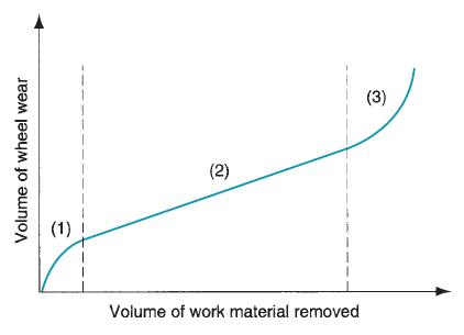
Figure 21: Typical wear curve of a grinding wheel. Wear is conveniently plotted as a function of volume of material removed, rather than as a function of time.
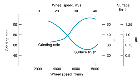
Figure 22: Grinding ratio and surface finish as a function of wheel speed.
Typical values of GR vary between ninety five and one hundred twenty five that is concerning 5 orders of magnitude less than the analogous ratio in standard machining. Grinding magnitude relation is generally increased by increasing wheel speed v. the rationale for this can be that the dimensions of the chip shaped by every grit is smaller with higher speeds, that the quantity of grain fracture is reduced. Because higher wheel speeds conjointly improve surface end, there's a general advantage in operating at high grinding speeds. However, once speeds become too high, attritious wear and surface temperatures increase. As a result, the grinding ratio is reduced and the surface end is impaired. This impact was originally reportable by Krabacher.
When the wheel is within the third region of the wear and tear curve, it should be re-sharpened by a procedure called dressing, that consists of (1) abruption the dulled grits on the outside periphery of the wheel so as to show contemporary sharp grains and (2) removing chips that have become clogged within the wheel. it's accomplished by a rotating disk, an abrasive stick, or another wheel operational at high speed, command against the wheel being dressed because it rotates. though dressing sharpens the wheel, it doesn't guarantee the shape of the wheel. Truing is an alternate procedure that not solely sharpens the wheel, but conjointly restores its cylindrical form and ensures that it's straight across its outside perimeter. The procedure uses a diamond-pointed tool (other styles of truing tools are also used) that is fed slowly and exactly across the wheel because it rotates. Avery light-weight depth is taken (0.025 mm or less) against the wheel.
5.4.4 Grinding Operations and Grinding Machines:
Grinding is historically used to end components whose geometries have already been created by different operations. Consequently, grinding machines are developed to grind plain flat surfaces, external and internal cylinders, and contour shapes admire threads. The contour shapes are usually created by special shaped wheels that have the other of the desired contour to be imparted to the work. Grinding is additionally utilized in tool rooms to form the geometries on cutting tools. additionally to those traditional uses, applications of grinding are expanding to incorporate a lot of high speed, high material removal operations. Our discussion of operations and machines during this section includes the subsequent types:
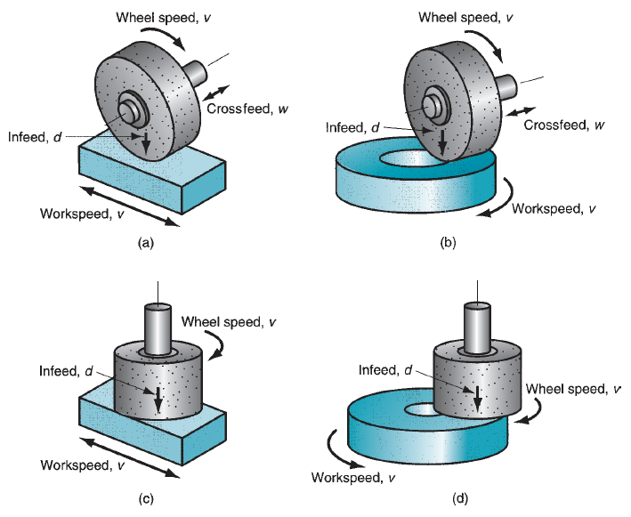
Figure 23: Four types of surface grinding: (a) horizontal spindle with reciprocating worktable, (b) horizontal spindle with rotating worktable, (c) vertical spindle with reciprocating worktable, and (d) vertical spindle with rotating worktable.
(1) Surface grinding,
(2) Cylindrical grinding,
(3) Centerless grinding,
(4) Creep feed grinding, and
(5) Different grinding operations.
Surface Grinding: Surface grinding is often wont to grind plain flat surfaces. It is performed using either the edge of the wheel or the flat face of the wheel. Because the work is often command in a very horizontal orientation, peripheral grinding is performed by rotating the wheel a couple of horizontal axis, and face grinding is performed by rotating the wheel a couple of vertical axis. In either case, the relative motion of the workpart is achieved by reciprocating the work past the wheel or by rotating it. These possible combinations of wheel orientations and workpart motions give the four styles of surface grinding machines. Of the four types, the horizontal spindle machine with reciprocatory work table is the most common. Grinding is accomplished by reciprocatory the work longitudinally under the wheel at an awfully little depth (infeed) and by feeding the wheel transversely into the work a precise distance between strokes. In these operations, the width of the wheel is usually under that of the work. In addition to its standard application, a grinding machine with horizontal spindle and reciprocating table is wont to type special contoured surfaces by employing a shaped grinding wheel. Rather than feeding the wheel transversally across the work as it reciprocates, the wheel is plunge-fed vertically into the work. The form of the formed wheel is therefore imparted to the surface.
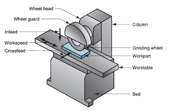
Figure 24: Surface grinder with horizontal spindle and reciprocating worktable.
Grinding machines with vertical spindles and reciprocatory tables are come upon therefore that the wheel diameter is larger than the work breadth. Consequently, these operations will be performed without employing a cross feed motion. Instead, grinding is accomplished by reciprocating the work past the wheel, and feeding the wheel vertically into the work to the desired dimension. This configuration is capable of achieving a very flat surface on the work. The vertical spindle machines are a lot of common. Because of the comparatively giant surface contact area between wheel and workpart, vertical spindle-rotary table grinding machines are capable of high metal removal rates once equipped with acceptable grinding wheels.
Cylindrical Grinding: As its name suggests, cylindrical grinding is employed for rotational parts. These grinding operations divide into 2 basic varieties: (a) external cylindrical grinding and (b) internal cylindrical grinding. External cylindrical grinding (also referred to as center-type grinding to differentiate it from centerless grinding) is performed very similar to a turning operation. The grinding machines used for these operations closely jibe a shaping machine during which the tool post has been replaced by a high-speed motor to rotate the wheel. The cylindrical work is rotated between centers to produce a surface speed of eighteen to thirty m/min (60 to a hundred ft/min), and the grinding wheel, rotating at 1200 to 2000 m/min (4000 to 6500 ft/min), is engaged to perform the cut. There are 2 styles of feed motion doable, traverse feed and plunge-cut. In traverse feed, the wheel is fed in a very direction parallel to the axis of rotation of the workpart. The infeed is about inside a variety generally from0.0075 to 0.075mm (0.0003 to 0.003 in). A longitudinal reciprocatory motion is usually given to either the work or the wheel to boost surface end. In plunge-cut, the grinding wheel is fed radially into the work. Shaped grinding wheels use this kind of feed motion.
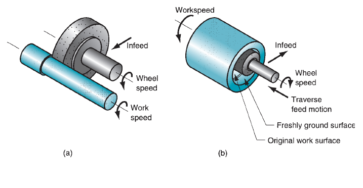
Figure 25: Two types of cylindrical grinding: (a) external, and (b) internal.
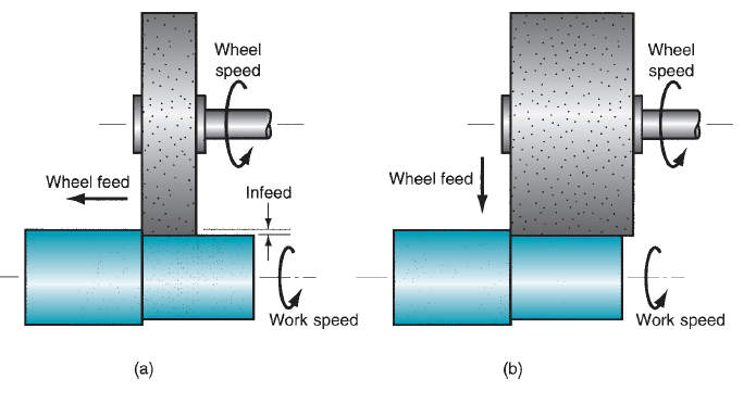
Figure 26: Two types of feed motion in external cylindrical grinding: (a) traverse feed, and (b) plunge-cut.
External cylindrical grinding is employed to complete components that are machined to approximate size and warmth treated to desired hardness. The components embrace axles, crankshafts, spindles, bearings and bushings, and rolls for rolling mills. The grinding operation produces the final size and needed surface end on these hardened components.
Internal cylindrical grinding operates somewhat sort of a boring operation. The workpiece is typically held in a very chuck and turned to produce surface speeds of twenty to 60m/min (75 to 200 ft/min).Wheel surface speeds just like external cylindrical grinding are used. The wheel is fed in either of 2 ways: traverse feed, or plunge feed. Obviously, the wheel diameter in internal cylindrical grinding should be smaller than the initial bore hole. This usually means that the wheel diameter is sort of little, necessitating terribly high rotational speeds in order to realize the specified surface speed. Internal cylindrical grinding is used to finish the hardened within surfaces of bearing races and bushing surfaces.
Centerless Grinding: Centerless grinding is an alternate method for grinding external and internal cylindrical surfaces. As its name suggests, the work isn't command between centers. This results in a discount in work handling time; thus, centerless grinding is often used for high-production work. The setup for external centerless grinding consists of two wheels: the wheel and a regulation wheel. The workparts, which may be many individual short items or long rods, are supported by a rest blade and fed through between the 2 wheels.
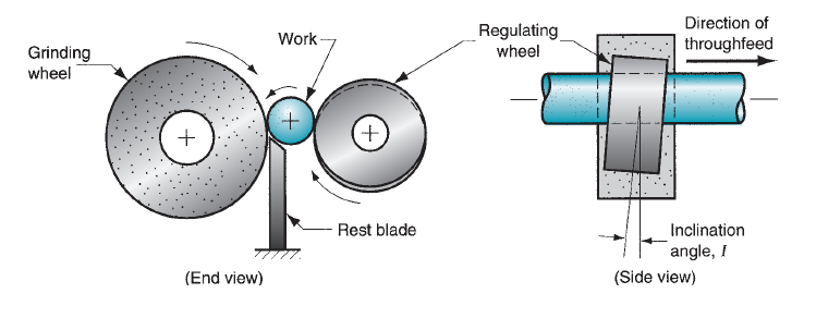
Figure 27: External centerless grinding.
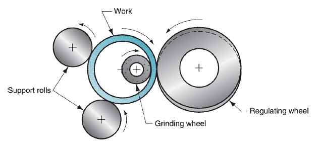
Figure 28: Internal centerless grinding.
The wheel will the cutting, rotating at surface speeds of 1200 to 1800 m/min (4000 to 6000 ft/min).The regulation wheel rotates at much lower speeds and is inclined at a small angle I to manage through feed of the work. The following equation is wont to predict through feed rate, based on inclination angle and other parameters of the method:

where fr = through feed rate, mm/min (in/min); Dr = diameter of the regulation wheel, mm (in); Nr = rotational speed of the regulation wheel, rev/min; and I = inclination angle of the regulating wheel.
In place of the rest blade, 2 support rolls are wont to maintain the position of the work. The regulating wheel is inclined at a little inclination angle to manage the feed of the work past the grinding wheel. Because of the requirement to support the wheel, through feed of the work as in external centerless grinding isn't doable. So this grinding operation cannot achieve similar high-production rates as within the external centerless method. Its advantage is that it's capable of providing terribly close concentricity between internal and external diameters on a hollow part admire a roller bearing race.
Creep Feed Grinding: A comparatively new variety of grinding is feed grinding, developed around 1958. Feed grinding is performed at terribly high depths of cut and very low feed rates; thence, the name feed. Depths of cut in feed grinding are a thousand to 10000 times larger than in conventional surface grinding, and also the feed rates are reduced by concerning identical proportion.
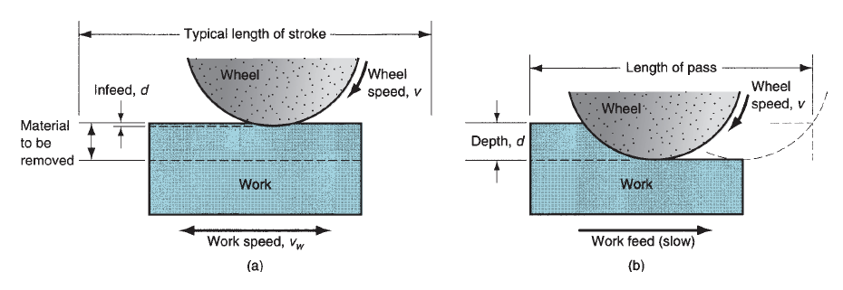
Figure 29: Comparison of (a) conventional surface grinding and (b) creep feed grinding.
However, material removal rate and productivity are augmented in creep feed grinding as a result of the wheel is endlessly cutting. This contrasts with typical surface grinding in which the reciprocating motion of the work ends up in important lost time during each stroke. Creep feed grinding will be applied in each surface grinding and external cylindrical grinding. Surface grinding applications embody grinding of slots and profiles. The process seems particularly suited to those cases within which depth-to-width ratios are comparatively giant. The cylindrical applications embody threads, shaped gear shapes, and alternative cylindrical components. The term deep grinding is employed in Europe to explain these external cylindrical feed grinding applications. The introduction of grinding machines designed with special options for creep feed grinding has spurred interest within the method. The options embody high static and dynamic stability, extremely correct slides, 2 to a few times the spindle power of typical grinding machines, consistent table speeds for low feeds, hard-hitting grinding fluid delivery systems, and dressing systems capable of dressing the grinding wheels throughout the method. Typical advantages of feed grinding include: (1) high material removal rates, (2) improved accuracy for shaped surfaces, and (3) reduced temperatures at the surface.
5.4.5 Connected Abrasive Processes:
Other abrasive processes embody honing, lapping, superfinishing, polishing, and buffing. They are used completely as finishing operations. The initial half form is made by some other process; then the part is ended by one among these operations to realize superior surface finish. For comparison, we tend to additionally gift corresponding information for grinding. Another category of finishing operations, referred to as mass finishing, is used to end elements in bulk instead of singly. These mass finishing ways also are used for improvement and deburring.
Honing:
Honing is abrasive method performed by a collection of secured abrasive sticks. A common application is to end the bores of combustion engines. Alternative applications include bearings, hydraulic cylinders, and gun barrels. Surface finishes of around 0.12 µm (5 µ-in) or slightly higher is usually achieved in these applications. Additionally, honing produces a characteristic cross-hatched surface that tends to retain lubrication during operation of the element, therefore contributive to its operated and repair life.
Usual part geometries for honing, lapping, superfinishing, polishing, and buffing. |
|
The honing tool consists of a group of secured abrasive sticks. Four sticks are used on the tool shown within the figure, however the amount depends on hole size. 2 to four sticks would be used for little holes (e.g., gun barrels), and a dozen or additional would be used for larger diameter holes. The motion of the honing tool could be a combination of rotation and linear reciprocation, regulated in such the way that a given purpose on the abrasive stick will not trace a similar path repeatedly. This rather complicated motion accounts for the crosshatched pattern on the bore surface. Honing speeds are fifteen to one hundred fifty m/min (50 to five hundred ft/min). Throughout the method, the sticks are ironed outward against the outlet surface to produce the desired abrasive cutting action. Hone pressures of one to three MPa (150 to 450 lb/in2) are typical.
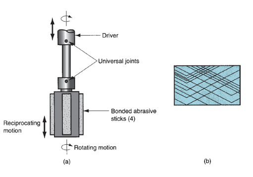
Figure 30: The honing process: (a) the honing tool used for internal bore surface, and (b) cross-hatched surface pattern created by the action of the honing tool.
The honing tool is supported within the hole by 2 universal joints, therefore inflicting the tool to follow the antecedently outlined hole axis. Honing enlarges and finishes the outlet but cannot modification its location. Grit sizes in honing vary between thirty and 600. A similar trade-off between better finish and quicker material removal rates exists in honing as in grinding. The number of material far from the surface throughout a honing operation could also be the maximum amount as 0.5mm (0.020 in), however is typically abundant below this. A cutting fluid should be utilized in honing to cool and lubricate the tool and to assist take away the chips.
Lapping:
Lapping is an abrasive method wont to turn out surface finishes of maximum accuracy and smoothness. It’s utilized in the assembly of optical lenses, bimetal bearing surfaces, gages, and alternative elements requiring superb finishes. Metal elements that are subject to fatigue loading or surfaces that has to be wont to establish a seal with a union half are usually lapped. Instead of a guaranteed abrasive tool, covering uses a fluid suspension of terribly small abrasive particles between the piece of work and also the lapping tool. The fluid with abrasives is observed as the lapping compound and has the final look of a chalky paste. The fluids used to make the compound embody oils and coal oil. Common abrasives are metal oxide and carbide with typical grit sizes between three hundred and 600. The covering tool is termed a lap, and it's the reverse of the required form of the workpart. To accomplish the process, the lap is ironed against the work and captive back and forth over the surface in a figure-eight or alternative motion pattern, subjecting all parts of the surface to the same action. Covering is usually performed by hand; however covering machines accomplish the process with larger consistency and potency.

Figure 31: The lapping process in lens-making.
Materials wont to create the lap vary from steel and forged iron to copper and lead. Wood laps have additionally been created. As a result of a covering compound is employed instead of a bonded abrasive tool, the mechanism by that this method works is somewhat completely different than grinding and honing. It’s hypothesized that 2 different cutting mechanisms are at work in covering. The primary mechanism is that the abrasive particles roll and slide between the lap and also the work, with terribly tiny cuts occurring in each surface. The second mechanism is that the abrasives become embedded within the lap surface and also the cutting action is incredibly similar to grinding. It’s probably that covering could be a combination of those two mechanisms, relying on the relative hardness of the work and also the lap. For laps manufactured from soft materials, the embedded grit mechanism is emphasized; and for exhausting laps, the rolling and sliding mechanism dominates.
Superfinishing:
Superfinishing is an abrasive process similar to honing. Both processes use a bonded abrasive stick moved with a reciprocating motion and pressed against the surface to be finished. Superfinishing differs from honing in the following respects: (1) the strokes are shorter, 5 mm (3/16 in); (2) higher frequencies are used, up to 1500 strokes per minute; (3) lower pressures are applied between the tool and the surface, below 0.28 MPa (40 lb/in2); (4) workpiece speeds are lower, 15 m/min (50 ft/min) or less; and (5) grit sizes are generally smaller.
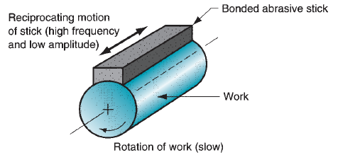
Figure 32: Superfinishing on an external cylindrical surface.
The relative motion between the abrasive stick and the work surface is varied so that individual grains do not retrace the same path. A cutting fluid is used to cool the work surface and wash away chips. In addition, the fluid tends to separate the abrasive stick from the work surface after a certain level of smoothness is achieved, thus preventing further cutting action. The result of these operating conditions is mirror-like finishes with surface roughness values around 0.025 µm (1 µ-in). Superfinishing can be used to finish flat and external cylindrical surfaces.
Polishing and Buffing:
Polishing is used to remove scratches and burrs and to smooth rough surfaces by means of abrasive grains attached to a polishing wheel rotating at high speed - around 2300 m/min (7500 ft/min).The wheels are made of canvas, leather, felt, and even paper; thus, the wheels are somewhat flexible. The abrasive grains are glued to the outside periphery of the wheel. After the abrasives have been worn down and used up, the wheel is replenished with new grits. Grit sizes of 20 to 80 are used for rough polishing, 90 to 120 for finish polishing, and above 120 for fine finishing. Polishing operations are often accomplished manually. Buffing is similar to polishing in appearance, but its function is different. Buffing is used to provide attractive surfaces with high luster. Buffing wheels are made of materials similar to those used for polishing wheels - leather, felt, cotton, etc. - but buffing wheels are generally softer. The abrasives are very fine and are contained in a buffing compound that is pressed into the outside surface of the wheel while it rotates. This contrasts with polishing in which the abrasive grits are glued to the wheel surface. As in polishing, the abrasive particles must be periodically replenished. Buffing is usually done manually, although machines have been designed to perform the process automatically. Speeds are generally 2400 to 5200 m/min (8000 to 17,000 ft/min).
