Unit-3
Riveted Joints
A Rivet is a short cylindrical rod having a head and a tapered tail. The main body of the rivet is called shank.
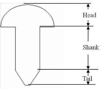
Figure 1: Rivets and its parts
3.1.1 Important terms used in rivet joints
Few parameters, which are required to specify arrangement of rivets in riveted joints are as follows:
a) Pitch: This is the distance between two centres of the consecutive rivets in a Single row. (usual symbol p)
b) Back Pitch: This is the shortest distance between two successive rows in a multiple riveted joint. (usual symbol bp)
c) Diagonal pitch: This is the distance between the centres of rivets in adjacent rows of zigzag riveted joint. (usual symbol pd)
d) Margin or marginal pitch: This is the distance between the centre of the rivet
hole to the nearest edge of the plate. (usual symbol m)
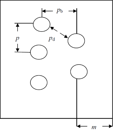
Figure 2: Important design parameters of riveted joints
Key takeaways
A Rivet is a short cylindrical rod having a head and a tapered tail. The main body of the rivet is called shank.
The rivet joints are analyzed on the basis of following assumptions:
1 Rivets are loaded in shear the load is distributed in proportion to the shear area of the rivets.
2 There are no bending or direct stresses in rivets.
3 Rivet holes in plate do not weaken the plate in compression.
Design of boiler joints
In general, for longitudinal joint, butt joint is adopted, while for circumferential joint, lap joint is preferred.
Design of longitudinal butt joint


8. Diameter of rivets: The diameter of the rivets may be determined from the empirical relation, d = 6 t for t ≥ 8mm
KEYWAY POINT:
1) The diameter of rivet should not be less than the plate thickness.
2) If the plate thickness is less than 8 mm, the diameter of the rivet is determined by equating the shearing resistance of the rivet to its crushing resistance.
9. Pitch of the rivets: The pitch of the rivets may be obtained by equating the tearing resistance of the plate to the shearing resistance of the rivets. However, it should be noted that,
(i) The pitch of the rivets should not be less than 2d.
(ii) The maximum value of the pitch, for a longitudinal joint is given by,
 = ct + 41.28mm where ‘c’ is a constant.
Note: If the pitch of the rivets obtained by equating the tearing resistance to the shearing resistance is more than Pmax, then the value of Pmax can be adopted.
10. Row (transverse) pitch:
(i). For equal number of rivets in more than one row for lap joint or butt joint, the row pitch should not be less than, 0.33 p + 0.67d for zig-zag riveting and 2d, for chain riveting.
(ii). For joints in which the number of rivets in the rows is half the number of rivets in the inner rows, and if the inner rows are chain riveted, the distance between the outer row and the next row, should not be less than, 0.33 p + 0.67d or 2d, whichever is greater. The distance between the rows in which there are full number of rivets, should not be less than 2d.
(iii). For joints in which the number of rivets in outer row is half the number of rivets in inner rows, and if the inner rows are zig-zag riveted, the distance between the outer row and the next row, should not be less than, 0.2 p +1.15d. The distance between the rows in which there are full number of rivets (zig-zag), should not be less than, 0.165 p + 0.67d.
Note: p is the pitch of the rivets in the outer row.
11. Thickness of butt straps: The thickness of butt strap(s) is given by, (in no case it should not be less than 10 mm).
 = 1.125t , for ordinary single butt strap (chain riveting)
When two unequal widths of butt straps are employed, the thickness of butt straps are given by,  = 0.75t , for wide strap on the inside and
  = 0.625t , for narrow strap on the outside.
Note: The thickness of butt strap, in no case, shall be less than 10 mm.
6. Margin: The margin ‘m’ is generally followed as 1.5d.
Key takeaways
The most important formula for determining the thickness of the plate of boiler along with the pitch and other parameters.

The movements in hardened material that can cause cracking can originate from:
Joints will be designated by terminology based on the following characteristics: resistance, configuration, formation, location, type of structure and function.
Key takeaways
Resistance, configuration and other parameters are to be considered while joining of a structure.
Initial tightening load
When a nut is tightened over a screw following stresses are induced:
a) Tensile stresses due to stretching of the bolt
b) Torsional shear stress due to frictional resistance at the threads.
c) Shear stress across threads
d) Compressive or crushing stress on the threads
e) Bending stress if the surfaces under the bolt head or nut are not perfectly normal to the bolt axis.
The initial tension in the bolt may be estimated by an empirical relation P1=284 d kN, where the nominal bolt diameter d is given in mm. The relation is used for making the joint leak proof.
If leak proofing is not required half of the above estimated load may be used. However, since initial stress is inversely proportional to square of the diameter-

Bolts of smaller diameter such as M16 or M8 may fail during initial tightening.
Key takeaways:
If leak proofing is not required half of the above estimated load may be used. However, since initial stress is inversely proportional to square of the diameter-

Bolts of smaller diameter such as M16 or M8 may fail during initial tightening.
There are many applications of the bolted joints which are subjected to eccentric loading such as a wall bracket, pillar crane, etc. The eccentric load may be
1. Parallel to the axis of the bolts,
2. Perpendicular to the axis of the bolts, and
3. In the plane containing the bolts.
Eccentric Load Acting Parallel to the Axis of Bolts:
Consider a bracket having a rectangular base bolted to a wall by means of four bolts as shown in Fig. 3A little consideration will show that each bolt is subjected to a direct tensile load of  =
= 
Where n is the number of bolts.
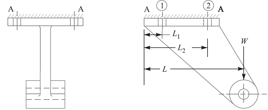
Figure 3: Eccentric load acting parallel to the axis of bolts.
Let w be the load in a bolt per unit distance due to the turning effect of the bracket and let  and
and be the loads on each of the bolts at distances
  and
and  from the tilting edge.
Load on each bolt at distance ,
,
 = w.
= w.
and moment of this load about the tilting edge

Similarly, load on each bolt at distance  ,
,
 = w.
= w.
And moment of this load about the tilting edge

Total moment of the load on the bolts about the tilting edge
 …..(i)
Also, the moment due to load W about the tilting edge
= W.L …..(ii)
From equations (i) and (ii), we have
 …..(iii)
The most heavily loaded bolts are those which are situated at the greatest
distance from the tilting edge. Tensile load on each bolt at distance L2,

and the total tensile load on the most heavily loaded bolt,
 ……(iv)
If dc is the core diameter of the bolt and σt is the tensile stress for the bolt material, then total tensile load,
 …….(v)
From equations (iv) and (v), the value of dc may be obtained.
Eccentric Load Acting Perpendicular to the Axis of Bolts
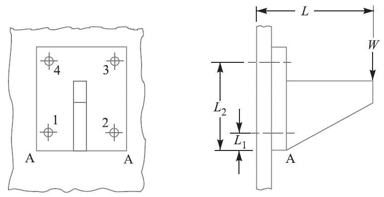
Figure 4: Eccentric load perpendicular to the axis
The bolts are subjected to direct shearing load which is equally shared by all the bolts. Therefore, direct shear load on each bolts,
 = W/n, where n is number of bolts.
In this case, bolts 3 and 4 are heavily loaded.
∴ Maximum tensile load on bolt 3 or 4,

When the bolts are subjected to shear as well as tensile loads, then the equivalent loads may be determined by the following relations :
Equivalent tensile load,

And equivalent shear load,

Knowing the value of equivalent loads, the size of the bolt may be determined for the given allowable stresses.
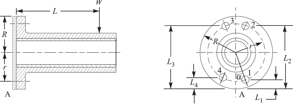
3.6.1 Eccentric Load on a Bracket with Circular Base
Consider a round flange bearing of a machine tool having four bolts
as shown in Fig.
(a) (b)
Figure 5: Eccentric load on a bracket with circular base.
Let R = Radius of the column flange,
r = Radius of the bolt pitch circle,
w = Load per bolt per unit distance from the tilting edge,
L = Distance of the load from the tilting edge, and
 = Distance of bolt centres from the tilting edge A.
On equating the external moment W × L to the sum of the
resisting moments of all the bolts,
 ………….(i)
From the geometry of the Fig.(b),

Substituting these values in equation (i),

∴ Load in the bolt situated at 1 is

This load will be maximum when cos α is minimum i.e. when cos α = – 1 or α = 180°.
∴ Maximum load in a bolt is

In general, if there are n number of bolts, then load in a bolt

and maximum load in a bolt,

If the direction of load is fixed, then the maximum load on the bolts may be reduced by locating the bolts in such a way that two of them are equally stressed. In such a case, maximum load is given by

Key takeaways:
Total moment of the load on the bolts about the tilting edge
 …..(i)
is the important formula.
A welded joint is a permanent joint which is obtained by the fusion of the edges of the two parts to be joined together, with or without the application of pressure and a filler material. Welding is a very commonly used permanent joining process.
Types of welded joints
Welded joints are primarily of two kinds: -
a) Lap or fillet joint: obtained by overlapping the plates and welding their edges. The fillet joints may be single transverse fillet, double transverse fillet or parallel fillet joints.
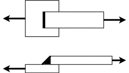
Figure 6: Single transverse lap joint
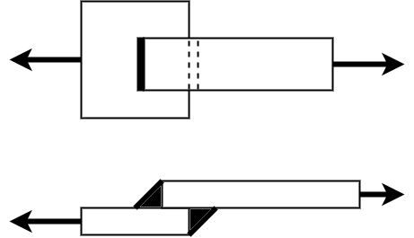
Figure 7: Double transverse lap joint

Figure 8: Parallel lap joint
b) Butt joints: formed by placing the plates edge to edge and welding them. Grooves are sometimes cut (for thick plates) on the edges before welding. According to the shape of the grooves, the butt joints may be of different types, e.g.,
a) Square butt joint

b) Single V-butt joint, double V-butt joint

c) Single U-butt joint, double U-butt joint
d) Single J-butt joint, double J-butt joint
e) Single bevel-butt joint, double bevel butt joint

Key takeaways
Single transverse, double transverse and parallel lap joints are the important classification of the joints along with the Square butt joint, single V-butt joint.
The stresses are obtained, on the following assumptions:

Figure 9: Stresses for welded joints.
3.9.1 Axially Loaded Unsymmetrical Welded Sections
Consider an angle section as shown in Figure 10.

Figure 10: Axially loaded unsymmetrical welded section
Let  = Length of weld at the top,
 = Length of weld at the bottom,
l = Total length of weld =  +
+ 
P = Axial load,
a = Distance of top weld from gravity axis,
b = Distance of bottom weld from gravity axis, and
f = Resistance offered by the weld per unit length.
Moment of the top weld about gravity axis= la × f × a
and moment of the bottom weld about gravity axis= lb× f × b
Since the sum of the moments of the weld about the gravity axis must be zero, therefore,
la × f × a – lb× f × b = 0
or la × a = lb× b ...(i)
We know that l = la + lb...(ii)
∴ from equations (i) and (ii), we have

3.9.2 Long fillet weld subjected to torsion:
Consider a vertical plate attached to a horizontal plate by two identical fillet welds as shown in Figure 11.
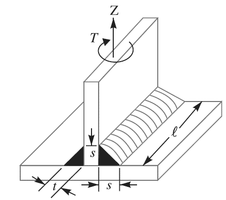
Figure 11: Long fillet weld subjected to torsion.
Let T = Torque acting on the vertical plate,
l = Length of weld,
s = Size (or leg) of weld,
t = Throat thickness, and
J = Polar moment of inertia of the weld section

The effect of the applied torque is to rotate the vertical plate about the Z-axis through its mid point. This rotation is resisted by shearing stresses developed between two fillet welds and the horizontal plate. It is assumed that these horizontal shearing stresses vary from zero at the Z-axis and maximum at the ends of the plate. This variation of shearing stress is analogous to the variation of normal stress over the depth (l) of a beam subjected to pure bending.

The maximum shear stress occurs at the throat and is given by-

3.9.3 Circular fillet weld subjected to bending moment
Consider a circular rod connected to a rigid plate by a fillet weld as shown in Figure 12.
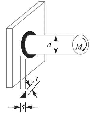
Figure 12: Circular fillet weldsubjected to bending moment
Let d = Diameter of rod,
M = Bending moment acting on the rod,
s = Size (or leg) of weld,
t = Throat thickness,
Z = Section modulus of the weld section
=
We know that the bending stress,

The maximum bending stress occurs on the throat of theweld which is inclined at 45° to the horizontal plane.
∴ Length of throat, t = s*sin 45° = 0.707*s
and maximum bending stress,

Because of many intricacies involved in design of a welded joint, codes are extensively used to design such joint when it experiences variable loading. The value of the maximum fluctuating load is not allowed to exceed a limit specified in the code. This value depends on
a. Type of the joint
b. type of stress experienced by the joint
c. A load factor K defined as the ratio of the minimum stress to the maximum stress. When the load is a steady one the factor takes unit value. For a complete reversal of stress the value of K = -1.
The design stress for completely reversing load is calculated using the formula.

Where  = design stress for complete reversal of stress
 = allowable fatigue stress
 = fatigue stress concentration factor tabulated below
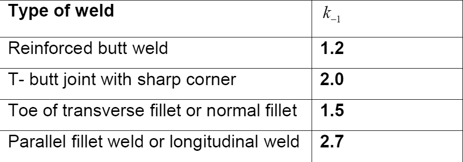
The values of the allowable fatigue stress ( ) are also tabulated in the design code for various weld geometries. For example, the allowable fatigue stress for fillet weld is given (assuming the weld to be a line) as

Where, w denotes the leg size of the fillet weld measured in centimetre. The design is found to be safe if the maximum value of the fluctuating stress is found to be lesser than the design stress.
Key takeaways:
 is the most important formula used for determining weld at the fluctuation load.
References: