Unit-5
Design of transmission elements
5.1.1 Spur gear:
The gears connecting two parallel and coplanar shafts are known as spur gear.
5.1.1.1 System of gear teeth:
b. The 14.50 composite systems are used for general purpose gears. It is stronger but has no interchange ability. The tooth profile of this system has cycloidal curves at the top and bottom and involute curve at the middle portion.
c. The tooth profile of the 14.50 full depth involute systems was developed for use with gear hobs for spur and helical gears.
d. The tooth profile of the 200 full depth involute systems may be cut by the hobs. The increase of the pressure angle from14.50 to 200 results in a stronger tooth, because the tooth acting as a beam is wider at the base.
e. The 200 stub involute systems have a strong tooth to take heavy loads.
5.1.1.2 Contact ratio:
It is defined as the ratio of the length of the arc of contact to the circular pitch.
Contact ratio=Length of arc of contact/p
Where, p=circular pitch=πm
5.1.1.3 Standard proportions of gear systems:
S.No. | Particulars | 14(1/2)0 composite or full depth involute system(m) | 200full depth involute system(m) | 200 stub involute system(m) |
1. | Addendum | 1 | 1 | 0.8 |
2. | Dedendum | 1.25 | 1.25 | 1 |
3. | Working Depth | 2 | 2 | 1.60 |
4. | Minimum tooth depth | 2.25 | 2.25 | 1.80 |
5. | Tooth Thickness | 1.5708 | 1.5708 | 1.5708 |
6. | Minimum Clearance | 0.25 | 0.25 | 0.2 |
7. | Fillet radius at root | 0.4 | 0.4 | 0.4 |
5.1.1.4 Design considerations:
Following are the considerations met in the design of gear drive:
5.1.1.5 Beam strength of gear tooth:
It is determined from an equation known as Lewis and the load carrying ability of the toothed gear as determined by this equation gives satisfactory results.
Consider each tooth as cantilever beam loaded by a normal load (WN)
It is resolved into two components that is tangential (WT) component and radial component (WR) acting perpendicular and parallel to the line of tooth respectively.
The tangential component (WT) induces a bending stress which tends to break the tooth.
The radial component (WT) induces a compressive stress of relatively small magnitude; therefore its effect on the tooth may be neglected. Hence, the bending stress is used as the basis for design calculations.
The critical or the section of maximum bending stress may be obtained by drawing a parabola through A and tangential to the tooth curves at B and C.
The tooth is larger than the parabola at every section except BC is the section of maximum stress or the critical section.
Let, h=Length of the tooth
T= thickness of the tooth
b =width of the face
The maximum value of the bending stress at the section BC is given by
σw =My/I, where, M= maximum bending moment
y=half of the thickness, I=moment of inertia about the centre.
Substituting, the values for M, y and I in above equation, we get
σw=[(WT*h)t/2]/(bt3/12)
=(WT*h)6/bt2
Let, t=xpc and h=kpc where x and k are constants
WT= σw b(x2pc2)/6kpc
The value of y in terms of the number of teeth may be expressed as follows:
y =0.124-(0.684/T), for 14.50 composite and full depth involute system.
= 0.154-(0.912/T), for 200 full depth involute system.
=0.175- (0.841/T), for 200 stub system.
Key takeaways:
Pressure angle, Breakage of tooth due to static and dynamic load and Surface Destruction are the failures of gear tooth.
5.1.2 Helical Gear:
These are the spur gears in which teeth are inclined to the axis of the shaft. These are also known as spiral gears.
5.1.2.1 Terminology
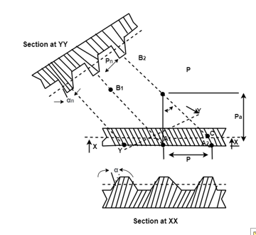
Helix angle: It is defined as the angle between the axis of the shaft and the centre line of the tooth taken on the pitch plane.
Transverse circular pitch (p)
The distance A1A2 in figure 2.2 is called the transverse circular pitch (p), which is measured in the plane of rotation.
Normal circular pitch (pn) The distance AC1 in figure is called the normal circular pitch (pn), which is measured in a plane perpendicular to the tooth elements.


From above expression, We get

where Pn and P are normal and transverse diametral pitches respectively. using P=1/m, we get
We get,
where,
mn = normal module (mm)
m = transverse module (mm)
Axial pitch (pa) In figure 2.2in triangle A1A2B2 the distance A1B2 represents the axial pitch, which is given by the following formula.

Transverse pressure angle: Pressure angle in transverse plane is known as the transverse pressure angle.
Normal pressure angle: Pressure angle in normal plane is known as the normal pressure angle.
Relation between transverse and normal pressure angle is given by following equation.

Pitch circle diameter (d) Pitch circle diameter of helical gear is calculated by the following relation,

Where, z= number of teeth on the gear.
Central distance (a) the centre to centre distance a between the two helical gears having zl and z2 as the number of teeth is given by,

5.1.2.2 Forces components on a tooth of helical gear:
The direction of tangential component for a driving gear is opposite to the direction of rotation, and that for a driven gear is same as the direction of rotation.
2. Radial Component of force (WN):
The radial component on the pinion acts toward the centre of the pinion and on the gear acts towards the centre of the gear.
3. Axial Component of force (WA): The direction of the thrust component for the driven gear will be opposite to that driving gear.
WA=WTtanα
Key Takeaways:
The major components of forces of helical gear are Tangential Component of forces (WT), Radial Component of force (WN), and Axial Component of force (WA)
5.1.3 Bevel gears:
These are used for transmitting power at constant velocity ratio between two shafts whose axes intersect at certain angle.
Terminology of bevel gear:
A bevel gear is in the form of the frustum of a cone. The following terms are important in terminology of bevel gears:
(i) Pitch Cone Pitch cone is an imaginary cone, the surface of which contains the pitch lines of all teeth in the bevel gear.
(ii) Cone Centre The apex of the pitch cone is called the cone centre. It is denoted by O.
(iii) Cone Distance Cone distance is the length of the pitch-cone element. It is also called pitch-cone radius. It is denoted by A0 and it is given by

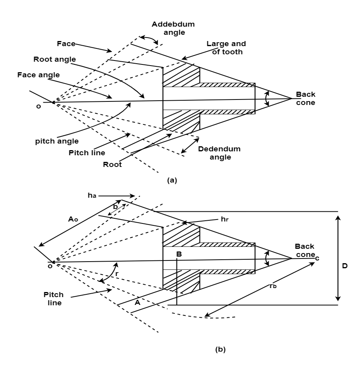
Figure: Bevel gear
(iv) Pitch Angle The angle that the pitch line makes with the axis of the gear, is called the pitch angle. It is denoted by g. The pitch angle is also called centre angle.
(v) Addendum Angle It is the angle subtended by the addendum at the cone centre. It is denoted by a.
(vi) Dedendum Angle It is the angle subtended by the dedendum at the cone centre. It is denoted by d.
(vii) Face Angle It is the angle subtended by the face of the tooth at the cone centre.
Face angle = pitch angle + addendum angle = g + a
(viii) Root Angle It is the angle subtended by the root of the tooth at the cone centre.
Root angle = pitch angle – dedendum angle = g – d
(ix) Back Cone The back cone is an imaginary cone and its elements are perpendicular to the elements of the pitch cone.
(x) Back Cone Distance It is the length of the back cone element. It is also called back cone radius. It is denoted by rb.
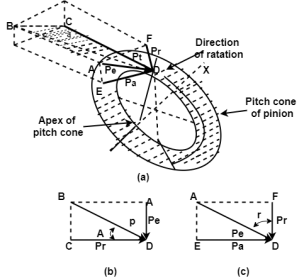
In force analysis, it is assumed that the resultant tooth force between two meshing teeth of a pair of bevel gears is concentrated at the midpoint along the face width of the tooth. The resultant force P has following three components shown in figure 2.2:
Pt = tangential or useful component (N)
Pr = radial component (N)
Pa = axial or thrust component (N)
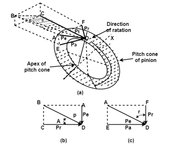
In figure: (a) from triangle BCD Figure: Component of tooth forces

Where,
Ps = separating component (N)
Tan α = pressure angle (degrees)
Force | Expression |
Tangential force (Pt) |
|
Radial force (Pr) |
|
Axial or thrust force (Pa) |
|
Where,
T = torque transmitted by gears (N-mm)
rm = radius of the pinion at midpoint along the face width (mm), and given by expression

Key takeaways:
|
|
|
These are the, tangential, radial, and axial force respectively which comes in force analysis.
Beam Strength of Bevel Gear:
In order to determine the beam strength of the tooth of a bevel gear, it is considered to be equivalent to a formative spur gear in a plane perpendicular to the tooth element. Consider an elemental section of the tooth at a distance x from the apex O and having a width dx. Applying the Lewis equation to a formative spur gear at a distance x from the apex.
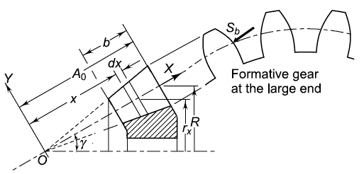

(Sb) = beam strength of the elemental section (N)
mx = module of the section (mm)
bx= face width of elemental section (mm)
Y = Lewis form factor based on virtual number of teeth
From figure 2.3

At elemental section

At the large end of the tooth

We get

And


Upon integration we get,

Assuming beam strength (Sb) as the tangential force at the large end of tooth,

Hence,

The face width of the bevel gear is limited to one-third of the cone distance. Therefore, the last term in the bracket will never be more than (1/27). Neglecting the last term,

where,
Sb = beam strength of the tooth (N)
m = module at the large end of the tooth (mm)
b = face width (mm)
σb = permissible bending stress (Sut/3) (N/mm2)
Y = Lewis form factor based on formative number of teeth
A0= cone distance (mm)
 is the bevel factor.
Wear strength of bevel gears
The contact between two meshing teeth of straight bevel gears is a line contact, which is similar to that of spur gears. In order to determine the wear strength, the bevel gear is considered to be equivalent to a formative spur gear in a plane which is perpendicular to the tooth at the large end. Applying Buckingham’s equation to these formative gears,

Where,
b = face width of gears (mm)
Q = ratio factor
dp’= pitch circle diameter of formative pinion (mm)
K = material constant (N/mm2)
And

Where, Dp is the pitch circle diameter of the pinion at the large end of the tooth.
We get

In case of bevel gears, either the pinion or the gear is generally overhanging. It is subjected to deflection under the action of tooth forces and it has been found that to transmit the load, only three quarters of the face width is effective. So,

Above equation is known as Buckingham’s equation for the wear strength of bevel gears.
Where,
Q= ratio factor, given by

Zp= actual number of teeth on pinion
Zg= actual number of teeth on gear
K= Load stress factor, given by

σc = surface endurance strength (N/mm2)
Ep, Eg = moduli of elasticity of materials for pinion and gear (N/mm2)
When the pinion as well as the gear is made of steel and the pressure angle is 20° the value of K is given by

Where, BHN=Brinell’s hardness number
To design the gear

Or 
Tangential force on the bevel gear tooth is given in table 2.2, which depends upon the rated power and rated speed. But during the operation a dynamic load also acts on the gear tooth which can be considered in following two basis-
(i) Based on velocity factor this method of load estimation is used in preliminary stages of gear design. The effective load in this stage is given by

where,
Cs = service factor
Cv = velocity factor, for helical gear velocity factor is given by following relation
The velocity factor for cut teeth is given by

The velocity factor for generated teeth is given by,

v= velocity in m/sec
(ii) Buckingham equation In the final stages of gear design, when gear dimensions are known, errors specified and the quality of gears determined, the dynamic load is calculated by equation derived by Earle Buckingham and given by following equation

Where Pd= incremental dynamic load, given by 
v = pitch line velocity (m/s)
C = deformation factor (N/mm2)
e = sum of errors between two meshing teeth (mm)
b = face width of tooth (mm)
Pt = tangential force due to rated torque (N)
Deformation factor C is given by

where,
k = constant depending upon the form of tooth
Ep = modulus of elasticity of pinion material (N/mm2 )
Eg = modulus of elasticity of gear material (N/mm2 )
5.1.4 Worm gear:
Worm gears are the devices which are used to transmit power between two non-intersecting shafts, which are at right angles to each other. The velocity ratio may be as high as 300:1, but it has a lower efficiency. The worm gear drives consists of a worm and a worm wheel. The worm is a thread screw, while the worm wheel is a toothed gear.
5.1.4.1 Types of worms:
There are two types of worm:
In this type of worm, the shape of the thread is involute helicoids of pressure angle 14.50 for single and double threaded worms and 200 for triple and quadruple threaded worms.
The worm threads are cut by a straight sided milling cutter.
2. Core or double enveloping worm: It is use in engineering is limited because it requires extremely accurate alignment.
Key takeaways:
Cylindrical or straight worm and core or double enveloping worms are types of worms.
5.1.4.2 Terminology:
(i) Axial Pitch (px) The axial pitch of the worm is defined as the distance measured from a point on one thread to the corresponding point on the adjacent thread, measured along the axis of the worm.
(ii) Lead The lead (l) of the worm is defined as the distance that a point on the helical profile will move when the worm is rotated through one revolution.

(iii) Lead Angle: The lead angle is defined as the angle between a tangent to the thread at the pitch diameter and a plane normal to the worm axis.

(iv) Helix Angle: The helix angle is defined as the angle between a tangent to the thread at the pitch diameter and the axis of the worm. The worm helix angle is the complement of the worm lead angle.

(v) Pressure Angle: The tooth pressure angle is measured in a plane containing the axis of the worm and it is equal to one-half of the thread angle.
5.1.4.3 Gear tooth proportions:
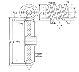
Figure: Dimension of Worm Gear
The basic dimensions of the worm and the worm wheel are shown in Fig. 2.1. For an involute helicoidal tooth form,


Where,
ha1 = addendum (mm)
hf1= dedendum (mm)
c = clearance (mm)
The outside and root diameters of the worm are expressed as follows:


where
da1 = outside diameter of the worm (mm)
df1 = root diameter of the worm (mm)
The addendum and dedendum of the worm wheel at throat can be expressed as


Where,
ha2 = addendum at the throat (mm)
hf2 = dedendum in the median plane (mm)
The dimensions of the worm wheel are as follows:


Where,
da2 = throat diameter of the worm wheel (mm)
df2 = root diameter of the worm wheel (mm)
The effective face width (F) of the worm wheel is given by

The length of the root of the worm wheel teeth (lr) is given by

Key Takeaways:
For gear tooth proportions, the addendum, dedendum and throat diameter plays very important role and there formulas are quite important.
A mechanical spring may be defined as an elastic body whose primary function is to deflect under the action of load (or to absorb energy) and to recover its original shape and removal of load. Spring can be used to measure forces as in spring balances and engine indicators Spring can be used to apply forces as in brakes, clutches and spring –loaded valve.
5.2.1 Stress in helical spring:
Consider a helical compression spring of circular wire subjected to an axial load W
D=mean diameter of the spring
d =diameter of the spring wire
n =number of active coils
G= modulus of rigidity for the spring material
W=axial load
Ϡ= maximum shear stress induced in the wire,
L= spring index= D/d
P=Pitch of the coils, and θ=deflection of the spring
A couple W×D/2 is cutting on wire, to balance it an equal couple T= W×D/2has to be there.
T=W×D/2=π/16×Ϡ1×d13
Ϡ1=8WD/π d3
Ϡ1 is the stress induced in the wire due to twisting moment T generated by the load W.
5.2.2 Deflection of helical compression and expansion spring:
Total active length of the wire:
l =length of one coil ×number of active coil
= πD×n
Θ=angular deflection of the wire when acted upon by the torque T
Axial deflection of the spring,
Delta=θ×D/2=θ×R
We know that,
T/J=Ϡ/R=Gθ/l
Where, J=polar moment of inertia of the spring wire.
=π/32d4
d =diameter of wire, and G=modulus of rigidity for the material of the spring wire.
Now, θ=Tl/GJ =((W×D/2)πD.n)/(G×π/32d4)
=16WD3.n/Gd4
Substituting the value of θ in equation (1), we get
=16WD2.n/Gd4 ×D/2
=8WD3n/Gd4=8WC3n/Gd
And, the stiffness of the spring or spring rate, K=W/delta=Gd4/8D3.n= Constant
5.2.3 Spring subjected to fatigue loading:
The helical spring subjected to fatigue loading are designed by using Soderberg line method. The spring material generally tested for shear stress generated by torsional moment which is repeated in nature.
5.2.4 Concentric and helical torsion spring:
These springs may be of helical or spiral type. Helical type is used where applied load tend to wind up or wrap up the spring. Spiral type is also used where the loads tends to increase the number of coils. Spiral spring is used in watches and clocks.
The major stresses produced in torsion springs are tensile and compressive due to bending.
5.2.5 Critical frequency of spring:
When one end of a spring is displaced rapidly, a wave called a spring surge travels down the spring. If the other end is fixed,the wave can reflect back. If the wave frequency is near the natural frequency of the spring, resonance may occur resulting in extremely high stresses. Catastrophic failure may occur, as shown in this valve-spring from an overrevved engine.
The governing equation is the wave equation:
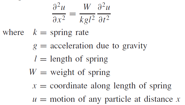
The solution to this equation is harmonic and depends on the given physical properties as well as the end conditions. The harmonic, natural, frequencies for a spring placed between two flat and parallel plates, in radians per second, are

In cycles per second, or hertz,

With one end against a flat plate and the other end free

The weight of a helical spring is

The fundamental critical frequency should be greater than 15 to 20 times the frequency of the force or motion of the spring. If necessary, redesign the spring to increase k or decrease W.
5.2.6 Design of an automotive leaf spring:
A spring leaf commonly used in automobiles is of a semi-elliptical form. It is built up of a number of plates known as leaf. These leaves are usually given an initial curvature or cambered so that they will tend to straighten under the load. The leaves are held together by means of a band shrunk around them at the centre or by a bolt passing through the centre. Since the band exerts stiffening and strengthening effect, therefore the effective length of the spring for bending will be overall length of the spring minus width of band.
In case of centre bolt, two-third distance centres of U-bolt should be subtracted from the overall length of the spring in order to find effective length. The spring is clamped to the axle housing by means of U-bolts.
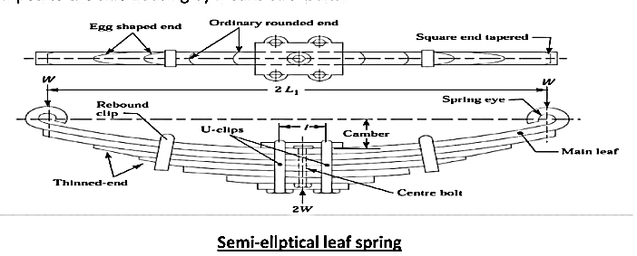
The longest leaf is known as main leaf or a master leaf has its end formed in the shape of an eye through which the bolts are passed to secure the spring to support. Usually the eyes through which the spring is attached to the hanger or shackle are provided with the bushings of some antifriction material such as bronze rubber. The other leaves of the spring are known as graduated leaves. In order to prevent digging in the adjacent leaves, the ends of graduated leaves are trimmed in various forms.
Since the master leaf has to withstand the vertical bending loads as well as sideways of the vehicle, therefore due to the presence of stresses caused by this loads, it is usual to provide two full length leaves and rest of graduated leaves.
References
