Module – 03
CAMS
A cam is a rotating machine element which gives reciprocating or oscillating motion to another element known as follower.
Types of Cams:
Cams can be classified according to:
3.2.1. Classification of Cam
Though the cams may be classified in many ways, among them we can classified:
1. Radial or disc cam.
2. Cylindrical cam
1. Radial or disc cam: In radial cams, the follower reciprocates or oscillates in a direction perpendicular to the cam axis. The cams as shown in Fig.3.1. are all radial cams.
Example: Radial or disc cam.
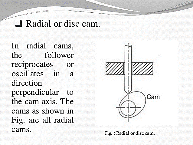
Fig.3.1. Radial or disc cam
2. Cylindrical cam:
In cylindrical cams, the follower reciprocates or oscillates in a direction parallel to the cam axis. The follower rides in a groove at its cylindrical surface. A cylindrical grooved cam with a reciprocating and an oscillating follower is shown in Fig.3.2.
Example: Cylindrical cam.
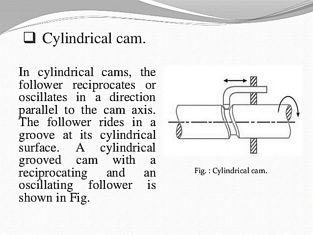
Fig.3.2. Cylindrical cam
3.2.2. Classification of cams-followers:
1. Knife edge follower: When the contacting end of the follower has a sharp knife edge, it is called a knife edge follower, as shown in Fig.3.3.
Example: Cam with knife edge follower.
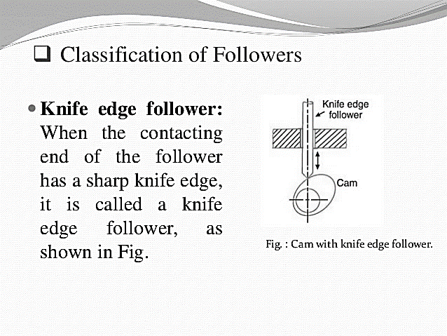
Fig.3.3. Cam with knife edge follower.
2. Roller follower: When the contacting end of the follower is a roller, it is called a roller follower, as shown in Fig.3.4.
Example: Cam with Roller follower.
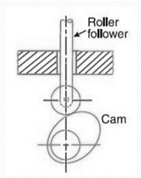
Fig.3.4. Cam with Roller follower
3. Flat faced follower: When the contacting end of the follower is perfectly Flat faced, it is called a Flat faced follower, as shown in Fig.3.5.
Example: Cam with Flat faced follower.
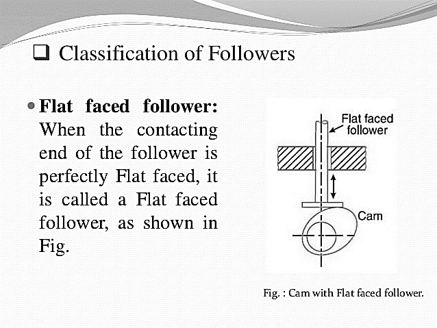
Fig.3.5. Cam with Flat faced follower
4. Spherical faced follower: When the contacting end of the follower is of spherical shape, it is called a spherical faced follower, as shown in Fig.3.6.
Example: Cam with Spherical faced follower.
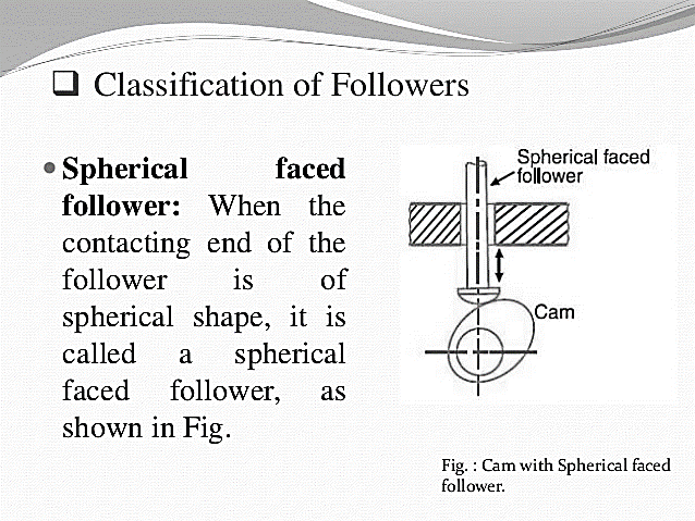
Fig.3.6. Cam with Spherical faced follower.
5. Off-set follower: When the motion of the follower is along an axis away from the axis of the cam center, it is called off-set follower.
Example: Cam with off-set follower.
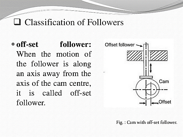
Fig.3.7. Cam with off-set follower
Key takeaways:
Nomenclature of cams:
• Cam Profile: The contour of the working surface of the cam.
• Trace Point: The point at the knife edge of a follower, or the center of a roller, or the center of a spherical face.
• Pitch Curve: The path of the tracer point.
• Base Circle: The smallest circle drawn, tangential to the cam profile, with its center on the axis of the cam shaft. The size of the base circle determines the size of the cam.
• Prime Circle: The smallest circle which can be drawn from the center of the cam and tangent to the pitch curve.
• Prime circle radius: Prime circle radius is the sum of Base circle radius along with radius of roller for roller follower.
• Pressure Angle: The angle between the normal to the pitch curve and the direction of Motion of the follower at the point of contact.
• Lift of stroke: It is the maximum travel of the follower from its lowest position to the topmost position. The maximum rise is called lift.
• Pitch Point: It is a point on the curve having maximum pressure angle.
• Pitch Circle: It is the circle drawn from the center of the cam through the pitch points.
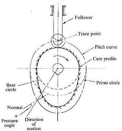
Fig.3.8. Nomenclature of cam profile
Cam followers can be classified according to:
3.3.1. Classifications of followers according to shape-
3.3.2. Classifications of followers according to movement:
1. Reciprocating follower-
In this type, as the cam rotates, the follower reciprocates or translates in the guides.
2. Oscillating follower-
The follower is pivoted at a suitable point on the frame and oscillates as the cam makes rotary motion.
3.3.3. Classifications of followers according to line of movement:
1. Radial follower-
The follower is known as a radial follower if the line of movement of the follower passes through the center of rotation of cam.
2. Offset follower-
If the line of movement of follower is offset from the center of rotation of the cam, the follower is known as an offset follower.
Key takeaway:
Cam followers can be classified according to:
The cam motion or profile:
The motion of the cam follower depends upon the profile or shape of the cam. Therefore, the profile determines the resultant action. Cams are expensive to make and therefore the cam follower is normally sacrificial - allowed to wear.
There are three types of cam profile:
• Uniform Velocity
• Uniform acceleration and retardation
• Simple Harmonic Motion
3.4.1. Cam with radial roller follower Cam Profile:
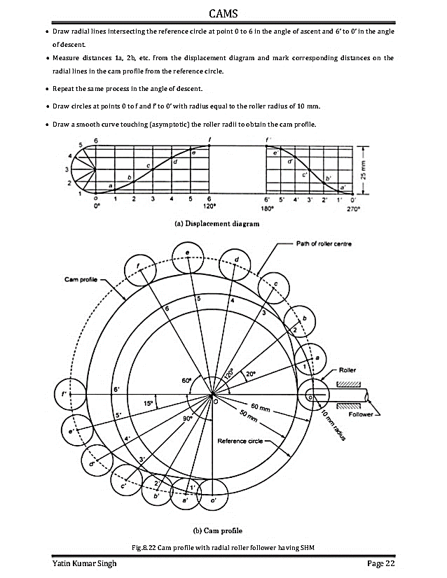
Fig.3.9. Cam profile with radial roller follower
3.4.2. Offset Roller Follower:
A cam profile with offset roller follower is shown in Fig.3.10.
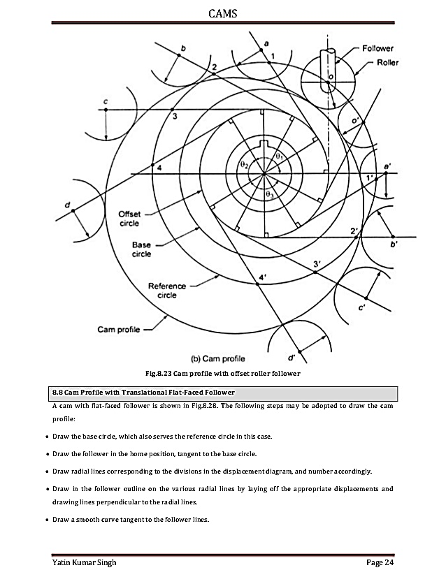
Fig.3.10. offset radial cam profile
The following steps may be used to draw the cam profile:
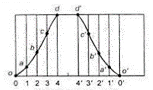
Fig.3.11. Displacement diagram
Key takeaway:
When the follower moves with the specified motion, the shape of the cam profile thus obtained is difficult and costly to manufacture.
• So, cams with specified contours are specified and motion of follower is determined.
• Cam profiles consisting of circular arcs and straight lines are preferred.
3.5.1. Tangent Cam with reciprocating roller follower tangent cam:
• Flanks of the cam are straight and tangential to the base circle and nose circle.
• Used for operating inlet and exhaust valve of IC Engines.
Tangent cam with reciprocating roller follower tangent cam:
Two cases for derivation of displacement, velocity and acceleration expressions:
1. When the roller has contact with the straight flanks
2. When the roller has contact with the nose.
Let,
 Radius of the base circle or minimum radius of the cam,
 Radius of the roller,
 Radius of nose,
= Semi-angle of action of cam or angle of ascent,
Θ = Angle turned by the cam from the beginning of the roller displacement
Φ = Angle turned by the cam for contact of roller with the straight flank, and
ω = Angular velocity of the cam.
CASE 1: When the roller has contact with straight flank displacement:
Let the cam has turned through an angle* θ (less than ϕ) for the roller to have contact at any point (say F) between the straight flanks EG. The centre of roller at this stage lies at C. Therefore displacement (or lift or stroke) of the roller from its lowest position is given by
Displacement


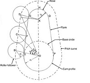
Fig.3.12. When the roller has contact with straight flank displacement
Velocity is given by: -
Differentiating equation (i) with respect to t, we have velocity of the follower,


Velocity is maximum where θ maximum
This happens when roller just leaves the contact with the straight flank at G i.e. when  .
.

Acceleration is given by: -
Now differentiating equation with respect to t, we have acceleration of the follower,


Therefore;
When θ=0° i.e. when the roller is at the beginning of its lift along the straight flank (or when the roller has contact with the straight flank at E).
∴ Minimum acceleration of the follower,

The acceleration is maximum when θ=ϕ i.e. when the roller just leaves contact with the straight flank merges into a circular nose.
∴ Maximum acceleration of the follower,

CASE 2: When the roller has contact with the nose displacement:
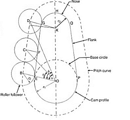
Fig.3.13. Roller has contact with nose displacement
The displacement of the roller is given by

Substituting  and
and  we have


Now from right angles triangles OAK and DAK,


Squaring both sides,


∴ 
Substituting the value of  in equation we get

Velocity: -
Differentiating equation with respect to t, we have velocity of the follower,


Acceleration: -
Now differentiating equation with respect to t, we have acceleration of the follower,

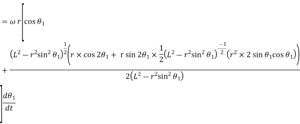
Substituting  and multiplying the numerator and denominator of second term by
  , we have


Key takeaway point:
Velocity is given as:

Acceleration is given by:

2. When the roller has contact with the nose displacement:
Velocity is given by:

Acceleration is given by:

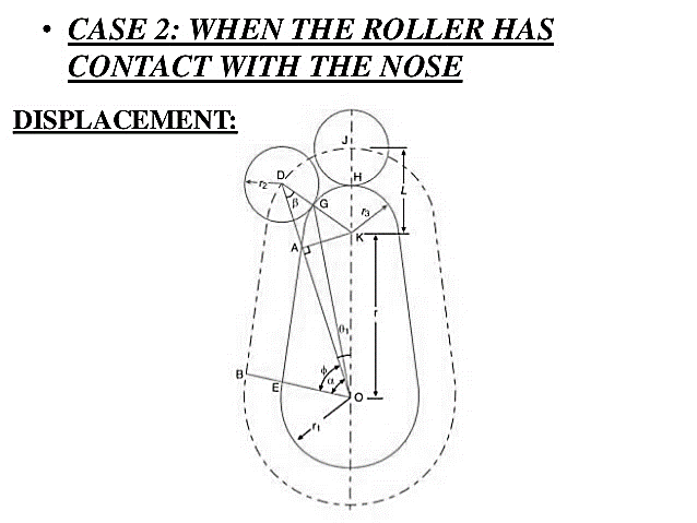
Fig.3.14. Circular arc cam with flat faced follower
Let

 Nose circle radius
 Flank circle radius
 Distance between centre of radius and nose circles.
 Angle of ascent
Φ= Angle of contact on circular flank
Displacement : 


Velocity-


From this equation, it is evident that, at the beginning of the ascent, the velocity is zero (when θ=0) and it increases with θ. It will be maximum when the follower is just shift from circular flank to circular nose.

Acceleration-


It is obvious from the above equation that at the beginning of the ascent when θ=0, acceleration is maximum and it goes on decreasing and is maximum when θ=ϕ


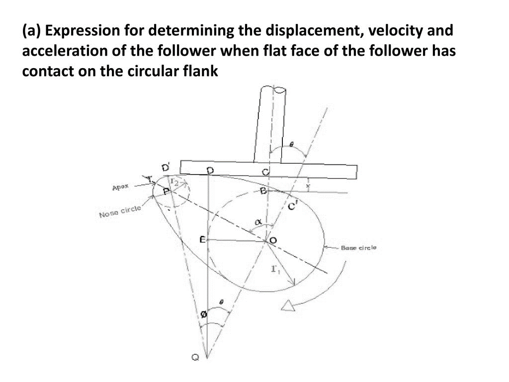
Fig.3.15. Circular arc cam with flat faced of the follower has contact on the nose
Let
 Least base circle radius
 Nose circle radius
 Flank circle radius
 Distance between centres of cam and nose circles
 Angle of ascent
 Angle of contact on circular flank
Displacement 


Velocity-


The velocity is minimum when  This happens when follower is at the apex of circular nose and it is maximum when
  is maximum and it is so when the contact changes from circular flank to circular nose i.e.
Acceleration-


Negative sign indicates retardation. It is maximum when  i.e., when the follower is at the apex of the nose and minimum
  is maximum i.e., when the follower changes contact from circular flank to circular nose.


It may be noted that as the contact between cam and follower passes through point D, the acceleration of the follower suddenly changes from  i.e., sudden change from positive acceleration to negative acceleration (retardation).
Key takeaway:
Velocity is given as-

Acceleration is given as-

2. Determining the displacement, velocity and acceleration of the follower when flat face of the follower has contact on the nose.
Velocity is given as-

Acceleration is given as-

References: