Back to Study material
MT

Unit - 1

Tooling for conventional and non-conventional machining processes


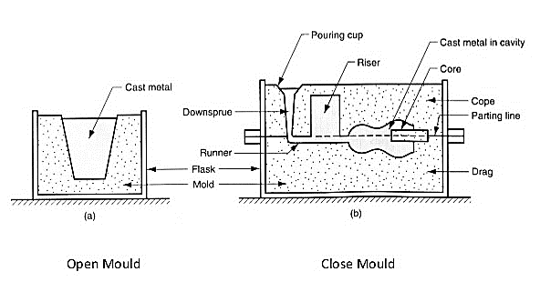
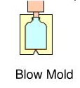
  • A mould is a hollowed-out block that is filled with a liquid like plastic, glass, metal, or ceramic raw materials. The liquid hardens or sets inside the mould, adopting its shape. A mould is the counterpart to a cast.
  • Mould or Mould cavity contains molten metal and is essentially a negative of the final product.
  • Mould is obtained by pattern in moulding material (sand).
  • Mould material should possess refractory characteristics and withstand the pouring temperature.
  • Types of moulding:

  • Hand moulding- This moulding is used for odd castings generally less than 50 no. and ramming is done by hands which takes more time.
  • Machine moulding- This moulding is used for simple castings to be produced in large numbers. Ramming is done by machine so require less time.
  • Bench moulding- This moulding is done on a bench of convenient height to the moulder and is used for small castings.
  • Floor moulding- This moulding is done on the foundry floor and is used for all medium and large castings.
  • Pit moulding- This moulding is done in a pit which act as drag and is used for very large castings.
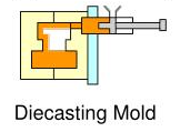
  • Die & Mold is the tool used to produce large quantities of same products.
  • Automobile, television and home appliances are produced by Die & Mold.
  •  

    Cutting Tools:

    • One of most important components in machining process

    • Performance will determine efficiency of operation

    • Two basic types (excluding abrasives):

             Single point and multiple point

    • Must have rake and clearance angles ground or formed on them

    Cutting-Tool Materials:

    • Tool bits generally made of seven materials: -

  • High-speed steel:
  • It may contain combinations of tungsten, chromium, vanadium, molybdenum, cobalt.
  • Can take heavy cuts, withstand shock and maintain sharp cutting edge under red heat.
  • Generally, two types (general purpose)
  • 1)     Molybdenum-base (Group M)

    2)     Tungsten-base (Group T)

  • Cobalt added if more red hardness desired.
  • 2.     Cast alloys (such as stellite):

  • Usually contain 25% to 35% chromium, 4% to 25% tungsten and 1% to 3% carbon.
  • Qualities:
  • 1)     High hardness

    2)     High resistance to wear

    3)     Excellent red-hardness

  • Operate 2 ½ times speed of high-speed steel
  • Weaker and more brittle than high-speed steel
  • 3.     Cemented carbides

  • First used in Germany during WW II as substitute for diamonds.
  • Various types of cemented (sintered) carbides developed to suit different materials and machining operations.
  • Good wear resistance.
  • Operate at speeds ranging 150 to 1200 sf/min.
  • Can machine metals at speeds that cause cutting edge to become red hot without losing harness.
  • 4.     Ceramics

    5.     Cermet’s

    6.     Cubic Boron Nitride

    7.     Polycrystalline Diamond


    Jigs and Fixtures:

  • Some machining operations are so simple’ which are done quite easily, such as turning, the job is held in position in the chuck and turning operation is done easily. No other device is required to hold the job or to guide the tool on the machine in such an operation. But some operations are such type in which the tool is required to be guided by means of another device and also some jobs are of such forms which are required to be held in position on the machine by means of another device.
  • The device which guides the tool is called jig and the device which holds the job in position is called fixture.
  • Jigs and fixtures are special purpose tool which are used to facilitate production (machining, assembling and inspection operations), when work piece is based on the concept of interchangeability according to which every part will be produced within an established tolerance. Jigs and fixtures provide on means of manufacturing interchangeable parts since they establish a relation with predetermined to tolerance between the work and cutting tool. They eliminate the necessity of a special set up for each individual park. So’ A jig is may be de-fined as a device which hold and position the work; locate or guides the outing tool relative to the work piece and usually not fixed to the m/c table. It is usually lightly in construction.                                                                                                                  
  • A fixture is a work holding device and position the work; but doesn’t guide ‘locate or position the cutting tool’ the setting of the tool is done by machine adjustment and a setting blocker using slip gauges. A fixture is hold or clamp-ed to the machine table. It is usually heavy in construction. Jigs are used on drilling, reaming, tapping and couter boring operations, while fixtures are used in connection with turning, milling, grinding, shaping, planning and boring operations.
  • The use of jig and fixture makes possible more rapid and more accurate manufacturing at a reduction of cost.
  •  

    Uses of Jigs and Fixtures:

  • Jigs and fixtures are used to reduce the cost of production as there use elimination being out work and setting up of tools.
  • To increase the production.
  • To assure the high accuracy of the parts.
  • To provide for interchangeability.
  • To enables heavy and complex shaped parts to be machined by holding rigidly to a machine.
  • To control quality control expenses.
  • Less skilled labor.
  • Saving labor.
  • There use partially automates the machine tool.
  •  

    Purpose of Using Fixtures and Jigs

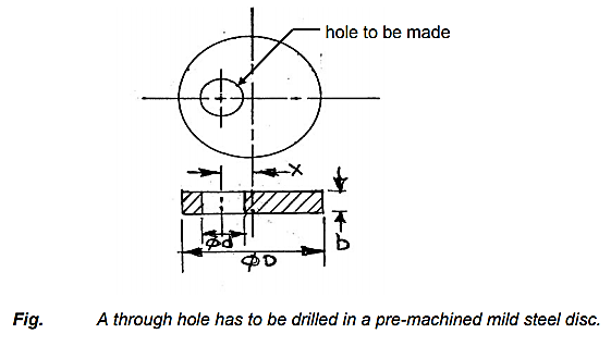
  • For a machining work, like drilling a through hole of given diameter eccentrically in a pre-machined mild steel disk, in a conventional drilling machine without using any fixture or jig, the following elementary steps are to be sequentially followed:
  • Cleaning and deburring the blank (disc).
  • Marking on the blank showing the location of the hole and its axis on the blank.
  • Punch the center at the desired location and prick punch the periphery of the hole to be made in the disc
  • Mount the blank in a drilling vice using parallel block, a small Vee block etc. to provide support and clamp the blank firmly.
  • Position the vice along with the marked blank to bring the hole axis in alignment with the drill axis by
  •       Either adjusting the vise position w.r.t. the fixed drill axis.

          Or moving the drilling machine table and then locking the table position.

          Or moving the radial arm and the drilling head, if it is a radial drilling machine.
  • After fixing the blank, vise and the table, alignment is checked again
  • If error, like eccentricity, is found to occur then readjustment of location of the hole – axis is to be done before and even after starting drilling
  • Drilling is accomplished.
  • Fig. A through hole has to be drilled in a pre-machined mild steel disc

  • Therefore, it appears that so many operations are needed to be carried out carefully and skillfully by the machinist or operator for such a simple job. Even after that there may be inaccuracies in machining. Such tedious and time-consuming manual work are eliminated or drastically reduced in mass production by automatic or special purpose machine tools. But such machine tools are quite expensive and hence are economically justified for only huge or mass production and not viable for small lot or batch production. For batch production proper design and use of simple but effective jigs and fixtures are appropriate and economically justified.
  • The basic purposes of developing and using suitable jigs and fixtures for batch production in machine shops are:
    • To eliminate marking, punching, positioning, alignments etc.
    • Easy, quick and consistently accurate locating, supporting and clamping the blank in alignment of the cutting tool
    • Guidance to the cutting tool like drill, reamer etc.
    • Increase in productivity and maintain product quality consistently
    • To reduce operator’s labor and skill – requirement
    • To reduce measurement and its cost
    • Enhancing technological capacity of the machine tools
    • Reduction of overall machining cost and also increase in interchangeability.
  •  

    Important Considerations While Designing Jigs and Fixtures

  • Designing of jigs and fixtures depends upon so many factors. These factors are analyzed to get design inputs for jigs and fixtures. The list of such factors is mentioned below:
  • (a) Study of workpiece and finished component size and geometry.

    (b) Type and capacity of the machine, its extent of automation.

    (c) Provision of locating devices in the machine.

    (d) Available clamping arrangements in the machine.

    (e) Available indexing devices, their accuracy.

    (f) Evaluation of variability in the performance results of the machine.

    (g) Rigidity and of the machine tool under consideration.

    (h) Study of ejecting devices, safety devices, etc.

    (i) Required level of the accuracy in the work and quality to be produced.
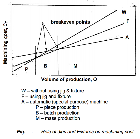
    Fig. Role of jigs and fixtures on machining cost


    W- without using jig and fixture

    F – using jig and fixture

    A – automatic (special purpose) machine

    P – piece production

    B – Batch production

    M – Mass production


    Design of Jigs

  • Elements of Jig
  • Jig generally consists of locating element, clamping element and tool guiding or setting element.

  • Locating Elements
  • Locating elements position the workpiece accurately with respect to tool guiding elements in the jig.

  • Clamping Elements
  • Clamping elements hold the workpiece securely in the located position during operation.

  • Tool Guiding Elements
  • Tool guiding elements help in guiding the tools in correct position with respect to the workpiece. Drill bushes guide the drills accurately to the workpiece

    Design Consideration in Jigs

    (a) The main frame of jig must be strong enough so that the deflection of jig is as minimum as possible. This deflection of jig is caused due to the forces of cutting, clamping of the workpiece or clamping to the machine table. The mainframe of the jig should have the mass to prevent vibration and chatter.

    (b) Frames should be built from simple sections so that frames can be fastened with screws or welded, whenever necessary. Those parts of the frame that remain intact with the jig may be welded. The parts needing frequent changing may be held with the screws. Where the body of jig or fixture has complex shape, it may be cast from good grade of cast iron.

    (c) Clamping should be fast enough and require least amount of effort.

    (d) Clamps should be arranged so that they are readily available and may be easily removed.

    (e) Clamps should be supported with springs so that clamps are held against the bolt head wherever possible.

    (f) If the clamp is to swing off the work, it should be permitted to swing as far as it is necessary for removal of the workpiece.

    (g) All locators, clamps should be easily visible to the operator and easily accessible for cleaning, positioning or tightening.

    (h) Provision should be made for easy disposal of chip so that storage of chips doesn’t interfere with the operation and that their removal during the operation doesn’t interfere with the cutting process.

    (i) All clamps and support points that need to be adjusted with a wrench should be of same size. All clamps and adjustable support points should be capable of being operated from the fronts of the jig.

    (j) Workpiece should be stable when it is placed in jig. If the workpiece is rough, three fixed support points should be used. If workpiece is smooth, more than three fixed support points may be used. Support point should be placed as farthest as possible from each other.

    (k) The three support points should circumscribe the center of gravity of the workpiece.

    (l) The surface area of contact of support should be as small as possible without causing damage to the workpiece. This damage is due to the clamping or work forces.

    (m) Support points and other parts are designed in such a way that they can be easily replaced on failure.

    Fixture

  • Fixture is a workpiece-locating and holding device used with machine tools. It is also used in inspection welding and assembly. Fixture does not guide the cutting tool, but is always fixed to machine or bench. By using fixture, responsibility for accuracy shifts from the operator to the construction of machine tool.
  • When a few parts are to be machined, workpiece clamp to the machine table without using fixture in many machining operations. However, when the numbers of parts are large enough to justify its cost, a fixture is generally used for holding and locating the work.
  • Design Consideration in Fixtures

    (a) The main frame of fixture must be strong enough so that deflection of the fixture is as minimum as possible. This deflection of fixture is caused because of forces of cutting, clamping of the workpiece or clamping to the machine table. The main frame of the fixture should have the mass to prevent vibration and chatter.

    (b) Frames may be built from simple sections so that frames may be fastened with screws or welded whenever necessary. Those parts of the frame that remain permanently with the fixture may be welded. Those parts that need frequent changing may be held with the screws. In the situation, where the body of fixture has complex shape, it may be cast from good grade of cast iron.

    (c) Clamping should be fast enough and require least amount of effort.

    (d) Clamps should be arranged so that they are readily available and may be easily removed.

    (e) Clamps should be supported with springs so that clamps are held against the bolt head wherever possible.

    (f) If the clamp is to swing off the work, it should be permitted to swing as far as it is necessary for removal of the workpiece.

    (g) All locator’s clamps should be easily visible to the operator and easily accessible for cleaning, positioning or tightening.

    (h) Provision should be made for easy disposal of chip so that storage of chips doesn’t interfere with the operation and that their removal during the operation doesn’t interfere with the cutting process.

    (i) All clamps and support points that need to be adjusted with a wrench should be of same size. All clamps and adjustable support points should be capable of being operated from the fronts of the fixture.

    (j) Workpiece should be stable when it is placed in fixture. If the workpiece is rough, three fixed support points should be used. If workpiece is smooth, more than three fixed support points may be used. Support point should be placed as farthest as possible from each other.

    (k) The three support points should circumscribe the center of gravity of the workpiece.

    (l) The surface area of contact of support should be as small as possible without causing damage to the workpiece. This damage is due to the clamping or work forces.

    (m) Support points and other parts are designed in such a way that they may be easily replaced if they break.

    Types of Fixture and Its Industrial Applications

    Vise Fixture
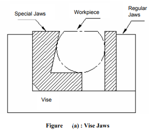
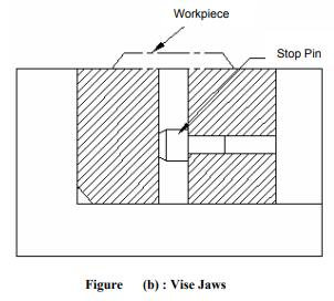
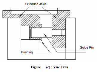
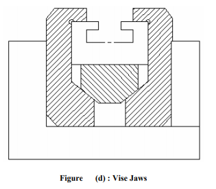
  • It is easy to clamp workpiece with regular shape and parallel sides in a vise. However, workpieces with round or irregular shapes are very difficult to clamp properly. Hence, special jaws are created to hold workpieces with irregular shape properly and at the same time, it also avoids damage to the important surfaces. Various types of vise fixture are shown in Figures (a), (b), (c), (d) and (e).
  • Figure (a) shows simple pair of jaws Design of Fixture for holding round workpiece. Figure (b) shows pair of jaws for holding a thin sheet of non-magnetic material. Stop pin is used to prevent bending of the workpiece by the application of clamping force.
  • Extended jaws for large workpieces are shown in Figure (c). Here guide pins are used to secure alignment. When it is necessary to hold the workpiece firmly in all the directions, wedge type jaws are useful. This arrangement is shown in Figure (d). If the pressure exerted by the cutting tool is likely to tilt upward one end of the workpiece, then the link construction as shown in Figure (e) should be used. It is suitable for rough casting and forging because it permits considerable variation in dimensions of workpiece.

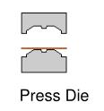
  • Press working has been defined as a chip less manufacturing process by which various components are made from sheet metal.
  • Press working operations are carried out with the help of a metal forming machine called press which shears or forms the component by applying force.
  • The main features of the press include a frame which supports a ram or a slide, a bed and source of power with a mechanism for operating the ram inline or at right angles to the bed.
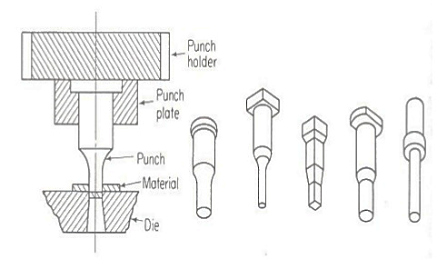
  • The ram is equipped with a punch or a set of punches which have the shape of the job to be produced while a die block is attached to the bed.
  • Workpieces are produced or formed as the punch descends onto the die block. 
  • Processed sheet metal components find extensive industrial and household applications such as in manufacture of automobile and aircraft bodies, office appliances, kitchen ware, storage cabinets, furniture items, mechanical toys etc. 
  • Press tool operation of sheet metal is by far the cheapest and fastest method of complete manufacture of components

  • Punch Design

  • The punch must withstand the maximum blanking or piercing pressure.
  • They should not deflect during operation.
  • Deflection of punches may be avoided by making the body diameter of punch larger than cutting diameter.
  • Small punches may require punch support to prevent breakage
  • Punch plates serve to hold, position and strengthen the punch.
  • Piercing punches should not be smaller in diameter than the thickness of the stock they are to pierce.
  • Always avoid designing punches that would have more than 4 in. of unguided length.
  • Fig. Punch design


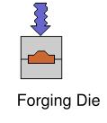
    Die Forging is a manufacturing process involving the shaping of metal using localized compressive forces. Forging is often classified according to the temperature at which it is performed: "cold", "warm", or "hot" forging. Forged parts can range in weight from less than a kilogram to 580 metric tons. Forged parts usually require further processing to achieve a finished part.

    Forging can produce a piece that is stronger than an equivalent cast or machined part. As the metal is shaped during the forging process, its internal grain deforms to follow the general shape of the part. As a result, the grain is continuous throughout the part, giving rise to a piece with improved strength characteristics.

    Types of forging:

  • Open die forging
  • Close Die forging
  •  

  • Open die forging:
  • It involves the shaping of heated metal parts between a top die attached to a ram and a bottom die attached to a hammer anvil or press bed. Metal parts are worked above their recrystallization temperatures-ranging from 1900°F to 2400°F for steel-and gradually shaped into the desired configuration through the skillful hammering or pressing of the work piece.

    2.     Close Die forging:

    It is the forming of complex-shaped parts from a metal semi-product between two engraved tools (dies) by hammering or pressing with a closed-die forging press.

    References:

    1. Kalpakjian and Schmid, Manufacturing processes for engineering materials (5th Edition)-Pearson India, 2014.

    2. Taha H. A., Operations Research, 6th Edition, Prentice Hall of India, 2003.

    3. Shenoy G.V. and Shrivastava U.K., Operations Research for Management, Wiley Eastern,1994.


    Index
    Notes
    Highlighted
    Underlined
    :
    Browse by Topics
    :
    Notes
    Highlighted
    Underlined