Back to Study material
MT

Unit - 2

Metrology


  • A dimension is "a numerical value expressed in appropriate units of measure and indicated on a drawing and in other documents along with lines, symbols, and notes to define the size or geometric characteristic, or both, of a part or part feature".
  • Dimensions - linear or angular sizes of a component specified on the part drawing.
  • Dimensions on part drawings represent nominal or basic sizes of the part and is features.
  • The dimension indicates the part size desired by the designer, if the part could be made with no errors or variations in the fabrication process.
  • Derived from Greek words Such as Metro – Measurement & Logy - Science.
  • BIMP (Bureau of Weights and Measures) – “The Science of Measurement, embracing both experimental & theoretical determinations at any level of uncertainty in any field of science & technology”.
  • Nominal surface – designer’s intended surface contour of part, defined by lines in the engineering drawing.
  • The nominal surfaces appear as absolutely straight lines, ideal circles, round holes, and other edges and surfaces that are geometrically perfect
  • Actual surfaces of a part are determined by the manufacturing processes used to make it.
  • Variety of processes result in wide variations in surface characteristics.
  • Surface finish - a more subjective term denoting smoothness and general quality of a surface.

  • Limits:

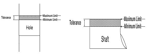
    Limit is nothing but two (upper and lower) extreme permissible sizes between which the actual size is contained.
    Fits:

    It is defined as the degree of looseness or tightness between two mating parts.

    Fit refers to the mating of two mechanical components. Manufactured parts are very frequently required to mate with one another. They may be designed to slide freely against one another or they may be designed to bind together to form a single unit. The most common fit found in the machine shop is that of a shaft in a hole.

    Types of Fits:

    There are three general categories of fits:

    1) Clearance fits for when it may be desirable for the shaft to rotate or slide freely within the hole.

    2) Transition fits for when it is desirable that the shaft to be held precisely, yet not so tightly that it cannot be disassembled, this is usually referred to as a Location or Transition fit.

    3) Interference fits, for when it is desirable for the shaft to be securely held within the hole and it is acceptable that some force be necessary for assembly.

    Clearance Fit:

  • Clearance fit. In this type of fit, the size limits for mating parts are so selected that clearance between them always occur.
  • It may be noted that in a clearance fit, the tolerance zone of the hole is entirely above the tolerance zone of the shaft.
  • In a clearance fit, the difference between the minimum size of the hole and the maximum size of the shaft is known as minimum clearance whereas the difference between the maximum size of the hole and minimum size of the shaft is called maximum clearance.
  • The clearance fits may be slide fit, easy sliding fit, running fit, slack running fit and loose running fit.
  • Interference Fit:

  • In this type of fit, the size limits for the mating parts are so selected that interference between them always occur.
  • It may be noted that in an interference fit, the tolerance zone of the hole is entirely below the tolerance zone of the shaft.
  • In an interference fit, the difference between the maximum size of the hole and the minimum size of the shaft is known as minimum interference, whereas the difference between the minimum size of the hole and the maximum size of the shaft is called maximum interference.
  • The interference fits may be shrink fit, heavy drive fit and light drive fit.
  • Transition Fit:

  • In this type of fit, the size limits for the mating parts are so selected that either a clearance or interference may occur depending upon the actual size of the mating parts. It may be noted that in a transition fit, the tolerance zones of hole and shaft overlap. The transition fits may be force fit, tight fit and push fit.
  • Tolerance:

    It is defined as the difference between maximum limit and minimum limit of the hole or shaft.

    Need of Tolerance:

  • Because of various properties of material, errors are introduced.
  • Change in operator, method, shift etc. also errors in manufacturing.
  • Various machine tools have inherent inaccuracies while manufacturing.
  • Types of Tolerances:

  • Unilateral Tolerance
  • Bilateral Tolerance
  •  

    Unilateral Tolerance:

  • When both limits of size are on the same side of zero line (either +ve or –ve), this type of tolerance are called as unilateral tolerances.
  • Bilateral Tolerance:

  • When one of size is at one side of zero line and other limit of size is at another side of zero line, the tolerance is called as bilateral tolerance.

  • Linear Measurement:

    Linear measurement means measurement between two points or planes. It is basically related with distance between them using line or end standard.  Equipment's for linear measurement are:

  • Non-Precision – Steel Rule – Slip gauge – Caliper and scale – Feeler gauge etc.
  • Precision – Vernier caliper – Vernier height gauge – Vernier depth gauge – Micrometer – Inside micrometer – Depth micrometer
  • Angular Measurement:

    Vernier Bevel protractor:
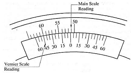
    Fig. Vernier Bevel protractor

  • These are marked 0-60 minutes of arc, so that each division equals 1/12 of 60, that is 5 minutes of arc.
  • These 12 divisions occupy the same space as 23 degrees on the main scale. Therefore, each division of the Vernier is equal to
  • As shown in the main scale is graduated in degrees of arc.
  • The Vernier scale has 12 Divisions each side of the center zero.
  • Optical Instruments for Angular Measurement:

    Autocollimator:

    The instrument is so sensitive that air currents between the optical path and the target mirror can cause fluctuations in the readings.

    An autocollimator is housed inside a sheet-metal or a PVC plastic casing to ensure that air currents do not hamper measurement accuracy.
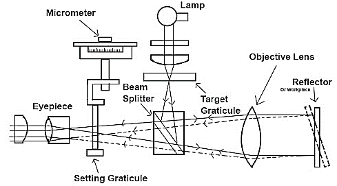
    Fig. Autocollimator
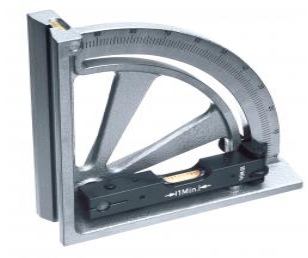
    Clinometers:

  • The clinometers are a special case of the application of the spirit level. It is an instrument used for measuring angle relative to the horizontal plane.
  • A circular scale is provided on the housing. A circular scale is used to measure the angle of inclination of the rotary member relative to the base.
  • The scale may cover the whole circle or only part of it.
  • The base of the instrument is placed on the surface and rotary member is adjusted till zero reading of the bubble is obtained as shown in Fig.
  • The angle of rotation is then noted on the circular scale against an index.
  • It consists of a spirit level mounted on a rotary member carried in a housing.
  • One face of the housing forms the base of the instrument.
  • Clinometers for sale online | Mister Worker™

    Fig. Clinometers

  • Micrometer clinometers is shown in Fig. In this type, one end of spirit level is attached at end of the barrel of a micrometer.
  • The other end of the spirit level is hinged on the base. The base is placed on the surface whose inclination is to be measured.
  • The micrometer is adjusted till the level is horizontal. This type of clinometers is suitable for measuring small angles.
  • The most commonly used clinometers are of the Hilger and Walts type in which circular, scale is totally enclosed and is divided from 0 to 360 at l0' interval. For observation of 10‘-subdivision optical micrometer is provided.

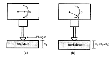
  • Comparator is a precision instrument.
  • Employed to compare the dimension of given component with given standard
  • Employed to find out, by how much the dimensions of the given component differ from that of a known datum.
  • Basic Principle: 

  • Initially, the comparator is adjusted to zero on its dial with a standard job in position.
  • The reading H1is taken with the help of a plunger.
  • Then the standard job is replaced by the work-piece to be checked and the reading H2 is taken.
  • If H1and H2 are different, then the change in the dimension will be shown on the dial of the comparator.
  •  

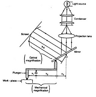
    Mechanical-Optical Comparators:

    Fig. Mechanical-Optical Comparators:


    Principle:

    It works based on fundamental optical law as the edge of the shadow is projected on a curved graduated scale to indicate the comparison measurement.

    Advantages: -

    1. Less friction and inertia effect and higher accuracy

    2. High magnification

    3. Enables readings to be taken irrespective of room lighting conditions


    4. High range and no parallax


    Disadvantages: -

    1. Requires light source

    2. Large and expensive

    3. Inconvenient for continuous use

    4. Instrument setting may drift

    Uses of Comparators:

    Comparators can be used as:

    1. Laboratory Standards

    2. Working Gauges

    3. Final Inspection Gauges

    4. Receiving Inspection Gauges

    5. For Checking Newly Purchased Gauges

    Characteristics:

    1. Robust Design and Construction

    2. Linear Characteristics of Scale

    3. High Magnification

    4. Quick in Results

    5. Versatility

    6. Minimum Wear of Contact Point

    7. Free from oscillations and back lash

    8. Quick Insertion of Work piece

    9. Adjustable table

    10.Compensation from Temperature Effects

    11.Means to Prevent Damage


    When designing a gauge to check a piece of work you need to remember that like he items itself it is impossible to manufacture it to the exact size and form therefore there is also a tolerancing system for gauge design.

    The tolerances and their dispositions for gauges depend on the following:

    1) The nominal size of the product.

    2) The tolerance grade of the product.

    3) The type of gauge e.g., plug, ring Gap etc.
  • Like the tolerancing system for limits and fits where we refer to BS4500 tables, there are tables for gauge design also, the reference tables for these can be found in BS 4500 part 2.
  • Important Points for Gauge Design Points to be considered while designing gauges:

    1. The GO gauges should be replica of the mating parts.

    2. GO gauges, enables several related dimensions to be checked simultaneously.

    3. In inspection, GO gauges must be put into conditions of maximum impassability.

    4. NOT GO gauges check a single element of feature at a time.

    5. In inspection, NOT GO gauges must be put into conditions of maximum possibility.
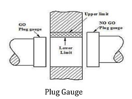
    Fig. GO and NOT GO limits of plug gauge

    Material for Gauges:

  • Hard and wear resistant, corrosion resistant for a prolonged life.
  • Capable of maintaining dimensional stability and form.
  • Low coefficient of expansion.
  • High-carbon steel, Mild steel, Chromium-plated etc.

  • Principle of Interference:

    If two rays of same wavelength meet at some point, mutual interference occurs & natural interference depends on Phase of two waves at their meeting point.

    If two rays are in same phase, then resulting intensity will be the sum of two intensity.

    •If two rays are out of phase, then resulting intensity will be the difference of two intensity.

    •If two rays having same amplitude are out of phase, then resultant will be zero & result will be Dark spot.

    Fig. Two waves of different wavelength, out of [phase by 180 degrees

    •If two rays having same amplitude are in same phase, then resultant will be twice & result will be Bright spot.
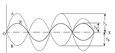
    Fig. Two waves of different amplitude are in same phase


    Tool wear:

    Tool subjected to:

    1. Forces

    2. Temperature

    3. Sliding action

    After continuous use for some time, tool gives unsatisfactory or inefficient performance.

    Unsatisfactory or inefficient performance is due to “Tool Wear or Tool failure”. Consequences:

    1. Loss of dimensional accuracy

    2. Increased surface roughness

    3. Increased power requirement

    4. Excessive vibration and abnormal sound (Chatter)

    5. Total breakage of the tool

    Tool is replaced or reconditioned usually by grinding.

    Tool Wear depending factors:

    1. Type of tool material and its hardness

    2. Type and condition of work piece material

    3. Dimensions of cut (Feed and depth of cut)

    4. Cutting speed

    5. Tool geometry

    6. Tool temperature (function of cutting speed, feed and depth of cut)

    7. Type of cutting fluid

    Classification of Tool Wear

    1. Flank wear

    2. Crater wear on tool face

    3. Localized wear such as the rounding of Cutting edge

    4. Chipping of the cutting edge

    Surface integrity is the study and control of this subsurface layer and the changes in it that occur during processing which may influence the performance of the finished part or product.

    Surface integrity is the study and control of this subsurface layer and the changes in it that occur during processing which may influence the performance of the finished part or product
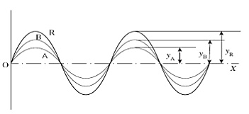
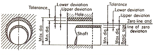
     

    Fig. Problem of selective assembly

    Tolerance Analysis:

  • Identify each of the error sources.
  • Determine the sensitivity of each performance parameter to changes in each error source assuming all other sources are error free.
  • Assuming all error sources are independent of each other, calculate the maximum probable error in each performance parameter.
  • Add a safety margin before using the results in any specification.

  • Machining of micro parts is not literally correct.

    Removal of material in the form of chips or debris having the size in the range of microns.

    Creating micro features or surface characteristics (especially surface finish) in the micro/nano level.

    Definition: material removal at micro/nano level with no constraint on the size of the component being machined.

    Why Micro machining?

  • Final finishing operations in manufacturing of precise parts are always of concern owing to their most critical, labor intensive and least controllable nature.
  • In the era of nanotechnology, deterministic high precision finishing methods are of utmost importance and are the need of present manufacturing scenario.
  • The need for high precision in manufacturing was felt by manufacturers worldwide to improve interchangeability of components, improve quality control and longer wear/fatigue life.
  • Machining Accuracy:

  • The machining processes are classified into three categories on the basis of achievable accuracy viz. Conventional machining, precision machining and ultra-precision machining.
  • Machining accuracies in conventional processes is about 1 μm, while in precision and ultra-precision machining, it is 0.01μm (10 nm) and 0.001μm (1 nm) respectively.
  • As the demand moves from the microtechnology (1μm accuracy capability) to the nanotechnology region (1 nm accuracy) the systems engineering demands rapid increase in stringency and complexity.
  • References:

    1. Kalpakjian and Schmid, Manufacturing processes for engineering materials (5th Edition)-Pearson India, 2014.

    2. Taha H. A., Operations Research, 6th Edition, Prentice Hall of India, 2003.

    3. Shenoy G.V. and Shrivastava U.K., Operations Research for Management, Wiley Eastern,1994.


    Index
    Notes
    Highlighted
    Underlined
    :
    Browse by Topics
    :
    Notes
    Highlighted
    Underlined