Back to Study material
MT

Unit - 4

Unconventional Machining Processes


In Unconventional machining processes, there is no physical contact between the tool and work piece. Although in some non-traditional processes tool wear exists, its rarely is a significant problem.


  • Water Jet Machining (WJM) is a mechanical energy based non-traditional machining process used to cut and machine soft and non-metallic materials.
  • It involves the use of high velocity water jet to smoothly cut a soft workpiece. It is similar to Abrasive Jet Machining (AJM).
  • In water jet machining, high velocity water jet is allowed to strike a given workpiece. During this process, its kinetic energy is converted to pressure energy. This induces a stress on the workpiece. When this induced stress is high enough, unwanted particles of the workpiece are automatically removed.
  • Construction:

  • Water from the reservoir is pumped to the intensifier using a hydraulic pump.
  • The intensifier increases the pressure of the water to the required level. Usually, the water is pressurized to 200 to 400 MPa.
  • Pressurized water is then sent to the accumulator. The accumulator temporarily stores the pressurized water.
  • Pressurized water then enters the nozzle by passing through the control valve and flow regulator.
  • Control valve controls the direction of water and limits the pressure of water under permissible limits.
  • Flow regulator regulates and controls the flow rate of water.
  • Pressurized water finally enters the nozzle. Here, it expands with a tremendous increase in its kinetic energy. High velocity water jet is produced by the nozzle.
  • When this water jet strikes the workpiece, stresses are induced. These stresses are used to remove material from the workpiece.
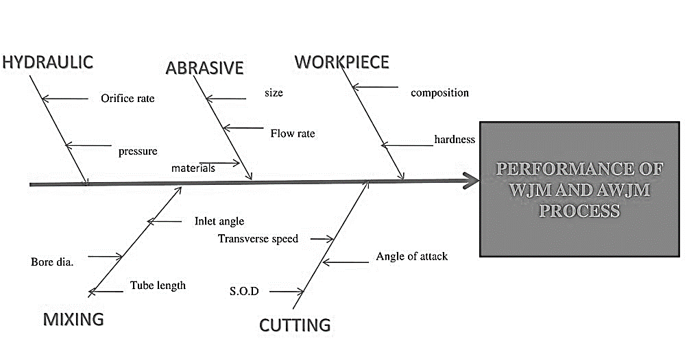
  • Fig. Process Parameters


  • MRR depends on the reactive force F of the jet.
  • Reactive force = Mass flow rate (m) X jet velocity (v)

    Hence,

    MRR α m α v

  • Depends on fluid pressure
  • Depends on fluid pressure (p) and nozzle diameter

  • In AJM, the material removal takes place due to impingement of the fine abrasive particles. These particles move with the high-speed air (or gas) stream.
  • The abrasive particles are typically of 0.025 mm diameter and the air discharges at a pressure of several atmosphere.
  • Working of Abrasive jet machining (AJM):
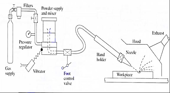
    Fig. Abrasive jet machining

  • The nozzle is made of a hard material like Tungsten Carbide here fine-grained abrasive particles are fed from the Hooper into the mixing chamber.
  • High pressure air is forced in to the mixing chamber.
  • The stream of abrasive particles bombards the work piece at a very high speed and removes the work material due to erosion.
  • The abrasive particle feed rate is controlled by the amplitude of vibration of the mixing chamber.
  • Typical AJM Parameters

  • Abrasive
  • Aluminum oxide for Al and Brass.
  • SiC for Stainless steel and Ceramic
  • Bicarbonate of soda for Teflon
  • Glass bed for polishing.
  •  

    2.     Size

  • 10-15 Micron
  •  

    3.     Quantity

  • 5-15 liter/min for fine work
  • 10-30 liter/min for usual cuts.
  • 50-100 liter/min for rough cuts
  •  

    4.     Medium

  • Dry air, CO2, N2
  • Quantity: 30 liter/min
  • Velocity: 150-300 m/min
  • Pressure: 200-1300 KPa
  • 5.     Nozzle

  • Material: Tungsten carbide
  • Stand of distance: 2.54-75 mm
  • Diameter: 0.13-1.2 mm
  • Operating Angle: 60° to vertical
  •  

    6.     Factors affecting MRR:

  • Types of abrasive and abrasive grain size
  • Flow rate
  • Standoff distance
  • Nozzle Pressure
  • The nozzle is one of the most vital elements controlling the process characteristics. Since it is continuously in contact with the abrasive grains flowing at a high speed, the material must be hard to avoid any significant wear.

    One of the most important factors in AJM is the distance between the work surface and the tip of the nozzle, normally called the nozzle distance
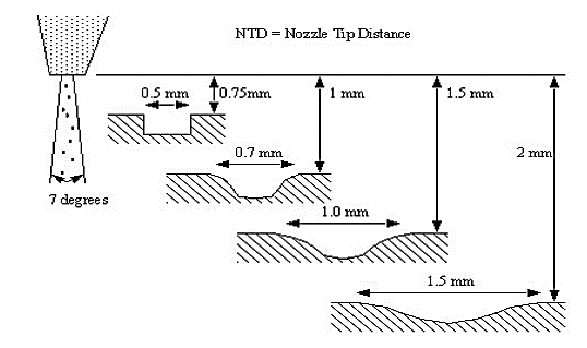
    Fig. Nozzle Tip Distance

    Applications: -

  • For drilling holes of intricate shapes in hard and brittle materials.
  • For machining fragile, brittle and heat sensitive materials.
  • AJM can be used for drilling, cutting, deburring, cleaning and etching.
  • Micro-machining of brittle materials.
  • Limitations: -

  • MRR (Material removal rate) is rather low (around ~ 15 mm^3/min for machining glass).
  • Abrasive particles tend to get embedded particularly if the work material is ductile. Tapering occurs due to flaring of the jet.
  • Environmental load is rather high.
  • Advantages: -

  • Extremely fast setup and programming.
  • No start hole required.
  • There is only one tool.
  • Low capital cost.
  • Less vibration.
  • No heat generation in work piece.
  • Environmentally Friendly.
  • Disadvantages: -

  • Low metal removal rate.
  • Abrasive powder cannot be reused.
  • Tapper is also a problem

  • Principle of Ultrasonic machining (USM):

    In this method with the help of piezoelectric transducer tool is vibrate at high frequency in a direction normal to the surface being machined abrasive slurry are used for the remove the metal from work piece.

    Working of USM:
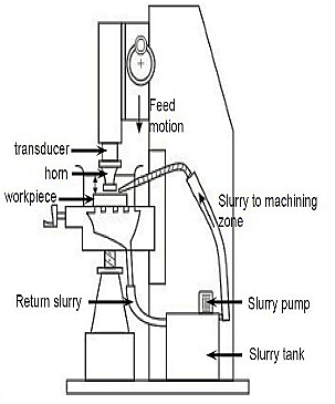
    Fig. Ultrasonic machining

  • The USM diagram shown in figure.
  • In ultrasonic machining a tool vibrate longitudinally at 20 to 30 kHz with amplitude between 0.01 to 0.06 mm is pressed on to the work surface with light force.
  • The electronic oscillator and amplifier are also known as generator.
  • It converts the electrical energy of low frequency to high frequency.
  • At the time high frequency current is passed through the coil therefore change in electromagnetic field which produces longitudinal strain.
  • As the tool vibrate with specific frequency the abrasive slurry mix with water and grain of definite proportion is made to flow under pressure through the tool work piece interface. The flow of slurry through the work tool interface actually causes thousands of microscopic grains to remove the work material by abrasion.
  • Applications: -

  • USM is best suitable for hard, brittle material, such as ceramics, carbides, glass, precious stone etc.
  • Advantages: -

  • Any materials can be machined regardless of their electrical conductivity.  Especially suitable for machining of brittle materials.
  • Machined parts by USM possess better surface finish and higher structural integrity. USM does not produce thermal, electrical and chemical abnormal surface.
  • Disadvantages: -

  • Tool wears fast in USM.
  • Machining area and depth is restraint in USM.
  • High cost of tooling.
  • MMR is low.

  • Principle of EDM:

    Electrical discharge machining (EDM), sometimes also referred to as spark machining, spark eroding, burning, die sinking, wire burning or wire erosion, is a manufacturing process whereby a desired shape is obtained using electrical discharges (sparks).

    Material is removed from the work piece by a series of rapidly recurring current discharges between two electrodes, separated by a die-electric liquid and subject to an electric voltage. One of the electrodes is called the tool-electrode, or simply the "tool" or "electrode", while the other is called the workpiece- electrode, or "workpiece".


    Working of EDM:
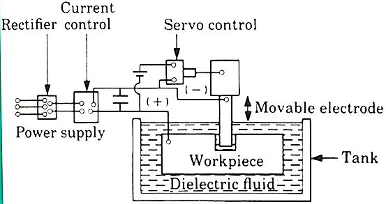
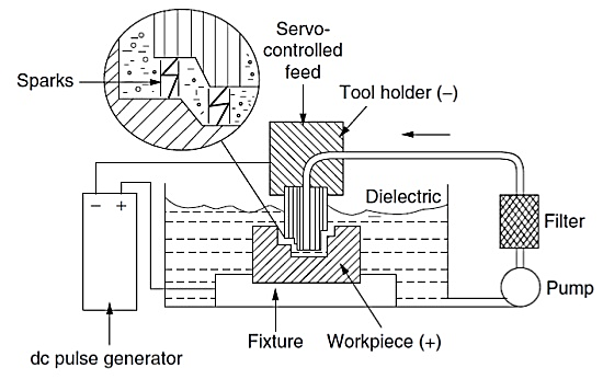
    Fig. Electrical discharge machining


  • The diagram of electro discharge machining shown in figure.
  • EDM is thermal erosion process whereby material is melted and vaporized from an electrically conductive work piece immerse in a liquid dielectric with a series of spark discharge between the tool electrode and the work piece created by a power supply.
  • The electrode and the work piece are separated by a dielectric medium.
  • The dielectric medium is like as kerosene, paraffin or light oil.
  • The strong electrostatic field between the electrode and work piece produce emission of electrons from the cathode.
  • In this gap between tool and work piece get ionized. The liquid is force to sparking zone.
  • Due to high temperature, the metal at the sparking zone melts instantaneously. 
  • The material of the tool is usually a material which conduct electricity and which can be easily shaped.
  • Advantages: -

  • Smaller holes can be easy machined.
  • No contact between tool and work piece then tool life is increase.
  • Any complex shape can be machined.
  • Disadvantages: -

  • Tool life is no longer.
  • Power consumption is high.
  • Cycle time is more

  • Surface finish:

    The outermost boundary of a body adjacent to the air is called surface. When this surface deformed by a sharp cutting edge, the term surface finish describes the boundary.

    A good surface is affected by many variables in single or multiple point machining.

    Surface finish is defined in terms of 4 factors:

  • Roughness – closely spaced surface irregularities, resulting from the manufacturing process or tools.
  • Lay – the overall direction of the roughness pattern which can be affected by the machine and setup.
  • Waviness – longer spaced irregularities caused by machine vibration and material warping among other factors.
  • Flaws – unique surface imperfections in the material or processing.
  • Tool wear:

    Tool subjected to:

    1. Forces

    2. Temperature

    3. Sliding action

  • After continuous use for some time, tool gives unsatisfactory or inefficient performance.
  • Unsatisfactory or inefficient performance is due to “Tool Wear or Tool failure”. Consequences:
  • 1. Loss of dimensional accuracy

    2. Increased surface roughness

    3. Increased power requirement

    4. Excessive vibration and abnormal sound (Chatter)

    5. Total breakage of the tool

    Tool is replaced or reconditioned usually by grinding.

    Tool Wear depending factors:

    1. Type of tool material and its hardness

    2. Type and condition of work piece material

    3. Dimensions of cut (Feed and depth of cut)

    4. Cutting speed

    5. Tool geometry

    6. Tool temperature (function of cutting speed, feed and depth of cut)

    7. Type of cutting fluid

    Classification of Tool Wear

    1. Flank wear

    2. Crater wear on tool face

    3. Localized wear such as the rounding of Cutting edge

    4. Chipping of the cutting edge


    The main components in EDM:

  • Electric power supply
  • Dielectric medium
  • Work piece & tool
  • Servo control unit.
  • The work piece and tool are electrically connected to a DC power supply.
  • The current density in the discharge of the channel is of the order of 10000 A/cm2 and power density is nearly 500 MW/cm2.
  • A gap, known as SPARK GAP in the range, from 0.005 mm to 0.05 mm is maintained between the work piece and the tool.
  • Dielectric slurry is forced through this gap at a pressure of 2 kgf/cm2 or lesser.
  •  

    Working Principle:

  • It is a process of metal removal based on the principle of material removal by an interrupted electric spark discharge between the electrode tool and the work piece.
  • In EDM, a potential difference is applied between the tool and workpiece. 
  • Both tool and work material are to be conductors.
  • The tool and work material are immersed in a dielectric medium.
  • Generally, kerosene or deionized water is used as the dielectric medium.
  • A gap is maintained between the tool and the workpiece.
  • Depending upon the applied potential difference (50 to 450 V) and the gap between the tool and workpiece, an electric field would be established.
  • Generally, the tool is connected to the negative terminal (cathode) of the generator and the workpiece is connected to positive terminal (anode).
  • Fig. EDM Schematic

    Power & Control Circuits:

    Two broad categories of generators (power supplies) are in use on EDM.  Commercially available: RC circuits based and transistor-controlled pulses.

    In the first category, the main parameters to choose from a setup time are the resistance(s) of the resistor(s) and the capacitance(s) of the capacitor(s).

    In an ideal condition, these quantities would affect the maximum current delivered in a discharge.

    Current delivery in a discharge is associated with the charge accumulated on the capacitors at a certain moment.

    Little control is expected over the time of discharge, which is likely to depend on the actual spark-gap conditions.

    Advantage: RC circuit generator can allow the use of short discharge time more easily than the pulse-controlled generator.

    Also, the open circuit voltage (i.e., voltage between electrodes when dielectric is not broken) can be identified as steady state voltage of the RC circuit.

    In generators based on transistor control, the user is usually able to deliver a train of voltage pulses to the electrodes.

    Each pulse can be controlled in shape, for instance, quasi-rectangular.

    In particular, the time between two consecutive pulses and the duration of each pulse can be set.

    The amplitude of each pulse constitutes the open circuit voltage.

    Thus, maximum duration of discharge is equal to duration of a voltage pulse.  Maximum current during a discharge that the generator delivers can also be controlled.

    Details of generators and control systems on EDMs are not always easily available to their user.

    This is a barrier to describing the technological parameters of EDM process.  Moreover, the parameters affecting the phenomena occurring between tool and electrode are also related to the motion controller of the electrodes.

    A framework to define and measure the electrical parameters during an EDM operation directly on inter-electrode volume with an oscilloscope external to the machine has been recently proposed by Ferri et al.

    This would enable the user to estimate directly the electrical parameter that affect their operations without relying upon machine manufacturer's claims.

    When machining different materials in the same setup conditions, the actual electrical parameters are significantly different.

    When using RC generators, the voltage pulses, shown in Fig. are responsible for material removal.
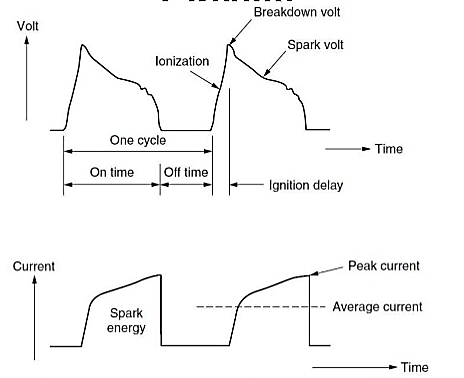
    Fig. Voltage and current waveform during EDM

    Wire EDM:
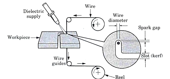
  • This process is similar to contour cutting with a band saw.
  • A slow-moving wire travels along a prescribed path, cutting the work piece with discharge sparks.
  • Wire should have sufficient tensile strength and fracture toughness.
  • Wire is made of brass, copper or tungsten. (About 0.25mm in diameter).
  • Fig. Wire EDM


  • Electrochemical Machining (ECM) is one of the newest and most useful non-traditional machining (NTM) process belonging to Electrochemical category.
  • Electrochemical machining (ECM) is used to remove metal and alloys which are difficult or impossible to machine by mechanical machining process.
  • The reverse of electroplating.
  • This machining process is based Michael Faraday’s classical laws of electrolysis, requiring basically two electrodes, an electrolyte, a gap and a source of D.C power of sufficient capacity.
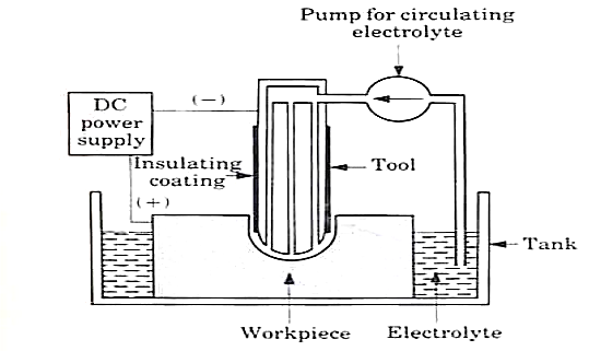
  • Working of ECM:

  • In the actual process of ECM, the cathode is tool shaped (mirror image of work-piece) and anode is the work-piece.
  • A gap (0.05 to 0.7 mm) is provided between the tool and work-piece and electrolyte flows through the gap at a velocity of 30 to 60 m/s and it completes the electrical circuit.
  • Electrolyte is pumped at high pressure of 20 kgf/
    (1.96 MPa) through the gap.
  • Electrolyte must be circulated at a rate sufficiently high to conduct current between them and to carry heat.
  • Metal is removed from the work-piece by dissolution
  • The electric current is of the order of 50 to 40,000 A at 5 to 35 V D.C for current density of 20 to 300 A/
    .
  • Power of 3 KWh is needed to remove 16
    of metal which is almost 30 times the energy required in the conventional process (when the material is readily machinable).
  • Fig. Electro-chemical machining

    Advantages of ECM:

  • Process leaves a burr free surface.
  • Does not cause any thermal damage to the parts.
  • Lack of tool force prevents distortion of parts.
  • Capable of machining complex parts and hard materials.
  • ECM systems are now available as Numerically Controlled machining centers with capability for high production, high flexibility and high tolerances.
  •  

    Types of masks used in Chemical machining:

  • Cut and peel masks.
  • Screen resist masks.
  • Photo resist masks.
  •  

  • Cut and peel maskants:
  • Film of chemically resistant material is applied to the work piece by dipping, spraying or flow coating.
  • Vinyl, styrene and buta diene are used.
  • Rubbery film is then cut & peeled away selectively.
  • Manual scribing of mask material usually achieves an accuracy of ±0.13 mm to ±0.75 mm.
  •  

    2.     Screen resist maskants:

  • Mask material is applied to the work piece surface by printing, using stencils and a fine polyester or stainless-steel mesh screen.
  • Relatively thin coatings with tolerances held to ±0.05 to ±0.18 mm is obtained by screen printing.
  • Etching depths are restricted to about 1.5 mm because of thinness of the coating.
  •  

    3.     Photo resist maskants:

  • Photo resist mask is quite widely used & is often referred to as photochemical machining.
  • Produces intricate & finely detailed shapes using a light activated resist materials.
  • WP coated with photo resist material & a master transparency is held against the WP, while exposure to UV rays takes place.
  • Light activates the photo resist material in those areas corresponding to opaque parts.
  • Tolerances of ±0.025 to 0.005 mm can be produced.
  • The general requirements of tool material in ECM are:

    1. It should be conductor of electricity.

    2. It should be rigid enough to take up the load due to fluid pressure.

    3. It should be chemically inert to the electrolyte.

    4. It should be easily machinable to make it in the desired shape.


    Process Parameter:

    S.no

    Parameters

    Values

    1.

    Power Supply


    Type

    Direct Current


    Voltage

    2 to 35 V


    Current

    50 to 40,000 A


    Current Density

    0.1 A/mm2 to 5 A/mm2

    2.

    Electrolyte


    Material

    NaCl and NaNO3


    Temperature

    20 oC to 50 oC


    Flow rate

    20 lpm/100 A current


    Pressure

    0.5 to 20 bars


    Dilution

    100 g/l to 500 g/l

    3.

    Working gap

    0.1 mm to 2mm

    4.

    Overcut

    0.2 mm to 3 mm

    5.

    Feed rate

    0.5 mm/min to 15 mm/min

    6.

    Electrode material

    Copper, brass and bronze

    7.

    Surface roughness (Ra)

    0.2 to 1.5 μm


    Material removal rate (MRR):

  • Material removal rate (MRR) is an important characteristic to evaluate efficiency of a non-traditional machining process.
  • In ECM, material removal takes place due to atomic dissolution of work material which is governed by Faraday’s laws of Electrolysis.
  • MRR = m / tρ = IA / Fρν

    where m = ItA/Fv = mass of material dissolve

    I = current

    A = Atomic weight

    v = valency

    F = Faraday’s constant = 96500 coulombs

    ρ = density of the material

    Power Supply:

    1. Type: direct current

    2. Voltage: 2 to 35 V

    3. Current: 50 to 40,000 A

    4. Current density: 20 A/cm2 to 300 A/cm2


    Surface finish is defined in terms of 4 factors:

  • Roughness – closely spaced surface irregularities, resulting from the manufacturing process or tools.
  • Lay – the overall direction of the roughness pattern which can be affected by the machine and setup.
  • Waviness – longer spaced irregularities caused by machine vibration and material warping among other factors.
  • Flaws – unique surface imperfections in the material or processing.

  • Laser-beam machining is a thermal material- removal process that utilizes a high-energy, coherent light beam to melt and vaporize particles on the surface of metallic and non- metallic work pieces.

    Lasers can be used to cut, drill, weld and mark. LBM is particularly suitable for making accurately placed holes.

    Principle of Laser beam machining (LBM):

  • Conversion of electrical energy into heat energy to emit laser beam energy.
  • Laser beam is focused on lance then create high energy the high energy concentration on work piece then work piece is melt and vaporized of metal.
  • Working of LBM

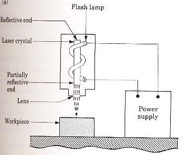
    Fig. Laser Beam Machining

  • The diagram of LBM is shown in figure.
  • Laser is stand for Light Amplification by Simulated Emulsion of Radiation.
  • The work piece is placed on the aluminum work table which material is hard not cut by laser beam.
  • Ruby rod is used into form of cylindrical crystal both ends of ruby rod are finished to optical tolerance.
  • The flash lamp wound around the ruby rod and connected to power supply.
  • The ruby rod becomes highly efficient on low temperature and low efficient on high temperature. It is thus continuous cooled with water, air or liquid nitrogen.
  • When the light beam has been amplified sufficiently and intensity beam of light comes out form partially reflected end it is focused on the work piece at the focused very high temperature which vaporized and removes the metal on work piece.
  • Applications: -

  • LBM can make very accurate holes as small as 0.005 mm in refractory metals ceramics, and composite material without warping the work pieces.
  • It is used for welding of thin metal sheet.
  • Leaser can be used for cutting as well as drilling.
  • Heat treatment.
  • It is used for cutting complex profile.
  • Limitations: -

  • Uneconomic on high volumes compared to stamping.
  • Limitations on thickness due to taper.
  • High capital cost.
  • High maintenance cost.
  • Assist or cover gas required
  •  

    Advantages: -

  • Very hard and abrasive material can be cut.
  • Sticky materials are also can be cut by this process.
  • It is a cost effective and flexible process.
  • High accuracy parts can be machined.
  • No cutting lubricants required.
  • No tool wears.
  • Narrow heat effected zone.
  • No contact between tool and work piece.

  • Plasma Arc Machining is used to remove material from the workpiece. In this process, a high velocity jet of high-temperature gas is used to melt and remove material from the workpiece. This high velocity of hot gas is also known as plasma jet.

    When a gas or air is heated at a temperature of more than 5000 °C, then it will start getting ionized into positive ions, negative ions and neutral ions. When the gas or air is ionized its temperature reaches from 11000 °C to 28000 °C and this ionized gas is called plasma.

    The gas or air is heated with arc and the plasma produced by heating gas is used to remove material from the workpiece. So, the whole process is called Plasma Arc Machining.
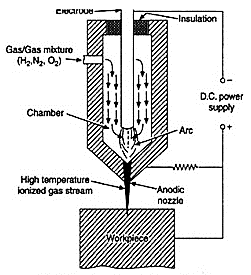
    Fig. Plasma Arc Machining

  • In this case, the high velocity electrons of are collide with the gas molecules & metal to form ionization of beam.
  • The plasma gas is forced through nozzle duct & is made to direct on the work piece to be machined.
  • Much of the heating takes place in duct at about 1600 degree Celsius & metal removal is due to electron bombardment & hot plasma.
  • Mechanism of Metal Removal:

  • The metal removal in PAM is due to high temperature of gases.
  • The heating of work piece is due to direct electron bombardment plus convective heating of hot plasma.
  • The heat produced is sufficient to raise the temperature above its melting point.  Approximately 45% of electrical power delivered to torch is used for removal metal from work piece.
  • PAM is used for cutting, spraying, & surfacing operations.
  •  

    Advantages of Plasma arc Machining:

  • Rapid Cutting Speeds:
  • Plasma arc cutting is faster than oxyfuel for cutting steel up to 50 mm thick and is competitive for greater thickness.
  • Plasma cutting achieves speeds greater than those of laser cutting systems for thickness over 3 mm.
  • The fast-cutting speeds result in increased production, enabling systems to pay for themselves in as little as 6 months for smaller units.
  • 2.     Wide Range of Materials and Thickness:

  • Plasma cutting systems can yield quality cuts on both ferrous and nonferrous metals. Thickness from gauge to 80 mm can be cut effectively.
  • 3.     Easy to Use:

  • Plasma cutting requires only minimal operator training. The torch is easy to operate, and new operators can make excellent cuts almost immediately. Plasma cutting systems are rugged, are well suitable for production environments, and do not require the potentially complicated adjustments associated with laser cutting systems.
  • 4.     Economical:

  • Plasma cutting is more economical than oxyfuel for thickness under 25 mm, and comparable up to about 50 mm. For example, for 12 mm steel, plasma cutting costs are about half those of oxyfuel.
  •  

    Disadvantages of Plasma Arc Machining:

  • The cutter's electrode and nozzle sometimes require frequent replacement which adds to the cost of operation.
  • Non-conductive materials such as wood or plastic cannot be cut with plasma cutters with transferred arc type.
  • Another minor drawback is that the plasma arc typically leaves a 4–6-degree bevel on the cut edge, although this angle is almost invisible on thinner material, it is noticeable on thicker pieces.

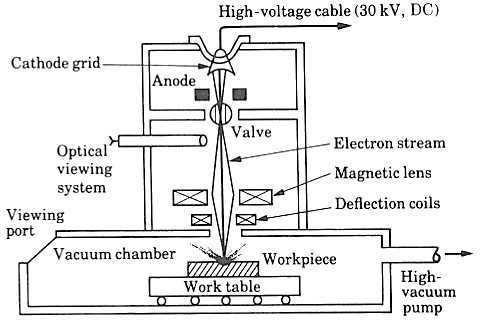
  • Electron Beam Machining (EBM) is a thermal process. Here a steam of high-speed electrons impinges on the work surface so that the kinetic energy of electrons is transferred to work producing intense heating.
  • Depending upon the intensity of heating the work piece can melt and vaporize.
  • The process of heating by electron beam is used for annealing, welding or metal removal.
  • During EBM process very high velocities can be obtained by using enough voltage of 1,50,000 V can produce velocity of 228,478 km/sec and it is focused on 10 – 200 μM diameter.
  • Power density can go up to 6500 billion W/sq.mm. Such a power density can vaporize any substance immediately.
  • Complex contours can be easily machined by maneuvering the electron beam using magnetic deflection coils
  • To avoid a collision of the accelerating electrons with the air molecules, the process has to be conducted in vacuum. So, EBM is not suitable for large work pieces. 
  • Process is accomplished with vacuum so no possibility of contamination.
  • No effects on work piece because about 25- 50μm away from machining spot remains at room temperature and so no effects of high temperature on work
  • Working of EBM

    Fig. Electron Beam Machining

  • The EBM beam is operated in pulse mode.
  • This is achieved by appropriately biasing the biased grid located just after the cathode.
  • Switching pulses are given to the bias grid so as to achieve pulse duration of as low as 50 μs to as long as 15 ms.
  • Beam current is directly related to the number of electrons emitted by the cathode or available in the beam.
  • Beam current once again can be as low as 200μ amp to 1 amp. Increasing the beam current directly increases the energy per pulse.
  • Similarly increase in pulse duration also enhances energy per pulse.
  • High-energy pulses (in excess of 100 J/pulse) can machine larger holes on thicker plates.
  • A higher energy density, i.e., for a lower spot size, the material removal would be faster though the size of the hole would be smaller.
  • The plane of focusing would be on the surface of the work piece or just below the surface of the work piece.
  • Applications: -

  • Used for producing very small size holes like holes in diesel injection nozzles, Air brakes etc.
  • Used only for circular holes.
  • Limitations: -

  • Material removal rate is very low compared to other convectional machining processes.
  • Maintaining perfect vacuum is very difficult.
  • The machining process can’t be seen by operator.
  • Work piece material should be electrically conducting.
  • Advantages: -

  • Very small size holes can be produced.
  • Surface finish produced is good.
  • Highly reactive metals like Al and Mg can be machined very easily.
  • References:

    1. Kalpakjian and Schmid, Manufacturing processes for engineering materials (5th Edition)-Pearson India, 2014.

    2. Taha H. A., Operations Research, 6th Edition, Prentice Hall of India, 2003.

    3. Shenoy G.V. and Shrivastava U.K., Operations Research for Management, Wiley Eastern,1994.

    4. P. K Mishra, Non- conventional machining, Narosa Publishing House


    Index
    Notes
    Highlighted
    Underlined
    :
    Browse by Topics
    :
    Notes
    Highlighted
    Underlined