Unit - 8
Speech Coding Standards
The International Telecommunication Union has described G.726 as a voice compression algorithm standard (ITU). It's used in a variety of applications, including digital cordless telephones, radio/wireless local loops, and pair-gain.
ADPCM (adaptive differential pulse code modulation) is a waveform digital coding technique that is very effective. Speech compression is the most common field application in telecommunications because it allows for a reduction in bit flow while preserving reasonable efficiency. This technique, on the other hand, works for all waveforms, high-quality audio, images, and modem data.
That is why it differs from vocoders (voice encoders CELP, VSELP, etc.) that use properties of the human voice to recreate a waveform that looks quite similar to the original speech signal when it enters the human ear, despite the fact that it is very different.
The basic idea behind ADPCM is to use your experience of a signal from the past to forecast it in the future, with the resulting signal being the prediction error. This principle's applications all depend on digital transcoding after converting and coding an analog signal to digital using pulse code modulation (PCM).
The G.726 recommendation, which currently incorporates the International Telegraph and Telephone Consultative Committee's (CCITT) G.721 and G.723 recommendations, specifies that an 8-bit PCM word should be reduced to a 4-bit ADPCM word, resulting in a two-fold reduction in bit flow.
ADPCM Principle
For conversion of a 64 Kbps A-law or μ-law pulse code modulation (PCM) channel to and from a 40-, 32-, 24-, or 16-Kbps channel, the characteristics mentioned below are recommended. An ADPCM transcoding technique is used to apply the conversion to the PCM bit stream. In Recommendation G.711, the relationship between voice frequency signals and PCM encoding/decoding laws is fully defined.
The primary use of 24- and 16-Kbps channels in optical circuit equipment is for voice overload channels (DCME).
The primary use of 40-Kbps channels in DCME is to carry data modem signals, particularly for modems that operate at speeds higher than 4800 Kbps.
ADPCM Encoder
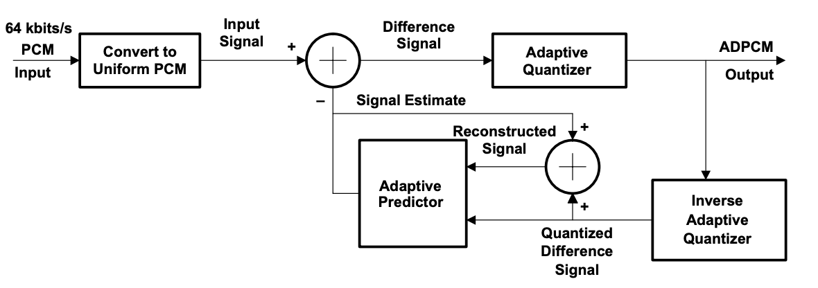
A difference signal is obtained by subtracting an approximation of the input signal from the input signal itself after the A-law or -law PCM input signal is converted to uniform PCM.
The value of the difference signal is assigned five, four, three, or two binary digits, respectively, by an adaptive 31-, 15-, 7-, or 4-level quantizer for transmission to the decoder. From the same five, four, three, or two binary digits, an inverse quantizer generates a quantized difference signal. To obtain the reconstructed version of the input signal, the signal estimate is applied to this quantized difference signal.

Fig 1: ADPCM Encoder
ADPCM Decoder
The decoder has the same structure as the encoder's feedback section, as well as a uniform PCM to A-law or -law conversion and synchronous coding adjustment. In such conditions, the synchronous coding modification avoids cumulative distortion on synchronous tandem coding (ADPCM, PCM, ADPCM, etc., digital connections). The synchronous coding adjustment is accomplished by changing the PCM output codes in such a way that quantizing distortion is avoided in the next ADPCM encoding level.

Fig 2: ADPCM Decoder
Key takeaway:
G.728 is capable of passing low-bit-rate modem signals up to 2400 bits per second. 30 million instructions per second is the complexity of the codec (MIPS). G.728 has an algorithmic coding delay of 0.625 milliseconds and is used in applications that need a short algorithmic delay.
It's an optional codec for audio or video telephony on switched wireless circuits that complies with the H.320 norm. The ITU-T G.728 recommendation is followed by the voice age G.728 implementation.
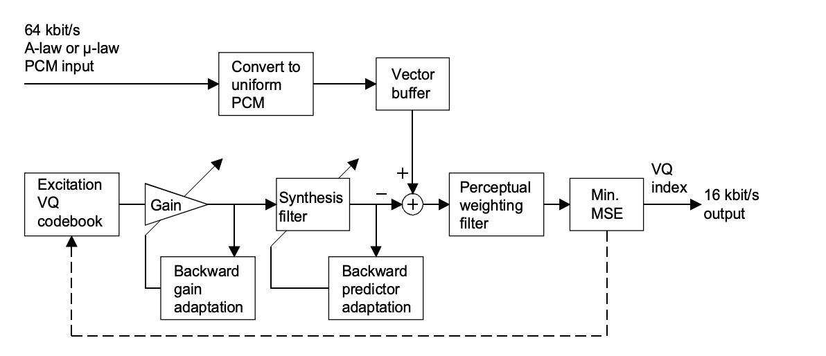
The LD-CELP algorithm consists of an encoder and a decoder. LD-CELP retains the essence of CELP techniques, which is an analysis-by-synthesis approach to codebook quests. The LD-CELP, on the other hand, achieves an algorithmic delay of 0.625 ms by using backward adaptation of predictors and gain. The index to the excitation codebook is the only thing that is sent. LPC analysis of previously quantized speech is used to update the predictor coefficients.
The gain information embedded in the previously quantized excitation is used to update the excitation gain. Just five samples are used in the excitation vector and gain adaptation blocks. Using LPC analysis of the unquantized voice, a perceptual weighting filter is modified.
LD-CELP Encoder
The input signal is partitioned into blocks of five consecutive input signal samples after conversion from A-law or -law PCM to uniform PCM. The encoder runs each of the 1024 candidate codebook vectors (stored in an excitation codebook) through a gain scaling unit and a synthesis filter for each input block.
The encoder selects the one from the 1024 candidate quantized signal vectors that minimizes a frequency-weighted mean-squared error measure with respect to the input signal vector. The decoder receives the 10-bit codebook index of the corresponding best codebook vector (or "code vector"), which generates the best candidate quantized signal vector.
The best code vector is then passed through the gain scaling unit and synthesis filter to determine the right filter memory in preparation for the next signal vector's encoding. Based on the previously quantized signal and gain-scaled excitation, the synthesis filter coefficients and gain are modified regularly in a backward adaptive manner.

Fig 3: LD-CELP encoder
LD-CELP Decoder
The decoding procedure is also carried out block by block. The decoder uses a table look-up to retrieve the corresponding code vector from the excitation codebook after obtaining each 10-bit index. To generate the current decoded signal vector, the extracted code vector is passed through a gain scaling unit and a synthesis filter.
The gain and coefficients of the synthesis filter are then modified in the same way that they were in the encoder. To improve perceptual accuracy, the decoded signal vector is then passed through an adaptive postfilter. Using the knowledge available at the decoder, the post filter coefficients are modified on a regular basis. The five samples of the postfilter signal vector are next converted to five A-law or µ-law PCM output samples.

Fig 4: LD-CELP decoder
LD-CELP (encoder principles)
The encoder is mathematically similar to the encoder shown in Figure before, but it is more computationally effective to implement.
The following is an example of a description:
● k is the sampling index for each variable to be represented, and samples are taken at 125-second intervals;
● A vector of a signal is a set of five consecutive samples in that signal. For eg, a speech vector is made up of five consecutive speech samples, an excitation vector is made up of five excitation samples, and so on.
● The vector index is denoted by n, which is distinct from the sample index, which is denoted by k.
● One adaptation cycle is made up of four vectors in a row. Adaptation cycles are often referred to as frames in a later segment. The words are often used interchangeably.
The only information directly transmitted from the encoder to the decoder is the excitation vector quantization (VQ) codebook index. The excitation gain, synthesis filter coefficients, and perceptual weighting filter coefficients are three other types of parameters that will be modified on a regular basis. These parameters are extracted from signals that arise before the current signal vector in a backward adaptive manner.
The excitation gain is modified once per vector, and the synthesis and perceptual weighting filter coefficients are updated every four vectors (i.e. a 20-sample, or 2.5 ms update period). Although the algorithm's processing sequence has a four-vector adaptation interval (20 samples), the basic buffer size is still only one vector (five samples). This limited buffer size allows for a one-way delay of less than 2 milliseconds.
Pros:
● G.728 is classified as a "toll standard." As a result, voice quality is significantly improved over previous speech codecs.
● Satellite, wireless, and video conferencing networks all use G.728 as a low delay speech coder.
Cons:
● There are only a few bits available for error protection.
Key takeaway:
To work with a discrete-time speech signal, the ITU-T standardized an 8 kbits/s speech codec. G.729 uses Conjugate-Structure Algebraic-Code-Excited Linear-Prediction to code speech signals used in multimedia applications at 8 kbits/s (CS-ACELP). Under most operating conditions, the quality of this 8 kbits/s algorithm is equal to that of a 32 kbits/s ADPCM. Mu-law or A-law 64 kbits/s PCM or 128 kbits/s linear PCM with a compression ratio of 16:l are typical input rates. All of these coders are based on a human vocal system model. The throat and mouth are modeled as a linear filter in that model, and voice is produced by periodic air vibrations exciting this filter.
Voice over IP (VoIP), Videophones, Digital Satellite Systems, Integrated Services Digital Network (ISDN), Land-Digital Mobile Radio, Future Public Land Mobile Telecommunication Systems (FPLMTS), Digital Circuit Multiplication Equipment (DCME), Digital Simultaneous Voice and Data (DSVD), and other devices will all use G.729 technology.
The coder G.729. receives an analog voice signal sampled 8000 times per second as an input signal. The coder works with 10-millisecond frames. The speech signal is analyzed for each frame in order to obtain the CELP model parameters (Linear Prediction (LP) filter coefficients, adaptive and fixed codebook index) that are then encoded and transmitted.
ENCODING
The block diagram of a G.729. encoder is shown in the figure. The input to the speech encoder is presumed to be a 16-bit PCM signal in the first block of the encoder, as specified in clause 2. Before the encoding process, two preprocessing functions are used :
To reduce the probability of overflows in the fixed-point implementation, the input is scaled by a factor of two. The high-pass filter protects against low-frequency components that are unwanted. The filter is a second order pole/zero with a cut-off frequency of 140 Hz. By dividing the coefficients at the numerator of this filter by 2, both scaling and high-pass filtering are combined.
The resulting filter is given by:

s(n) refers to the input signal that has been filtered through Hh1(z) and will be used in all subsequent coder operations. The 10th order linear prediction (LP) filters are used in the short-term analysis and synthesis filters.

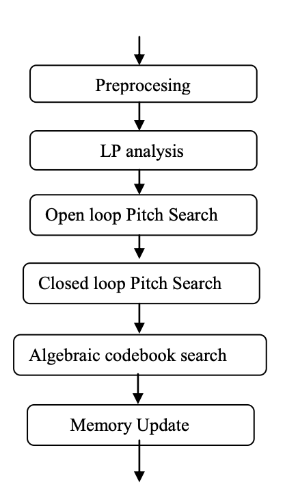
Fig 5: Block diagram of encoder
Figure depicts the G.729 encoding concept. In the pre-processing block, the input signal is high-pass filtered and scaled. All subsequent research uses the pre-processed signal as an input signal. To compute the LP filter coefficients, an LP analysis is performed once every 10 ms frame. These coefficients are quantized using predictive two-stage Vector Quantization (VQ) with 18 bits and translated to Line Spectrum Pairs (LSP).
The excitation signal is selected using an analysis-by-synthesis search technique in which a perceptually weighted distortion measure is used to minimize the error between the original and reconstructed expression. This is accomplished by applying a perceptual weighting filter to the error signal, the coefficients of which are obtained from the unquantized LP filter.
To boost output for input signals with a flat frequency response, the amount of perceptual weighting is rendered adaptive. Each sub-frame of 5 ms (40 samples) determines the excitation parameters (fixed and adaptive codebook parameters).
The quantized and un-quantized LP filter coefficients are used in the second sub-frame, while interpolated LP filter coefficients are used in the first sub-frame (both quantized and un-quantized). The perceptually weighted speech signal Sw is used to estimate an open-loop pitch delay TOP once every 10 ms frame (n).
At intermediate bit rates, either a closed or an open pitch loop is needed for good performance of the CELP algorithm. An adaptive codebook of overlapping candidate vectors can be interpreted as the closed pitch loop.
DECODING
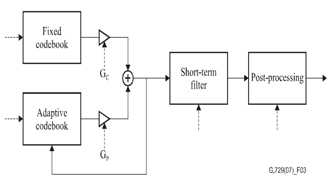
Figure depicts the decoder principle. The indices of the parameters are extracted first from the obtained bit-stream. The coder parameters for a 10 ms speech frame are obtained by decoding these indices. The LSP coefficients, two fractional pitch delays, two fixed-codebook vectors, and two sets of adaptive and fixed-codebook gains are the parameters in question. For each sub-frame, the LSP coefficients are interpolated and translated to LP filter coefficients.

Fig 6: Principle of the CS-ACELP decoder
The CS-ACELP decoder explains the encoding and post-processing processes. The decoding method uses the same procedures as the encoder to produce the LP filter coefficients from the transmitted data.
Adaptive post filtering and high pass filtering are two forms of post-processing. Personal communication systems (PCS), digital satellite systems, and other devices such as packetized speech and circuit multiplexing equipment are the key applications for this coder.
Pros:
● Speech data compression with a delay as low as 10 milliseconds. As a result, this codec cannot accurately transport music or tones such as DTMF or fax tones.
● Because of its low bandwidth requirement of about 8 kbps, it is primarily used in Voice over IP (VoIP) applications.
Cons:
● The standard of speech deteriorates slightly.
● For use, a license is required.
Key takeaway:
References:
2. 2. “Speech Coding Algorithms: Foundation and Evolution of Standardized Coders”, W.C. Chu, Wiley Inter science, 2003.
3. T-REC-G.728-199209-S!!PDF-E.pdf
4. https://www.ijsce.org/wp-content/uploads/papers/v1i5/E0144081511.pdf