Unit - 4
Impact of Jets
Force Exerted on Stationary Vanes or Plate
- A vane is defined in hydraulic machines as a flat plate or curved plate which is fixed on the rim of wheel which is known as a water wheel or a turbine.
- When a jet of water impinges normally a flat stationary vane, the force exerted by it is equal to the rate of change of momentum per second.
- Consider a flat plate as shown in Fig. Of cross-section area of the jet 'a' and 'v' is the velocity of jet.
- Mass of water striking the plate/sec
 .
. - The velocity of jet is reduced to zero after impact in its original direction as the plate is fixed.
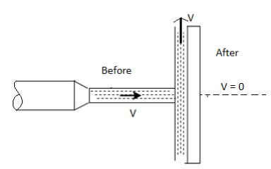
Fig: 1
∴ Force on plate = Rate of change of momentum
= (Mass of water striking the plate) x (Change in velocity in the direction normal to the plate)
F=
Force Exerted by Jet Inclined to Vane
- When a jet is impinging on a flat stationary plate at an angle as shown in Fig., the force exerted by it is calculated by
Force= Rate of change of momentum
= Mass of water x (Change in velocity in the original direction)
F =  (v-0)
(v-0)
∴F=
Where  is the inclination of jet with the vane.
Force exerted in the direction normal to the plate.
F=
Force exerted by jet in the direction of flow


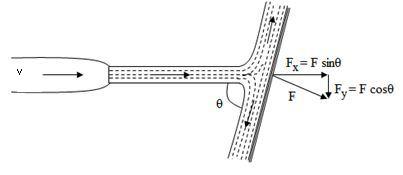
Fig: 2
Force exerted by jet in the direction normal to the flow.

Force Exerted by Jet on Moving Vertical Plate
- Consider a jet impinging normally on a plate. As a result of impact of jet, the plate moves in the direction of jet as shown in Fig.
Let
v = velocity of the jet
V1 =velocity of the plate
a = c/s area of jet
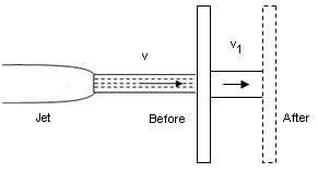
Fig: 3
Then, relative velocity = (v-v₁) as the plate moving in the same direction as that jet.
Force exerted by jet = Mass x Change in velocity
=  a
a
= Force x Displacement/sec = 
Kinetic energy of the jet, K.E. =
Efficiency=Work done/ Energy supplied
ɳ=
The efficiency becomes maximum when  becomes maximum. For maximum efficiency, differentiate
  v, w.r.t
  and equate to zero.

 =0
=0
 = 0,
= 0,
Either v- which is not practicable
v=3v1, is the condition for maximum efficiency
 ×
×
Force Exerted by Jet on Moving Inclined Plate
- Consider a plate inclined at an angle 8 with jet of water. Force exerted in direction normal to plate
F = 
Force exerted in direction of flow
 =
=
Force exerted by jet in the direction normal to the flow
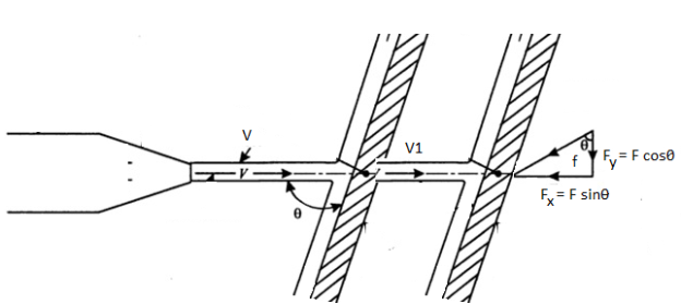
Fig: 4

Work done by jet
W. D=  Displacement /sec
W. D= .
.
Key Takeaways:
A vane is defined in hydraulic machines as a flat plate or curved plate which is fixed on the rim of wheel which is known as a water wheel or a turbine
- A hydraulic turbine is a machine which converts the pressure and kinetic energy of water called hydraulic energy into mechanical energy. These are also called as water turbines.
- The mechanical energy of turbine is further converted into electric energy by an electric generator which is directly coupled to the shaft of hydraulic turbine. The electrical power generated is known as hydro-electric power.
- Hydraulic turbines are efficient. These have low wear and tear and ease of maintenance. However, their capital cost is high with long gestation period due to the requirement of constructing the dam across the river and laying the long pipe lines.
Key Takeaways:
A hydraulic turbine is a machine which converts the pressure and kinetic energy of water called hydraulic energy into mechanical energy. These are also called as water turbines.
Hydraulic turbines are classified based on the energy. Available at the inlet of turbine, the availability of head, direction flow over the vanes in the runner and its specific speed. Following is the important classification of turbines.
Classification of Hydraulic Turbines
- According to the type of energy available at inlet to the turbine
- Impulse turbine
- Reaction turbines
2. According to direction of flow though runner
- Tangential flow turbines
- Radial flow turbines
- Axial flow turbines
- Mixed flow turbines
3. According to the head available at inlet to the turbine
4. According to the specific speed (Ns) of the turbine
5. According to discharge
6. According to speed of runner
7. According to power output, Ps
1. According to the type of energy available at inlet to the turbine:
Impulse turbine
- An impulse turbine, as the name suggests, works on the principle of impulse.
- In these turbines, the head or pressure energy of water is first converted into kinetic energy by means of a nozzle or set of nozzles kept close to the runner.
- This high velocity jet produced by nozzle is allowed to impinge on the set of buckets fixed on the outer periphery of the wheel or runner. The direction of jet is changed by buckets. The change of momentum of water causes the wheel to rotate, thus produces mechanical energy.
- It should be noted that the pressure of water is atmospheric and remains constant while passing over the runner.
- Examples of important impulse turbines are Pelton wheel, Girard turbine, Turgo turbine etc.
Reaction turbines
- In these turbines, a part of pressure energy is first converted into kinetic energy before supplied to runner.
- Turbine to run in closed passages which are completely filled with supplied to runner. Therefore, the water enters the runner having partly the pressure energy and partly the kinetic energy and both these energies are reduced simultaneously while passing over the runner and produce mechanical energy. Hence, these turbines work on the principle of impulse-reaction.
- The runner of these turbines being under pressure above atmospheric, it requires the blades of turbine to run is closed passages which are completely filled with water in all conditions
- Examples of reaction turbine are Francis, Kaplan and Propeller turbines.
2. According to direction of flow though runner
Tangential flow turbines:
- It is the turbine in which water flows tangent to the runner.
Radial flow turbines:
- It is the turbine in which the water flows in the radial direction through the runner.
Axial flow turbines:
- It is the turbine in which the water flows through the ninn along the direction parallel to the axis of rotation of runner.
Mixed flow turbines:
- It is the turbine in which water flows in the runner i radial direction but leaves in axial direction.
3. According to the head available at inlet to the turbine
- Low head turbines (2 m to 15 m)
- Medium head turbines (16 m to 70 m)
- High head turbines (71 m and above)
4. According to the specific speed (Ns) of the turbine
- Low specific speed.
- Medium specific speed.
- High specific speed.
5. According to discharge
- Turbines can be classified based on low discharge (Pelton turbine), medium discharge (Francis turbine) and high discharge (Kaplan turbine).
6.According to speed of runner
- Turbines are generally not specified based on speeds because turbines are directly coupled to generator. The generator speed is given by,

Where, f = frequency of generation in hertz
p = No of poles of the generator
- For above reason, the turbines are classified based on their specific speed and not on their actual speeds which is equal tc generator speed irrespective of power output.
7.According to power output, Ps

Where,  = 1000 g/m³ and g = 9.81 m/s²
- Therefore, power output depends on discharge (Q) in m'/s and head (H) in meters.
- Maximum power developed by one unit of turbines are as follows:
Impulse turbine = 250 MW
Francis turbine = 710 MW
Kaplan turbine = 110 MW
- Obviously for large power generation the Francis turbine is the first choice depending upon the availability head and discharge.
Key Takeaways:
Classification of Hydraulic Turbines
- According to the type of energy available at inlet to the turbine
- Impulse turbine
- Reaction turbines
2. According to direction of flow though runner
- Tangential flow turbines
- Radial flow turbines
- Axial flow turbines
- Mixed flow turbines
3. According to the head available at inlet to the turbine
4. According to the specific speed (Ns) of the turbine
5. According to discharge
6. According to speed of runner
7. According to power output, Ps
Impulse turbine:
- An impulse turbine, as the name suggests, works on the principle of impulse.
- In these turbines, the head or pressure energy of water is first converted into kinetic energy by means of a nozzle or set of nozzles kept close to the runner.
- This high velocity jet produced by nozzle is allowed to impinge on the set of buckets fixed on the outer periphery of the wheel or runner. The direction of jet is changed by buckets. The change of momentum of water causes the wheel to rotate, thus produces mechanical energy.
- It should be noted that the pressure of water is atmospheric and remains constant while passing over the runner.
- Examples of important impulse turbines are Pelton wheel, Girard turbine, Turgo turbine etc.
Reaction turbines:
- In these turbines, a part of pressure energy is first converted into kinetic energy before supplied to runner.
- Turbine to run in closed passages which are completely filled with supplied to runner. Therefore, the water enters the runner having partly the pressure energy and partly the kinetic energy and both these energies are reduced simultaneously while passing over the runner and produce mechanical energy. Hence, these turbines work on the principle of impulse-reaction.
- The runner of these turbines being under pressure above atmospheric, it requires the blades of turbine to run is closed passages which are completely filled with water in all conditions.
- Examples of reaction turbine are Francis, Kaplan and Propeller turbines.
Key Takeaways:
An impulse turbine, as the name suggests, works on the principle of impulse. In these turbines, the head or pressure energy of water is first converted into kinetic energy by means of a nozzle or set of nozzles kept close to the runner.
Reaction turbines: In these turbines, a part of pressure energy is first converted into kinetic energy before supplied to runner.
Tangential flow turbines:
- It is the turbine in which water flows tangent to the runner.
Radial flow turbines:
- It is the turbine in which the water flows in the radial direction through the runner.
Axial flow turbines:
- It is the turbine in which the water flows through the ninn along the direction parallel to the axis of rotation of turbine.
- Pelton wheel is a tangential flow impulse turbine. It was first developed by an American Engineer Lester Allen Pelton in the year 1880.
- In Pelton turbines the water strikes the buckets along the tangent of the runner or wheel.
- It is used for high heads more than 100 m of water. These turbines have been built upto head of 1600 m.
Construction and working of Pelton Wheel:
- An arrangement of Pelton turbine is shown in Fig.
- The water from reservoir flows through the penstock to the nozzle which converts the pressure energy (high head of water) into kinetic energy.
- The resultant high velocity jet from nozzle strikes the buckets or vanes fitted at outer periphery of runner.
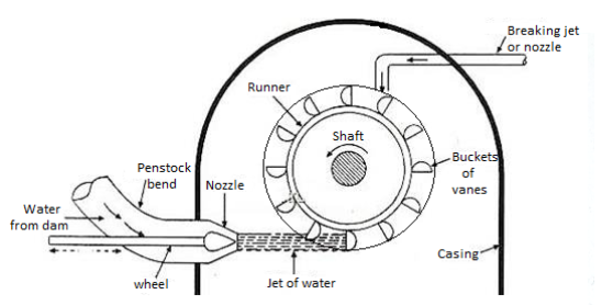
Fig 5: Pelton turbine
The main components of a Pelton wheel are:
- Nozzle and spear assembly
- Runner and buckets
- Casing
- Braking jet
- Deflector
1. Nozzle and spear assembly:
- The needle spear is provided in the nozzle to regulate the water flow through the nozzle. Also, it provides the smooth flow of water with negligible loss of energy.
- A spear is a conical needle which can be moved in axial direction by operating the wheel either manually or automatically.
- When the spear is moved in forward direction into the nozzle, it reduced the nozzle exit area, hence, the quantity of water flow striking the buckets is reduced. If the spear is moved backwards, it increases the flow rate of water.
- The nozzle converts the potential energy of water into kinetic energy before jet strikes the buckets. Pressure at exit of nozzle is reduced to atmospheric pressure.
2. Runner and buckets:
- The turbine rotor called runner is a circular disc fixed with buckets. It is provided with cylindrical boss and keyed to the supporting shaft in small thrust bearings.
- The runner carries cup shaped buckets more than 15 in number which are mounted at equidistance around its periphery. The buckets are either cast integrally with the circular disc or these are bolted individually to the runner, it helps in easy replacement of buckets when worn out.
- Buckets are made of cast iron cast steel, special steels or stainless steel with inner surface polished to reduce friction losses of water jet. Type of metal used for bucket depends on the head at turbine inlet.
- The shape of the buckets is of double hemispherical cup or bowl. Each bowl of the bucket is separated by a wall called splitter or a ridge.
- The shape and dimensions of a bucket are shown in Fig.
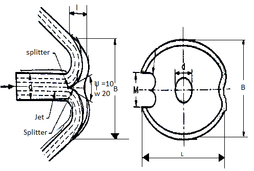
Fig 6: Bucket dimensions
- The commonly adopted dimensions of bucket are
d =Diameter of jet
L = Length of height of bowl is the rim= 2d to 3d
B =Width of bucket between the rims of bowl= 3d to 4d
T = Depth of bowl = 0.27 B to 0.32 B
M= Notch width= 1.1 d to 1.2 d
Splitter angle,
 = 10° to 20⁰
- The water strikes the bucket at the splitter which splits the water into two equal streams of the hemispherical bowl.
- The maximum force will be obtained when the jet is deflected through 180° into exact hemispherical bowl. However, in practice the jet is deflected through 160° to 170
 [splitter angle = 10° to 20°] It avoids striking the exit jet with the back of une succeeding becket, thus exerting a retarding force on it. It would reduce the power output and the overall efficiency of turbine.
 - This also avoids the splashing of water with a splitter. Pelton wheel is provided with two hemispherical cups since the splitter splits the jet into two equal streams, the axial component of each stream velocity is equal and opposite due to which the axial thrust on the shaft is negligible. Therefore, Pelton wheel needs very small thrust bearings.
- An undercut is provided and surface of spoons is raised so that water can be deflected back through the angle of 160° to 170° with the vertical without disturbing the incoming bucket.
3. Casing
- A casing does not have any hydraulic function to perform therefore it is not actually needed in case of impulse turbines because the runner runs under atmospheric pressure.
- However, a casing is provided to prevent the splashing of water and lead the water to tail race, and to safeguard the persons against accidents. It is made of cast iron in two halves.
4. Braking Jet
- Whenever the turbine is brought to rest, the nozzle is completely closed by pushing forward the spear. However, the runner continues to rotate due to its inertia for a considerable period of time till it comes to rest.
- In order to bring the runner to stop in a shortest time, a small nozzle is provided which issues the water jet and falls on the back of bucks. It acts as a hydraulic brake for reducing the speed of runner.
5. Deflector
- A deflector is provided which is hinged to the casing to deflect the jet of water away from striking the buckets in case the load on turbine suddenly reduces.
- It prevents the runner of turbine attaining unsafe speeds called runaway speed.
- A governing mechanism is also provided to control the speed of turbine according to variation in load which shall be discussed in later chapters in detail.
Design Aspects and Important Points to Remember for Pelton Wheel:
1. Velocity of Jet V,

Cv = 0.97 to 0.98;
H=net head on turbine
2. Velocity of wheel, u

3. Speed ratio, Ku
- Also, we define peripheral coefficient or speed ratio, Ku as the ratio of runner speed to the velocity of jet. Therefore,

- The value of Ku varies from 0.43 to 0.47.
4. Jet ratio, m
- The ratio of mean pitch diameter of wheel, D to the jet diameter, d is called jet ratio, m.
- Therefore,
- Jet ratio, m = Mean pitch diameter of wheel, D/Jet diameter, d
- The value of jet ratio m varies between 11 to 15. However, m= 12 is adopted in most cases.
5. Number of jets,
- It is determined by dividing the total flow rate of water through the turbine to the rate of flow of water through a single nozzle.
- Usually, a single nozzle is used in Pelton wheel. However, up to 4 nozzles can be used to produce more power from the same wheel. These nozzles are equi-spaced around the wheel. Number of jets are decided based on the total discharge and jet ratio.
6. Angle of deflection of jet, (180- )
)
- The angle of deflection of jet through the bucket varies between 160° to 170°.
- However, the angle of deflection of jet can be taken as 165° if no angle of deflection is specified.
Key Takeaways:
Pelton wheel is a tangential flow impulse turbine. It was first developed by an American Engineer Lester Allen Pelton in the year 1880.In Pelton turbines the water strikes the buckets along the tangent of the runner or wheel.
- Dimensions of the bucket are determined from emperical relations as follows:
Let, d= diameter of the jet. Then,
Width of bucket, B=4d
Depth of bucket, T=0.3d
Length or height of bucket, L = 2.5 d
Notch width, mw = 1.15 d
- The number of buckets on the periphery of runner is decided based on the following considerations:
- The number of buckets should be as few as possible to have the minimum friction losses.
- Jet of water issued by nozzle is fully utilized so that no water goes as waste i.e., no water leaves without striking at least one bucket of the runner.
- Theoretical number of buckets required can be calculated as follows:
- Fig. Shows a jet of water striking the buckets of a Pelton wheel with 'O' as centre.
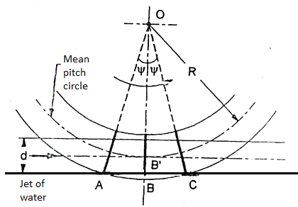
Fig 7: Number of Buckets
- The centre line of jet touches the pitch circle of bucket B and it receives the full jet. A and C are adjacent buckets.
- The incoming bucket A has just started receiving the full jet and the position C of the bucket shows when it just goes out receiving the full jet. Let:
R= mean pitch circle radius of bucket
d =diameter of jet
n = theoretical number of buckets
 = angle subtended by adjacent buckets at the centre of runner 'O'.
h =depth of bucket which is usually taken as 1.2 d.
- Consider
 OAB' in which,
OA=R+
OB' = R +0.5 d
∴ …(1)
…(1)
- Jet ratio, m was defined by the Equation as,

Therefore, Equation can be rewritten as:

∴ ….(2)
….(2)
- Then the number of buckets may be found by the relation,
Number of buckets Z= 360°/ …(3)
…(3)
- Theoretical number of buckets calculated by Equation (3) are almost twice the number of buckets used in practice since the theoretical number of buckets cannot be used due to non-availability of space on runner.
- This has led to estimation of number of buckets by using certain empirical relations as follows:
- Dr. H. F. Taygun suggested the following empirical relation for determination of number of buckets,
- Buckets,
Z=15+0.5 m = 15 +0.5 …(4)
…(4)
- Usually the value of jet ratio, m is adopted as 12.
Hydraulic efficiency of jet, nh:
- It is defined as the ratio of power delivered by runner to the power supplied at inlet. The power supplied at inlet is also called water power which is equal to kinetic energy of jet supplied to runner.
Kinetic energy supplied to jet per second = 
Hydraulic efficiency, nh =
- Sometimes, the hydraulic efficiency is also called as bucket efficiency.
Mechanical efficiency, ɳm:
- It is defined as the ratio of power available at turbine shaft to the power developed by runner. Difference of these two powers is due to mechanical losses caused by friction between mating parts (e.g., in shaft and runner, bearings etc).
- Mechanical efficiency, ɳm =

Volumetric efficiency, ɳv:
- It is defined as the ratio of the volume of the water actually striking the buckets to the volume of water issued by the jet. Hence,
Volumetric efficiency, ɳv=
- Volumetric efficiency is less than 100% since some quantity of water misses the bucket and directly it passes to tail race without doing any useful work.
- Volumetric efficiency for Pelton wheel ranges from 97% to 99%.
Overall efficiency, ɳo:
- It is defined as the ratio of power available at turbine shaft to the power supplied by water jet. Accordingly,
Overall efficiency, ɳo=
∴
- We have already discussed that in case of impulse turbines the total head available is first converted into velocity head in nozzles before the water enters the runner.
- Whereas, in case of reaction turbines only a part of total available head is converted into velocity head while passing over the fixed guide vanes before it enters the runner.
- Therefore, in reaction turbine the water enters the runner under pressure having some velocity head: While the water passes over the runner, its pressure is gradually converted into velocity head until its pressure is reduced to atmospheric pressure along with the change in kinetic energy based on its absolute velocity.
- The reaction due to pressure difference and the impulse action is responsible for rotation of runner and producing the mechanical work.
- Since the water flows under pressure over the runner, above atmospheric it is necessary that the runner must run full of water.
- The water from runner is discharged into tail race through a closed tube of gradually increasing cross-sectional area called a draft tube.
- Also, the cross-sectional of flow through the passages of runner must gradually increase to accommodate the change in static pressure of water.
- The reaction turbines are suitable for low and medium heads ranging from 30 m to 250 m of head some of the important reaction turbines are Fourneyron, Francis, Kaplan and propeller turbines.
Key Takeaways:
We have already discussed that in case of impulse turbines the total head available is first converted into velocity head in nozzles before the water enters the runner. Whereas, in case of reaction turbines only a part of total available head is converted into velocity head while passing over the fixed guide vanes before it enters the runner.
Francis Reaction Turbines:
A Francis reaction turbine is shown in Fig.
The main components of a reaction turbine are:
- Scroll casing
- Guide mechanism
- Runner and shaft
- Draft tube
Scroll casing:
- Water from penstock flows into the outer scroll casing of turbine which is made in spiral shape. The casing surrounds the guide vanes, the runner, the shaft etc.
- The casing and runner always run fell of water.
- The cross section of the casing is made of decreasing area so that the water is evenly distributed around the circumference of runner almost at constant velocity and pressure.
- The material used for casing of a reaction turbine depends on the head it works. The casing is usually made of concrete for less than 30 m head, of welded rolled steel plates upto 100 m head and of cast steel for more than 100 m head.
- In large units, stay vanes are provided inside the casing to support it. Stay vanes also help in guiding the water from casing to guiding vanes so that water is equally distributed around the periphery without formation of any eddies.
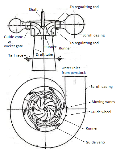
Fig 8: Francis reaction turbine
Guide Mechanism:
- It consists of a stationary ring in the form of a wheel called guide wheel. It surrounds the outer periphery of runner and is fixed to inner surface of casing.
- In between the outer and inner ring of guide wheel, it carries a series of guide vanes or wicket gates of aerofoil section. These vanes form the number of passages between the casing and runner blades. Though these vanes are fixed in position but they can be rotated about their respective pivots.
- The guide vanes have the following functions to perform:
- To direct the water from casing to moving vanes of runner at inlet without shock. In order to achieve smooth and shockless entry to runner, the relative velocity of water must be kept tangent to inlet tip of runner.
- To regulate the discharge according to load on the turbine.
- It is achieved by swinging the guide vanes about their own pivots by opening or closing the guide vane passages.
- Swinging action of guide vanes is obtained by the regulating rod connected to regulating shaft operated by Servo-motor governing mechanism.
Runner and shaft
- The runner is keyed to the main shaft of the turbine. Shaft may be horizontal or vertical, accordingly the turbines are called horizontal turbines and vertical turbines.
- The shaft is made of steel and it is supported in thrust bearings.
- The runner consists of suitable designed blades of aerofoil section so that the water enters and leaves the blades without shock. The number of blades usually vary between 16 to 24.
- The surfaces of moving vanes are made very smooth to reduce friction losses.
- The runners are made of cast iron for low head turbines and it is made of stainless steel for high head turbines.
- A runner for a mixed flow turbine is shown in Fig.
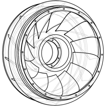
Fig 9: Runner of mixed flow reaction turbine
Draft Tube
- Water passing over the runner blades is discharged to tail race through a gradually increasing area, called draft tube.
- The small end of draft tube is fixed to outer opening of the casing and its bigger end is deeply submerged into tail race by at least 1 m depth from tail race level.
- It is evident from discussion that the entire passages of a reaction turbine from head race to tail race are totally enclosed and it does not communicate with the atmosphere. It is so necessary since reaction turbines run under pressure.
The functions of a draft tube are-
- It large converts the kinetic energy of water at exit of runner into useful pressure energy and the water discharges into tail race at very low velocity. Therefore, increases the pressure head.
- It increases the head on the turbine by an amount equal to the height of runner outlet above the tail race.
- It improves the efficiency the efficiency of the turbine.
Kaplan Turbines:
- The propeller and Kaplan are propeller shaped axial flow reaction turbines in which the water flows parallel to the axis of the shafts. These turbines were developed to meet the requirement of using available large quantity of water at low heads (upto 80 m).
- In the year 1910, Prof. V. Kaplan developed a propeller turbine having fixed runner blades of aerofoil section fixed to the hub of the shaft.
- Subsequently, Kaplan modified the design of propeller turbine in the present form of Kaplan turbine which has adjustable blades against the non-adjustable blades.
- The runner of a Kaplan turbine is shown in Fig.
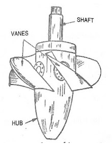
Fig 10: Runner of a Kaplan turbine
- It has a vertical hollow shaft which is enlarged at the bottom in the shape of propeller called hub or boss.
- The vanes are fixed on the hub which acts as the runner of Kaplan turbine.
- The runner vanes are 3 to 6 in numbers (upto 8) made of stainless steel. These vanes are adjustable and can be rotated about pivots fixed to the hub of runner.
- These vanes are adjusted automatically by governor mechanism according to the load on the turbine.
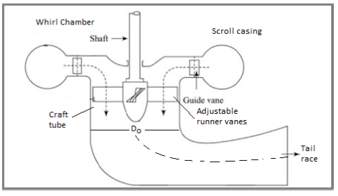
Fig 11: Construction features of a Kaplan turbine
- Due to proper adjustment of runner vanes during the running of turbine, Kaplan turbine gives high efficiency over wide range of load conditions.
- Other constructional details of a Kaplan turbine shown in Fig. Are similar to Francis turbine.
- Kaplan turbine has the scroll casing, guide mechanism and draft tube similar to Francis turbine except that it has different type of runner. Water from penstock enters the scroll casing into guide vanes. The water from guide vanes turns through 90° and enters the runner vanes axially.
- In case of Francis turbine, the water enters the runner radially while in Kaplan turbine the water strikes the runner axially. Kaplan turbine has very few moving vanes compared to Francis turbine. It reduces the friction resistance due to reduced surface contact of water with vanes.
- Kaplan turbines with sloping guide vanes taken the place of Francis turbine for certain medium installations.
Key Takeaways:
The main components of a reaction turbine are:
- Scroll casing
- Guide mechanism
- Runner and shaft
- Draft tube
Calculation of work, Power and efficiencies of Inward Radial reaction turbine:
- In case of inward radial flow reaction turbines, the water enters the runner at outer periphery of wheel and flows towards the centre of runner.
- The velocity diagram of an inward flow reaction turbine is shown in Fig.
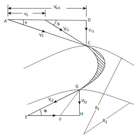
Fig 12: Velocity diagram of an inward flow reaction turbine
- Let, D1 and D₂ the outer and inner diameters of the runner rotating at N rpm. Then,
 and
and 

Work done:
- Work done by the water on runner per second called runner power, P from Euler's momentum equation can be written as:
- Work done/s, W =
 …(1)
…(1)
Where, Q = discharge through the runner in m³/s
- Work done per second per unit weight of water per second,
 …(2)
…(2)
- Equation (1), positive sign is taken when
 is less than 90° and negative sign is taken when
  is more than 90° Maximum work occurs when
  = 90°and the absolute velocity at discharge is radial i.e., V2 is minimum and Vw2 =0 Therefore, the
Equation for work reduces to:
 …(3)
…(3)
Under this condition: H- …(4)
…(4)
Hydraulic efficiency, ɳh
- If H is the net head available on turbine, then Power input or water power,

- Hydraulic efficiency, ɳh =
 =
=
Mechanical efficiency ɳm
ɳm=
Overall efficiency, ɳo
- ɳo=
 ɳh× ɳm
 - Hydraulic efficiency of a radial flow inward reaction turbine ranges from 80% to 90%.
Outward Radial Flow Reaction Turbines:
- Fig. Shows the sketch of an outward radial flow reaction turbine and Fig. shows the inlet and exit velocity diagrams for such a turbine.
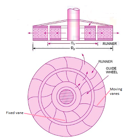
Fig 13: Outward radial flow reaction turbine
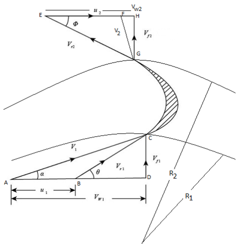
Fig 14: Velocity diagram for outward radial flow reaction turbine
- In this turbine the water, from casing enters on the guide vanes which directs the water to enter at the inlet tip of runner blades without shock.
- A part of pressure energy is converted into kinetic energy in guide vanes. The water flows over moving vanes of the runner and discharges in radial direction at outer periphery of the runner.
- In this turbine the inlet diameter D, is less than the outer diameter of runner, therefore, blade velocity u₁<u₂
- An outward radial flow reaction turbine suffers from the following disadvantages:
- There is a formation of eddies due to increasing area of flow from inlet to outlet. It causes the loss of hydraulic energy.
- Since u₂>u₁. The pressure head increases due to centrifugal action of water (Refer Equation 9.17.13). It increases the relative velocity of water at outlet and consequently tends to increase the quantity of water passing through the wheel. It decreases the power developed by the turbine.
- If there is slight reduction in load, the speed of the turbine tends to increase. It increases the centrifugal force which tends to increase the discharge rate thus the wheel tends to race. For above reasons, the outward flow reaction turbines have become obsolete. Calculation of work and efficiency is same as discussed in inward radial flow reaction turbines.
- Water turbines are designed to work under given head discharge and output at certain speed. However, the turbine may be needed to work under such operating condition which are different than designed values.
- Therefore, the performance testing of turbines becomes very essential to evaluate its characteristics.
- Also, it is essential to know the variation of its performance on all dependent parameters.
- Since the manufacturing of actual machine is highly costly and to the predict the performance of its actual machine, the performance tests are carried out on its prototypes and models.
- The important parameters on which the performance of turbine depends are head (H), discharge rate (Q), power (P) and efficiency (n). Various characteristic curves are discussed below.
Operating Characteristics (Constant Speed Characteristics)
- Operating characteristics of the turbine are obtained by testing of turbines under constant speed. Since the head cannot be changed under actual working conditions, therefore, the tests on turbine are conducted under a constant, head.
- In order to maintain constant speed, the gate openings are adjusted when the load on turbine changes, which is achieved by governing mechanism. The corresponding power input and output are measured and the efficiency is calculated.
- From the data obtained, following curves are plotted.
- Load Vs efficiency.
- Discharge Vs power.
- Discharge Vs efficiency.
1. Load Vs efficiency curves
- Fig. Shows the load Vs efficiency curve for various turbines. Load is represented as the percentage of full load for which a turbine is designed.
- In case of Kaplan and Pelton turbines the maximum efficiency is obtained at comparatively low loads compared to Francis and propeller turbines and it remains almost constant with further increase in load.
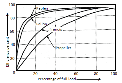
Fig 15: Efficiency Vs load curves for various turbine at constant speed and head
- Thus, these turbines can be operated at high efficiency for wide range of load conditions. Whereas, the Francis and propeller only give high efficiency at 70% or higher loads of full loads.
2. Discharge (Q) Vs power (P) and Discharge Vs Efficiency curves
- Power Vs discharge and efficiency Vs discharge curves are shown in Fig. At constant head and speed of turbine.
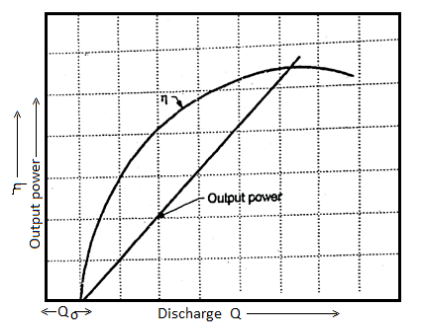
Fig 16:  and output power Vs discharge curves
- It could be seen that the efficiency of turbine increases with the increase in discharge parabolically.
- The power output varies linearly with discharge. It could be noted that power output is zero for certain value of discharge, Qo
- It is due to the fact that initially the power developed by the turbine is lost in overcoming the friction losses and the inertia load of rotating parts of a turbine.
Key Takeaways:
- Load Vs efficiency.
- Discharge Vs power.
- Discharge Vs efficiency
Draft tube:
- The functions of a draft tube are-
- It large converts the kinetic energy of water at exit of runner into useful pressure energy and the water discharges into tail race at very low velocity. Therefore, increases the pressure head.
- It increases the head on the turbine by an amount equal to the height of runner outlet above the tail race.
- It improves the efficiency the efficiency of the turbine.
Casting Cavitation:
- Only reaction turbines are subjected to cavitation. The cavitation may occur at inlet of draft tube where the pressure is considerably reduced which may be below the vapour pressure of the liquid flowing through the turbine.
- The phenomenon of cavitation is defined as the formation of vapour filled bubbles of a flowing fluids in a region where the pressure of liquid falls below its vapour pressure.
- Phenomenon of cavitation can be explained as follows:
- The vapour pressure of a liquid is the function of temperature and its height from mean sea level. In case the pressure of liquid during flow is reduced below its evaporation pressure at a given temperature, the liquid will boil and small vapour bubbles are formed. These bubbles are carried along by the fluid during flow to high pressure region where the vapours condense and the bubbles suddenly collapse. It results into formation of cavity. The surrounding liquid then rushes from all direction to fill the space thus created.
- These streams of liquid a coming from all directions collide at the centre of cavity and a very high pressure in the range of 100 to 1000 times the atmospheric pressure is generated. It generates lot of noise and vibrations and shock waves are formed.
- Sudden pressures generated by fluid produces hammering effect and damage to the metallic surface with which it is in contact. It causes the pitting of metallic parts called erosion.
Effects of Cavitation:
- The effects of cavitation are:
- Flow pattern of fluid is modified with reduced flow rate.
- Pitting and erosion of metal parts.
- Collapse of cavities cause noise and vibrations of various parts.
- Power and efficiency of turbine decreases due to cavitation.
- Structural failure may take place due fatigue because of high rate of bubble collapse
Methods of Preventing Cavitation
- The occurrence and the resulting damage can be prevented by:
- Installation of turbine near tail race.
- The pressure of fluid at any point should not fall below its vapour pressure. At any point the absolute pressure should not fall below 2.5 m of water.
- The runner blades are either made or coated by special cavitation resistant metals like stainless steel, nickel steel, aluminium, bronze.
- Prestressing the parts likely to be subjected to cavitation.
Recent Development to Prevent Cavitation:
- Various researches have suggested the following methods to prevent cavitation:
- Air injection at high pressure into flow behind the runner where vertices are formed.
- Cathodic protection of runner blades by electric current of certain voltage to evolve hydrogen from water. Hydrogen produces cushing effect on to runner blades.
- By providing a in the blades, it will cause suction which will prevent separation.
- By providing small slots in draft tube, the air is sucked from conical draft the walls of draft tube.
Key Takeaways:
Only reaction turbines are subjected to cavitation. The cavitation may occur at inlet of draft tube where the pressure is considerably reduced which may be below the vapour pressure of the liquid flowing through the turbine
Numericals:
Q. A Pelton wheel having wheel diameter of 1.2 m rotates at 600 rpm. Water is supplied at the rate of 0.6 m³/s under a head of 450 m. If the buckets deflect the jet through an angle 160°, find the power developed and hydraulic efficiency of the turbine. Assume coefficient of velocity as 0.97 and neglect the frictional losses in the bucket.
Soln.: Refer fig.
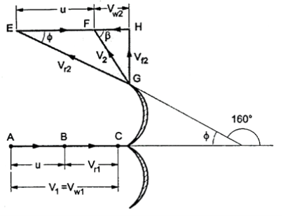
Fig: 17
Given: D = 1.2 m, N = 600 rpm, Q = 0.6 m³/s, H = 450 m,  = 180 - 160 = 20°, Kv or Cv = 0.97,
 (: Friction is neglected)
1. Power developed, P
m =  .Q= 1000 x 0.6 = 600 kg/s
 = 0.97
 = 91.14 m/s

From inlet velocity  ABC we get;


From exit velocity  EGH we get,

 =
=
2. Hydraulic efficiency, nh
ɳh =
nh = 0.9409 or 94.09%
Q. A Pelton wheel has a mean bucket speed of 12 m/s and is supplied with water at the rate of 0.7 m³/s under a head of 30 m. If the buckets deflect the jet through an angle of 160°, find the power and the efficiency of the turbine. Take Cv = 0.98.
Soln.: u =12 m/s, Q = 0.7 m³/s,
 =180-160=20°, Cv=0.98
Refer Fig.
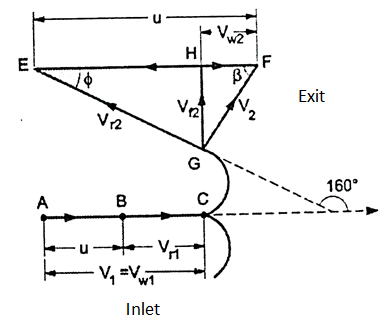
Fig: 18
Power developed, P and Hydraulic efficiency ɳh
Velocity of jet,
 = 0.98
 = 23.78 m/s


From outlet velocity  EGF,
EGF,
EH = 
∴

P =  KW =
KW = =191.94 KW

Q. A Pelton wheel with single jet rotates at 600 rpm. The pitch circle diameter of the wheel is 1.2 m and the buckets deflect the jet through an angle of 165°. The net head on the wheel is 400 m and the discharge through nozzle is 0.4 m/s. Determine the power available at the nozzle, and hydraulic efficiency of the turbine. Take coefficient of velocity as 0.97
Soln.: Refer Fig.
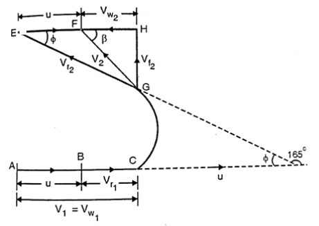
Fig: 19
Given: N= 600 rpm, D = 1.2 m, Q=0.4 m3/s; Cv=0.97;  = 180-165 = 15°; H = 400m
(i) Power available at the nozzle, Pi
Pi =  xgxQH x 10-3 kW = 1000 x 9.81 × 0.4 × 400 × 10-³ = 1569.6 kW
(ii) Hydraulic efficiency of turbine, ɳh
Velocity of jet, V₁ =  = 0.97
 = 88.6 m/s


EH = 


Q. A reaction turbine works 450 r.p.m. Under a head of 120 m. Its diameter at inlet is 1.2 m and the flow area is 0.4 m². The angles made by absolute and relative’s velocities at inlet are 20° and 60° respectively with the tangential velocity. Determine: (i) The volume flow rate (ii) The power developed (iii) The hydraulic efficiency
Soln.: Refer Fig.
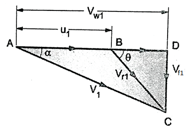
Fig: 20
N = 450 rpm, H = 120 m, D₁ = 1.2 m., A₁, = 0.4 m², =20°,
=20°,  = 60°
= 60°

1. Volume flow rate, Q
From Fig.


Also, AD=
 =
=
2.532 =
=

∴ 

2. Power developed, P

m= 
Assuming radial discharge i.e., 
P =
=  =15414.9 KW
3. Hydraulic efficiency, ɳh
ɳh =  =
=
Q. A Francis turbine with an overall efficiency of 75% is required to produce 148.25 kW power. It is working under head of 7.62 m. The peripheral velocity = 0.26  and the radial velocity of flow at inlet is 0.96
 . The wheel runs at 150 rpm and the hydraulic losses in the turbine are 22% of the available energy. Assuming radial discharge, determine: (1) The guide blade angle (2) The wheel vane angle at inlet (3) Diameter of wheel at inlet (4) Width of wheel at inlet
Soln.:
Francis turbine
 , u=
, u= ,
,  , Ps = 148.25 kW, H = 7.62 m N = 150 rpm
Hydraulic losses = 0.22 × Available energy
Radial discharge i.e.,  = 90°,
  and Vw2 = 0
Fig. (a) and (b)
 =0.26×
 =3.179 m/s
 =0.96×
 =11.738 m/s

0.75 = 
Q=2.6443 m3/s
Hydraulic losses are 0.22 times the available energy, therefore hydraulic efficiency,
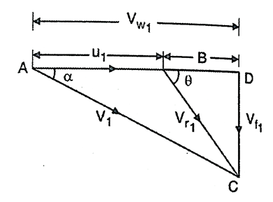
Fig: 21


0.78 =

(i) The guide blade angle, a, Consider  ACD,
ACD,

(ii) Wheel vane angle at inlet, 
BD = 

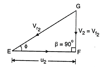
Fig: 22
(iii) Diameter of wheel at inlet, D₁

3.179=

(iv) Width of wheel at inlet, B₁
Q = 
2.6443 = 

Q. Find the force exerted by jet of water on a stationary vertical plate if the diameter of jet is 8 cm. And its velocity is 40 m/s. Assume that the jet strikes in normal direction to plate. Also find the work done.
Soln.:
Refer Fig.
Given:
d = 8 cm = 8/100 = 0.08 m,
V = 40 m/s
Assume, density of water,  = 1000 kg/m³
Cross-sectional area of jet, A =  (d2 ) =
  × (0.08) ² = 50.265 x 10⁻⁴ m²
Force exerted by jet of water normal to stationary plate is given by Equation as,
F = A V² = 1000 × (50.265 × 10 -4) × (40)²
F = 8042.4 N
Work done is zero since the plate is stationary.
Q. Jet of water of 60 mm strikes a symmetrical stationary curved vane at its centre and is deflected through an angle of 135°. Because of the friction over the surface the water leaving the vane has only 90% of its original velocity. If the force exerted by the jet on the plate is 1800 N find the volume flow rate of water.
Soln.: Refer Fig.
Diameter of jet, d = 60 mm = 0.06 m
 = 180° - 135° = 45°; V₁ = 0.9 V, Fn = 1800 N
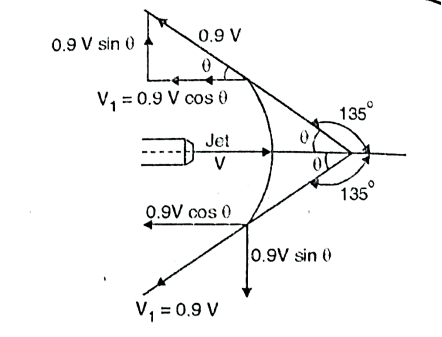
Fig: 23
Volume flow rate of water, Q
m =  AV =
AV = 
Initial velocity of jet in X-direction = V
Final velocity of jet in X-direction, V₁ = -0.9 V cos 
Vy = 0 and V₁y = 0.9 V sin 


On substituting the values,


1800= =5.0403 V^2
V =18.897 m/s
From Equation (i),
m= 2.8274 V = 2.8274 x 8.897 = 53.43 kg/s
References:
1. Fluid mechanics and machinery R Berndtsson and P.N. Chadramouli
2. Hydraulic and fluid mechanics, PM Modi and SM Seth
3. Theory and applications of fluid mechanics, K Subramanya, Tata McGraw Hill
4. Fluid mechanics with engineering applications, RL Daughterty, JB Franzini