Unit - 5
Centrifugal Pump
- The normal duty of a pump is to lift a quantity of liquid from a low level to high level and/or to transfer it from one place to another place. In order to carry out these duties by a pump, it has to provide energy:
- To lift the liquid to required height against the force of gravity.
- To overcome the fluid resistance to flow of the liquid through the pipe and the pump itself.
- Therefore, a pump is defined as a device which transfers the input mechanical energy of a motor or of an engine into pressure energy or kinetic energy or both of a fluid.
- Simply we may say that a pump is a device which converts the mechanical energy into hydraulic energy of a fluid.
Advantages of Centrifugal Pumps over Reciprocating Pumps:
- Its discharge capacity is much higher.
- It can also be used for highly viscous fluids like oils, muddy and sewage water, chemicals, paper pulp less.
- Being high speed machine, it can be directly coupled to prime mover.
- It is compact, smaller in size and has low weight for the same discharge capacity.
- It can be operated at high speed without any danger of separation and cavitation.
- Maintenance cost is comparatively very low.
- These are highly efficient.
Key Takeaways:
A pump is defined as a device which transfers the input mechanical energy of a motor or of an engine into pressure energy or kinetic energy or both of a fluid.
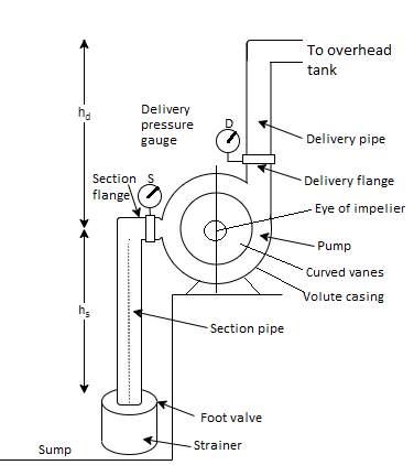
Fig 1: Components of centrifugal pump
A centrifugal pump has the following main components as shown in Fig.
- Impeller
- Casing
- Suction pipe with strainer and foot valve
- Delivery Pipe
1. Impeller
- An impeller is a wheel or rotor having a series of backward curved vanes or blades.
- The impeller is mounted on a shaft which is usually coupled to a motor. The motor provides the required input energy to rotate the impeller.
2. Casing
- The impeller is enclosed in a watertight casing with delivery pipe on one side and with an arrangement on suction side called eye of impeller as shown in Fig.
- Casing has to perform two functions. Firstly, it guides the water from entry to exit of impeller. Secondly, the casing is so designed that it helps in partly converting the kinetic energy of the liquid into pressure energy.
3. Suction pipe with strainer and foot valve
- The pipe which connects the sump to the eye of impeller is called suction pipe. The sump carries the liquid to be lifted by the pump.
- The suction pipe at its inlet is provided with a strainer and a foot valve. The function of strainer is to prevent the entry of any debris into the pump. The foot valve is a non-return valve which allows the flow of water only in upward direction.
- Therefore, this valve does not allow the liquid to drain out from suction pipe.
4. Delivery pipe
- The pipe which connects the outlet of pump upto point it delivers the liquid to required height is called delivery pipe.
- A valve is provided in the delivery pipe near the outlet of the pump called delivery valve. It is a sluice type valve. Its function is to regulate the supply of liquid from the pump to delivery pipe.
Working of Centrifugal Pump:
- Centrifugal pump works on the principle that when a certain mass of liquid is made to rotate along the impeller from the central axis of rotation, it impresses a centrifugal head. It causes the water to move radially outwards at higher velocity and causes the water to rise to a higher level. The motion of water is restricted by casing of pump, it results into pressure build up. In addition, the change in angular momentum of liquid during its flow results into increase in pressure head. The steps involved in operation of centrifugal pump are as follows:
- The delivery valve is closed.
- The priming of the pump is carried out. Priming involves the filling the liquid in suction pipe and casing upto the level of delivery valve so that no air pockets are left in the system.
If any air or gas pockets are left in this portion of pump, it may result into no delivery of liquid by the pump.
3. The pump shaft and impeller is now rotated with the help of an external source of power like a motor or any other prime mover.
The rotation of impeller inside a casing full of liquid produces a forced vortex which is responsible in imparting the centrifugal head to the liquid. It creates a vacuum at the eye of impeller and causes liquid to rise into suction pipe from the sump.
4. The speed of impeller should be sufficient to produce the centrifugal head such that it can initiate discharge from delivery pipe.
5. Now the delivery valve is opened and the liquid is lifted and discharged through the delivery pipe due to its high pressure.
Thus, the liquid is continuously sucked from the sump to impeller eye and it is delivered from the casing of pump through the delivery pipe.
6. Before stopping the pump, it is necessary to close the delivery pipe otherwise the back flow of liquid may take place from the high head reservoir.
Key Takeaways:
A centrifugal pump has the following main components as shown in Fig.
- Impeller
- Casing
- Suction pipe with strainer and foot valve
- Delivery Pipe
- A pump is a power absorbing device in which the work is done by impeller on water.
- The inlet and outlet velocity diagrams as shown in Fig. Can be drawn in similar way as drawn for an inward flow reaction turbine. Notations used are same.
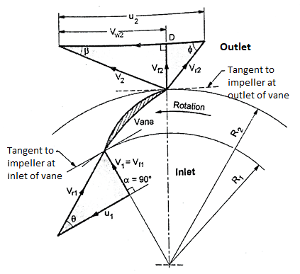
Fig 2: Velocity diagrams at inlet and outlet of impeller vanes
- In pumps, the water enters the impeller at its centre and leaves at its outer periphery. Following assumptions are made:
- Liquid enters the impeller vane radially for best efficiency i.e., α = 90 degree,
Therefore, V₁= Vf1 and velocity of whirl, Vw1 = 0.
2. Liquid enters and leaves the vane without shock.
3. The velocity distribution in passages between vanes is uniform.
Let, D₁ = Diameter of impeller at inlet = 2 x Radius, R₁
D2 =Diameter of impeller at outlet = 2x Radius, R₂
N = Speed of impeller in rpm.
- The tangential blade velocity at inlet, u1 and at outlet, u2 can be written as:

And 

V = absolute velocity;
Vr = relative velocity
Vf = velocity of flow;
Vw = velocity of whirl
- Suffix 1 and suffix 2 represent the velocities at inlet and outlet respectively.
α = angle made by absolute velocity V1 at inlet
 = inlet angle of vane
 = outlet angle of vane
 = discharge angle of absolute velocity at outlet
- Work done (W.D.) by impeller on water per N weight of liquid per second is given as,
W.D. = 
- Above Equation is known as Euler's momentum equation for centrifugal pump.
But, Vw1 = 0, since entry is radial.
W.D. = 
- In case working liquid is water and the weight of water is W, then the work done on water per second becomes,
W.D/s =w. 
Where, Weight of water/s, 
Discharge rate, Q = Area x Velocity of flow

Where, B1 and B₂ is width of impeller at inlet and outlet respectively.
Various efficiencies related to centrifugal pump are:
1. Mechanical efficiency, 
- The ratio of power available at the impeller Le. Power delivered by impeller to liquid to the power input at the shaft (motor power or shaft power) is known as mechanical efficiency.
- Therefore,

- But power available at impeller is given as,
P = 

Where, q= leakage loss
- Value of mechanical efficiency ranges between 95% to 98%.
2. Manometric efficiency, 
- It is defined as the ratio of manometric head, Hm developed by the pump to the head imparted by the impeller to liquid
- Mathematically,

3. Volumetric efficiency, 
- It is ratio of actual liquid discharged from the pump in m'/s to the theoretical liquid passing through the impeller in m3/s. Mathematically.
 =
=
Where, q represents the loss of discharge due to leakage loss.
4. Overall efficiency, 
- It is defined as the ratio of power output of the pump called water power to the shaft power.
Thus, 
Also,  =
=
Key Takeaways:
- Mechanical efficiency
- Manometric efficiency
- Volumetric efficiency
- Overall efficiency
- The centrifugal pumps with two or more number of identical impellers are called multistage centrifugal pumps.
- The impellers of these pumps may be attached on the same or on different shafts. The multistage pumps are needed either to increase the head or the discharge compared to a single stage pump, accordingly the impellers are connected in series or parallel as follows:
Multistage Centrifugal Pumps for High Heads:
- Two or more identical impellers are connected in series to generate high heads with constant discharge.
- The arrangement of multistage pump with two impellers in series is shown in Fig.
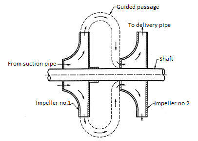
Fig 3: Impellers in series for heads
- The water from suction pipe is supplied to impeller - 1 where its head is raised. The discharge from impeller 1 is guided through the guided passages into the inlet of impeller- 2 where its pressure is further increased. If there are more number of impellers in series the similar operations are conducted and finally the last impeller in series discharges the water.
Let,
n = number of impellers
Hm = head developed by each impeller
Total head developed, H= n.Hm
- Total discharge passing through each impeller remains the same.
Therefore, Qtotal = Q
- These pumps are used where high heads are needed at relatively low discharge as in boiler practice.
Advantages of multistage pumps:
- Advantages of multistage pumps in series compared to single stage pump are:
- Friction losses are reduced due to reduced head on each impeller requiring lower speeds.
- Stresses are reduced.
- Impeller diameter is reduced.
- Axial thrust can be eliminated by suitable arrangement.
- Due to lower specific speed, higher suction lift is possible.
Multistage Centrifugal Pumps for High Discharge:
- Two or more identical impellers are connected in parallel to generate high discharge at constant heads.
- The arrangement of multistage pumps in parallel are shown in Fig.
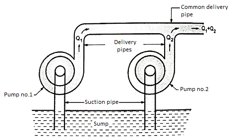
Fig 4: Pumps in parallel
- Each pump works as a separate unit and lifts the water from the sump by their respective suction pipes and their delivery pipes are connected to common delivery pipe as shown in Fig. Each pump develops the same head and discharge of pumps are added. Therefore,
Total head, Htotal = Head developed by each impeller, Hm
Total discharge, Qtotal = Number of pumps x Q
Where, Q is the discharge of each centrifugal pump.
Key Takeaways:
The centrifugal pumps with two or more number of identical impellers are called multistage centrifugal pumps.
- A centrifugal pump is designed to develop certain manometric head and discharge at constant speed since the pumps are usually driven by A.C. Motors.
- In certain cases, the pumps may be driven by an I.C. Engine at variable speed or the pump in actual practice may needed to develop a certain head or discharge. Under these actual conditions, the behaviour of the pump will be different than expected. Therefore, various tests on the pump under variable conditions are conducted in order to predict the behaviour and performance of the pump. The test results are then plotted on a graph under different flow rates, head and speed.
- The curves thus obtained are known as characteristic curves for the pump.
Types of Performance Characteristic Curves:
- The performance characteristic curves are broadly divided into following four categories:
- Main characteristic curves
- Operating characteristic curves
- Iso-efficiency or Maschel curves
- Constant head and constant discharge curves
1. Main Characteristic Curves:
- Main characteristic curves are obtained by test run at constant speed and the discharge is varied by means of delivery valve.
- At each discharge, the manometric head Hm and input power P are measured and the overall efficiency
 , is calculated.
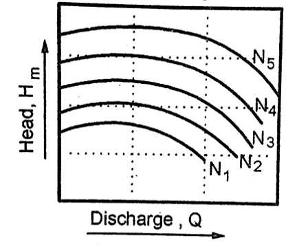
Fig 5: H vs Q
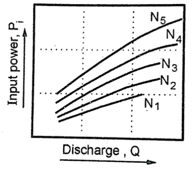
Fig 6: Pi Vs Q
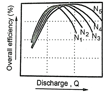
Fig 7:  Vs Q
Vs Q
- Test curves are plotted as shown in fig. For that constant speed.
2. Operating Characteristic Curves:
- The pumps are designed for maximum, efficiency at given speed called designed speed.
- Therefore, the pumps are test run at designed speed as provided by the manufacturer of the pump.
- The discharge is varied as discussed in case of main characteristic curve and the head and power input are measured. The overall efficiency of the pump is calculated.
- The performance curve thus obtained at design speed are called operating characteristic curve at shown in Fig.
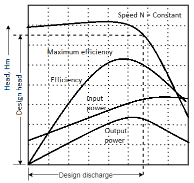
Fig 8: Operating characteristics curves of a centrifugal pump
3. Iso-efficiency or Maschel Curves:
- Iso-efficiency i.e., constant efficiency curves are useful in predicting the performance on entire operations and its best performance.
- These characteristic curves can be drawn with the help of
 and Hm Vs Q curves shown in Fig. (c) and Fig.(a) respectively. The method is as follows:
- Draw a horizontal line on
 curve. It represents the constant efficiency line.
 - The points at which the constant efficiency line cuts the constant speed lines, the discharges are noted.
- At a given discharge and speed, the Hm is noted from H Vs Q graph.
- These values of H and at constant efficiency and speed are projected on a graph of H Vs Q shown in Fig.
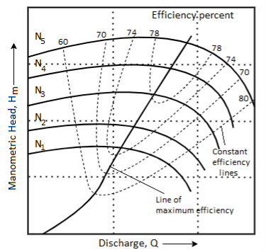
Fig 9: Iso-efficiency curves of a centrifugal pump
5. The points corresponding to same overall efficiency are then joined with a smooth curve as shown in Fig. These curves represent the iso-efficiency curves.
These iso-efficiency curves help to locate the regions where the pump would operate at maximum efficiency.
4. Constant Head and Constant Discharge Curves
- Often a centrifugal pump is draw required to operate variable speed than the designed speed. Therefore, it is necessary to the performance curves of a pump at variable speed so that these curves can be used to predict the performance.
- The procedure is as follows:
- The delivery valve opening is fixed and kept constant during the test on pump. Then it is operated at variable speed. For each speed the manometric head Hm, discharge Q and power input Pi, are measured.
- The graphs H Vs N, Pi Vs N and Q Vs N can be drawn as shown in Fig.
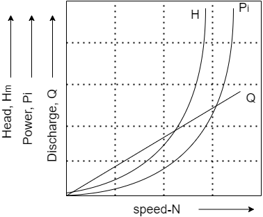
Fig 10: Head, discharge and power characteristics curves at variable speeds
Key Takeaways:
Types of Performance Characteristic Curves:
- The performance characteristic curves are broadly divided into following four categories:
- Main characteristic curves
- Operating characteristic curves
- Iso-efficiency or Maschel curves
- Constant head and constant discharge curves
- The net positive suction head (NPSH) is defined as the absolute pressure head at the inlet to the pump to force the liquid into the pump at a given temperature.
- Fig. Shows how the pressure at the eye of impeller falls below the atmospheric pressure.
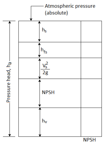
Fig 11: NPSH
- It is necessary that NPSH is positive to avoid cavitation and force the liquid into the eye of impeller.
Therefore,
NPSH = 
NPSH = 
- The value of NPSH is mainly affected by the temperature of liquid to be handled by the pump since hv and hfs are the function of temperature.
NPSH (Required)
- Required NPSH is based on the pump design and its speed and capacity. It is then tested to determine the NPSH at which the pump gives the maximum efficiency. Accordingly, the value of NPSH required is specified by the manufacturer of the pump. It represents the minimum value of NPSH to avoid cavitation at specified discharge and speed.
NPSH (Available)
- Available NPSH of the pump is estimated after installation of pump which is based on the suction pipe diameter, liquid to be handled and temperatures of operation (both the place of installation and the liquid temperature), length of suction pipe and its coefficient of friction and flow rates. While estimating this NPSH, the diameter of suction pipe must be same as per manufacturer's design specifications.
- In order to have cavitation free operation of pump the available NPSH must be greater than the required NPSH. NPSH available must be higher than NPSH required.
Key Takeaways:
The net positive suction head (NPSH) is defined as the absolute pressure head at the inlet to the pump to force the liquid into the pump at a given temperature
- Cavitation is defined as the phenomenon of formation of vapour bubbles in the region of flowing liquid where its pressure falls below the vapour pressure of liquid, then the liquid will vapourise and flow will no longer will be continuous.
- When these vapour bubbles travel into the region of higher pressure, they suddenly collapse on the metallic surfaces and the surrounding liquid rushes to fill the cavities of vapour bubbles. The severe rush of liquid causes the development of extremely high pressures.
- Prolonged cavitation causes erosion and pitting of metals, severe vibrations and noise. Fig. Shows the suction side of pump. Consider two points A and B at inlet to eye of impeller and on the sump level respectively.
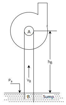
Fig 12: Cavitation in pumps
Let,
Pa = absolute atmospheric pressure;
Ps = absolute pressure at eye of impeller
hs = suction lift
Vs = velocity in suction pipe
hfs = friction losses in suction pipe
By Bernoulli's theorem,

- Therefore, the absolute pressure at inlet to eye of impeller falls below that of atmospheric pressure.
Key Takeaways:
Cavitation is defined as the phenomenon of formation of vapour bubbles in the region of flowing liquid where its pressure falls below the vapour pressure of liquid, then the liquid will vapourise and flow will no longer will be continuous.
- A reciprocating pump is a positive displacement pump in which the liquid is actually sucked and then displaced by a piston-cylinder arrangement which is driven to and fro by a crank and connecting rod mechanism. It results into lifting of liquid to a required height.
- The pumps designed with disc pistons can develop pressures upto 25 bar and the plunger pumps can built pressures very high pressure.
- The discharge rate of liquid in case of reciprocating pumps is wholly dependent on its speed and their efficiency is about 10 to 20% higher compared to centrifugal pumps. However, the capital cost and the maintenance cost of these pumps is higher than a comparable centrifugal pumps. Due to this, these pumps are not used now a days for industrial applications.
- These pumps are only suitable for low discharge and high heads. These pumps are generally employed as feed water pump in boiler operation, hydraulic jacks, pneumatic pressure systems, kerosene pumps, small hand operated pumps. Pressure washing in service stations, firefighting applications.
Classification of Reciprocating Pumps:
Reciprocating pumps are classified as:
1. According to the liquid being in contact with piston
- Single acting pump in which the liquid remains in contact only with one side of the piston.
- Double acting pump in which liquid remains in contact with both sides of the piston.
2. According to number of cylinders in a pump
- Single cylinder pump.
- Multicylinder pumps in which the pump has two or more cylinders.
Constructions of a Reciprocating Pump:
- Fig. Represents a schematic diagram of single acting reciprocating pump.
- The different components of reciprocating pumps are described here.
- Crank and connecting rod mechanism: Crank are mounted on crankshaft which is driven by either I.C. Engine or electric motor. Crank is connected to the piston by connecting rod thus converting rotary motion of crank into reciprocating motion of piston.
- Piston and cylinder: The piston reciprocate inside cylinder. The reciprocating motion of piston is obtained by connecting rod which transfer rotary motion of crank. Connecting rod is connected to piston by piston pin.
- Suction pipe: It is the pipe which is connected to the suction of the pump. Through this pipe, the liquid will be sucked from sump. It is provided with a non-return valve called suction valve.
- Delivery pipe: It is connected to discharge end. It carries liquid at high pressure at some height. It is provided with a non-return valve called delivery valve.
- Sump: It is the reservoir of liquid through which water will be pumped.
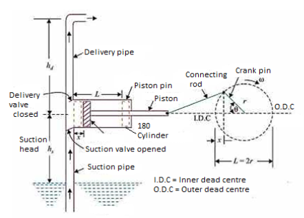
Fig 13: Reciprocating pump
Key Takeaways:
A reciprocating pump is a positive displacement pump in which the liquid is actually sucked and then displaced by a piston-cylinder arrangement which is driven to and fro by a crank and connecting rod mechanism. It results into lifting of liquid to a required height.
Working of Single Acting Reciprocating Pump:
As shown in Fig. a single acting reciprocating pump has one suction and one delivery pipe. It is usually placed above liquid level in the sump.
- Initially the crank is at inner dead centre (I.D.C.) and starts rotating in clockwise direction. As crank rotates, the piston moves towards right and vacuum is created on the left side of piston. This vacuum causes the opening of suction valve and simultaneously the liquid will be forced from sump to the left side of the piston. When crank reaches to O.D.C., the piston is on extreme right position and suction stroke is completed. The cylinder is full of liquid.
- When crank again rotates from O.D.C. To I.D.C. In clockwise direction, the liquid will be compressed and high pressure will be built in the cylinder. Due to increased pressure, delivery valve opens and liquid is forced into delivery pipe. The liquid is carried to discharge tank through delivery pipe. At the end of delivery stroke, the crank comes to I.D.C. And the piston is at the extreme left position.
Working of Double Acting Reciprocating Pump:
Fig. Represents working of double acting reciprocating pump.
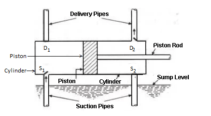
Fig 14: Double acting reciprocating pump
In a double acting reciprocating pump, both suction and delivery strokes occur simultaneously.
- When the crank rotates from I.D.C. In clockwise direction, a vacuum is created on left hand side of piston and the liquid is sucked from the sump through suction valve S₁. At the same time, the liquid on the right-hand side of the piston is compressed and high-pressure liquid causes the opening of delivery valve D, so that the liquid is passed on the discharge tank. This operation continues till the crank reaches O.D.C.
- With the further rotation of the crank, the piston now moves towards I.D.C. At this time the water will be sucked through suction valve S₂ since vacuum will be created on right hand side of piston. At the same time, the liquid on left hand side of piston will be compressed which forces delivery valve D, to open so that liquid will rise through that delivery pipe. This operation continues till the crank reaches I.D.C., when piston is at extreme left position.
Thus, the cycle is repeated again and again. Because of continuous delivery strokes, the discharge obtained through this pump gives more uniform discharge.
Consider a single cylinder, single acting reciprocating pump and let:
D = Diameter of piston or cylinder (m)
A = Cross-sectional area of piston =D² (m²)
L = Length of stroke (m)
N = Speed of pump (r.p.m.)
- Theoretical discharge, Qt in m3/s is given as
 (For a single acting)
 (For double acting)
- Volumetric efficiency or coefficient of discharge, Cd

- Work done per second or power input:

= , (single acting)
= , (double acting)
- Efficiency of pump, ɳ:

- The slip is defined as the difference of theoretical discharge and the actual discharge i.e.
Slip, S = 
And percentage slip =
Negative Slip of the Pump:
- Sometimes the actual discharge of a reciprocating pump is more than the theoretical discharge.
- It happens when the suction pipe is long and the discharge pipe is short. In case the pump runs at high speed, it causes the delivery valve to open even before the suction stroke is completed. It results into pushing some quantity of liquid into the delivery pipe before the commencement of delivery stroke. Thus, the actual discharge becomes more than the theoretical discharge and the slip as defined by Equation becomes negative.
Key Takeaways:
The slip is defined as the difference of theoretical discharge and the actual discharge.
- Indicator diagram is a graph between the pressure head in the cylinder and the distance travelled by the piston from inner dead centre during one revolution.
Numericals:
Q. A centrifugal pump is delivering 0.04 m3/s to a height of 20 m through a 150 mm diameter and 100 m long pipeline. If the inlet losses in suction pipe are equal to 0.33 m and friction factor is 0.06 for the pipeline, find the power required. Assume overall efficiency of the pump as 70%.
Soln.:
Given: Q = 0.04 m³/s, Hd = 20m, D = 150 mm = 0.15 m,
Length of pipe, l= 100 m, Suction losses, hfs= 0.33 m, f=0.06, Overall efficiency, ɳo = 0.7
Velocity of discharge through pipe,
 =2.2635 m/s
Friction head loss in delivery pipe,

Total head on pump, H = 
Power required to drive the pump, P
P=
P = 17.254 KW
Q. The impeller of a centrifugal pump is of 25 cm diameter and 5 cm width at the periphery. It has blades whose tip angles incline backwards 55° from the radius. The impeller rotates at 1200 rpm when it delivers a flow of 20 m/min. If the pump is designed to admit radially calculate
- Direction and speed of water as it leaves the impeller
- Torque exerted by the impeller on water
- Shaft power required. Assume mechanical efficiency = 95%, hydraulic efficiency = 75%.
Soln.:
Refer Fig.
Given: D₂ = 25 cm = 0.25 m,
B₂ = 5 cm = 0.05 m
 = 55°, N=1200 rpm, α = 90°
Q = 20 m³/min = 20/60 m³/s =1/3 m3/s
ɳmech = 0.95,  = 0.75,
Q = π D₂ B₂ Vf₂

 =8.49 m/s

Consider outlet velocity  EGF.
EGF.
HF = 

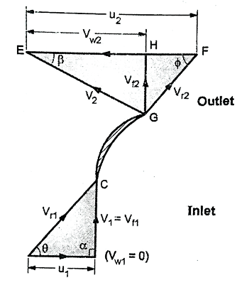
Fig: 15
(i) Direction  and speed of water V₂ as it leaves the impeller


(ii) Torque exerted by impeller on water, T
m =  .Q= 1000 x (1/3) =333.33 Kg/s

Torque, T = 
(iii) Shaft power required, Ps

=7.145×10³ W = 7.145 KW
Q. A centrifugal pump running at 1200 r.p.m. Delivers water. The diameter of the impeller at the inlet is 100 mm and at the outlet is 300 mm. The width of the impeller is 50 mm at inlet and 20 mm at the outlet. The blade angle at the outlet is 30°. If the velocity of flow at the inlet is 2.2 m/s find the velocity of flow at the outlet. Also find the head developed if the manometric efficiency is 75%.
Soln.: Refer Fig.
N = 1200 rpm;
D₂ = 300 mm = 0.3 m,
B₂= 20 mm = 0.02 m;
nmano = 0.75;
D₁ = 100 mm = 0.1 m
B₁ = 50 mm = 0.05 m
Vf1 = 2.2 m/s

1. Velocity of flow at outlet, Vf2
Discharge rate, Q

0.1

= 1.833 m/s
2. Head developed, Hm
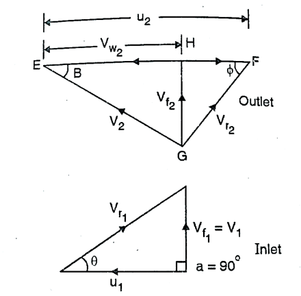
Fig: 16


References:
1. Fluid mechanics and machinery R Berndtsson and P.N. Chadramouli
2. Hydraulic and fluid mechanics, PM Modi and SM Seth
3. Theory and applications of fluid mechanics, K Subramanya, Tata McGraw Hill
4. Fluid mechanics with engineering applications, RL Daughterty, JB Franzini