Unit-1
Concept of determinate and indeterminate structures
1. Determinate structures:
If all unknown internal forces and reactive forces in a structure can be found using conditions of equilibrium alone then the structure is statically determinate. Here number of unknowns are less than or equal to condition of equilibrium, therefore there is a no need of compatibility equations.
For example
(I) A simply supported beam
(ii) A three hinge arch
(iii) A suspension bridge
Number of unknown can be found using condition of equilibrium alone.
Here number of unknown less than equal to available condition of equilibrium.
No need of other conditions for analysis of these structures.
Bending moment at a section or force in any member is independent of its material of components of structure.
Degree of indeterminacy is zero. But these structures are uneconomical.
Additional stresses are not developed due to support settelment, temperature changes and fabrication errors.
2. Indeterminate structures:
If all internal forces and reactive forces in a structure can not be found using conditions of equilibrium then the structure is statically indeterminate or redundant. So it is necessary to use basic principles of mechanics such as elasticity equilibrium and compatibility to obtain unknowns. A statically indeterminate structure said to have degree of static indeterminancy or degree of redundancy.
For example
i) Fixed beam
ii) Propped cantilever beam
iii) Two hinged arch
Number of unknown can not be found using condition of equilibrium.
Here number of unknown is greater than available condition of equilibrium.
Need of compatibility and other conditions for analysis.
Bending moment at a section is dependent on cross sectional area of components of structure.
Degree of indeterminacy is required to find out and from which we can select the method of analysis but these structures are economical.
1. Concept of Indeterminacy:
There are two type of indeterminacy that we can classify based on reaction support condition and its displacement
Static indeterminacy
Kinematic indeterminacy
2. Static Indeterminacy:
The Static Indeterminacy (SI) for beams and frames is described as,
SI = nu — ne
Where,
nu = Number of unknown assist reactions
ne = Number of equations of equilibrium
In fashionable for a -dimensional shape, there are 3 equations of equilibrium (ne = 3) and for a 3-dimensional shape there are six (ne = 6).
For a truss, static indeterminacy entails each outside and inner indeterminacy due to the inner individuals in a truss.
Static indeterminacy (SI) within side the case of a truss is described as,
SI = b + r — 2j
Where,
b = Number of individuals within side the truss
r = Number of reactions on the supports
j = Number of joints within side the truss
3. Sign Conventions
1). Static Calculations
∑F x = 0, ∑F y = 0 & ∑M = 0
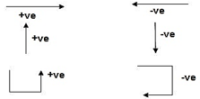
4. For Structural Actions
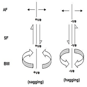
5. Degree of static indeterminacy (Dsi)
Dsi = No of Unknown Actions –No of Eqn,
Dsi = R – E
6. External Indeterminacy
When we can't discover assist reactions the use of legal guidelines at statics, it's miles referred to as externally indeterminate structure.
7. Internal Indeterminacy
When we can't discover inner member movements the use of legal guidelines of statics, its miles referred to as internally indeterminate structure.
Boundary condition
Displacement Re stained Displacement allow
Δx, Δy, ϴz Nil
Δy,ϴz, Δx
Δx, Δyϴz
Dsi for beams = R – E
Where,
R = No of assist reactions
E = No of Equilibrium equations
Note: For one inner pin, no of extra equations of equilibrium are = m – 1
m = no of individuals linked via way of means of pin.


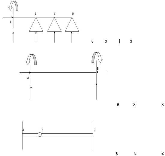
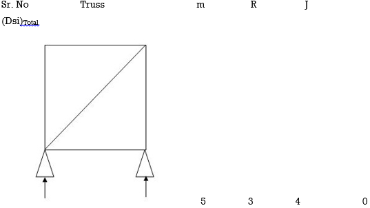
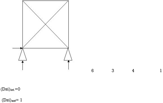
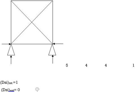
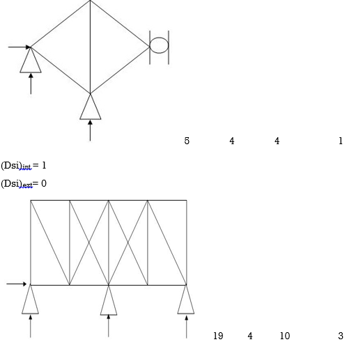
Dsi for Trusses:
(Dsi)Total = (m + R) – (2J)
Where,
M = No of members
R = No of support reactions
J = No of Joints
(Dsi) external = R – 3
(Dsi) internal = (Dsi) total – (Dsi)ext
Dsi = (M + R) – 2j
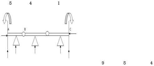
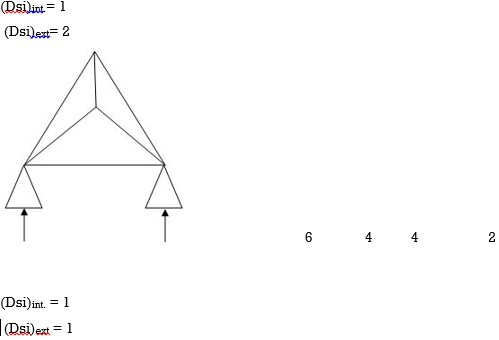
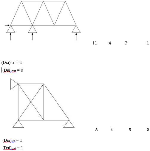
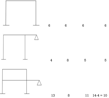
Dsi for Frames:
(Dsi)Total = 3m + R – 3J
(Dsi) external = R – 3
(Dsi) Internal = (Dsi) Total – (Dsi)ext
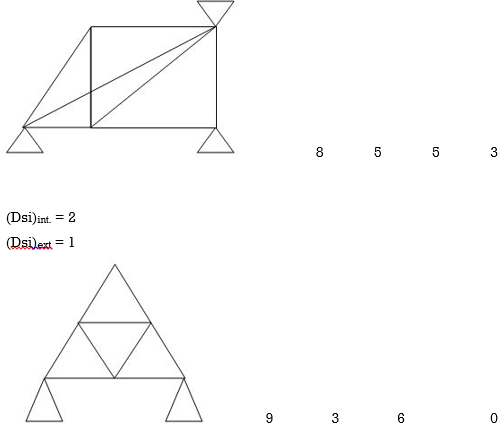
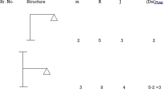

Note:
For Frames:
(Dsi)ext = R – 3
(Dsi)int = 3{ No of closed loops }
(Dsi)total = (Dsi)ext + (Dsi)int
& for Int. pin Reduced (Dsi)Total by (m-1)
Arches
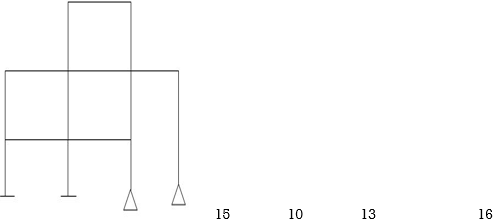
Examples:
1)

R – E = 9-4 = 5
Dsi = 5
2)
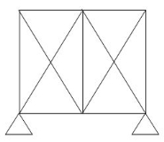
R – E = 5-3
(Dsi)ext = 2
(Dsi)int = 2
(Dsi)Total – (Dsi)ext = (Dsi)Int
Dsi = m + R – 2j
= 11 + 5 – 2(6)
= 4
3)
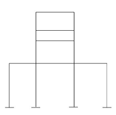
(Dsi)ext = 9
(Dsi)int. = 9
R = 12
m = 16
j = 16
(Dsi)T = (3m + R) – 3j - 18
(Dsi)T = (Dsi) + (R - 3)ext
= 18 – 9
= 92>. Axial deformation of members is neglected.
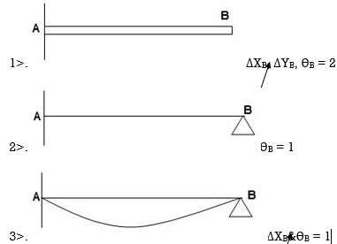
Dki for beams:

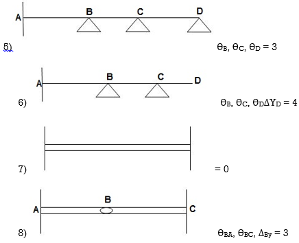

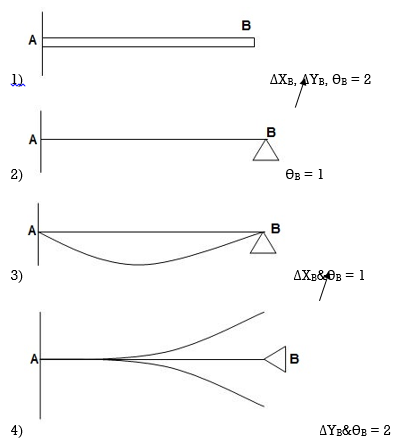
7. Degree of Kinematic Indeterminacy (Dki) :
It is defined as no of unknown joint displacement in the structure.
Note:
Joint means point of support, free end of member and point of intersection of members.
Axial deformation of members is neglected.
Dki for beams :
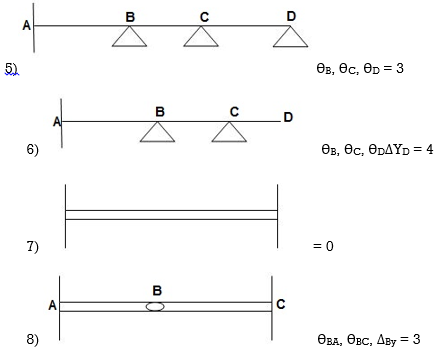

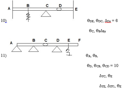
ΔYC, ϴE
ΔYE, ΔYF1, ϴE
Equations of Equilibrium:
Basic structural analysis, our attention is largely focussed on simple examples of plan skeletal structures. As a structure is said to be planar if all its structural elements lie in a single planc (which, we shall consider to be the x-y plane) and if no out-of-plane forces act on the structure.
A structure can be modelled as a planar structure, with all the simplifications that go with it, only if force components F (normal to the x-y plane) and moment components M. (acting in planes parallel to the y-z
The bold notation (without italics) indicates that the variable is a vector quantity. ∑EI-∑EI-∑EK=0 will be satisfied if and only if F, = 0; F, = 0 and F. =0.
The so-called concentrated moment often manifests in practice in the form of a couple of equal and opposite forces, F separated by a lever arm, d. The resultant is a moment of magnitude M=Fd. and My (acting in planes parallel to the 2x plane) do not exist. The effective equations of equilibrium, therefore, reduce in number, from six to three:
∑ Fx = 0, ∑Fy = 0 , ∑Mz = 0
All the forces and moments (if any) lie in the x-y plane. Hence, the moment equilibrium condition summation M, -0 implies that the algebraic summation of all the moments of various forces about any arbitrary point on the x-y plane, plus all the moments (if any), considered either clockwise or anti-clockwise, is equal to zero. It is therefore possible to generate a large number of equations using the condition M, -0, by considering moments about different points on the plane containing the structure.
Some of these moment equilibrium equations will turn out to be inter-related or related to the force equilibrium' equations, F.-0 and F, 0, and it will not be possible to generate more than three linearly independent equations of static equilibrium in a planar structure (and 6 equations in the general case of a space structure).
It is a common practice to consider the two force equilibrium equations and a single moment equilibrium equation (suitably chosen about a point such that one or more of the unknown forces is eliminated in this equation).
However, it may be equally convenient to consider two different moment equilibrium equations (about two different points) plus a single force equilibrium equation, or any other suitable combination.
Key take way:
1. As a structure is said to be planar if all its structural elements lie in a single planc (which, we shall consider to be the x-y plane) and if no out-of-plane forces act on the structure.
2. A structure can be modelled as a planar structure, with all the simplifications that go with it, only if force components F (normal to the x-y plane) and moment components M. (acting in planes parallel to the y-z
3. The bold notation (without italics) indicates that the variable is a vector quantity.
We could view free-bodies as rigid bodies where equilibrium of forces is satisfied withou considering the displaced configuration of the structure.
Thus, while considering the equilibrium of free-bodies, our attention is focussed on the statics of the problem, wi absolutely no regard for the kinematics of the structure.
In other words, in the use of fe bodies, our concern is limited to the static admissibility of the force field, with no regard to the kinematic admissibility of the displacement field.
This is true only for the usual first-order analysis, where equilibrium is considered only in the original undeformed configuration.
However, in reality, the equilibrium is in the deformel configuration, and this may introduce additional force effects associated with geometric nonlineary These effects are usually negligible under service leads, since the deformations are very small to include these secondary effects, we need to resort to a higher-level, so-called 'second-order analysis
Key take way:
1. We could view free-bodies as rigid bodies where equilibrium of forces is satisfied withou considering the displaced configuration of the structure.
2. Thus, while considering the equilibrium of free-bodies, our attention is focussed on the statics of the problem, wi absolutely no regard for the kinematics of the structure.
3. In other words, in the use of fe bodies, our concern is limited to the static admissibility of the force field, with no regard to the kinematic admissibility of the displacement field.
1. Force method:
Force method also known as flexibility method.
The flexibility method is based upon the solution of "equilibrium equations and compatibility equations". There will always be as many compatibility equations as redundant. It is called the flexibility method because flexibilities appear in the equations of compatibility. Another name for the method is the force method because forces are the unknown quantities in equations of compatibility.
DQ=[DQL]+[F][Q]-compatibility equation
DQ=External displacement at redundant position
 Displacement at the redundant position because of applied loading

F=flexibility matrix


Redundant reaction
It is also called as Force Method
In this method, horizontal displacement is neglected
Degree of indeterminancy=R-E
R=Reaction
E=Equilibrium equation
1) Use flexibility Matrix Method
Step 1)


=4-2
=2
The redundant structure is 2.

Zone | Limit | Origin | M |
|
|
CD | 0-2 | C | 0 | 0 | x |
DB | 0-2 | D | -40 | 0 | x+2 |
BA | 0-6 | B |
| x | x+4 |


 = - 11100 /EI


=333.33/


2. Displacement method
It is a matrix method that makes use of the members' stiffness relations for computing member forces and displacements in structures. The direct stiffness method is the most common implementation of the finite element method (FEM).
It is also called a displacement method.
[S]+[D]+[AM]=[AJ]
S = Stiffness Matrix
[D]=unknown joint displacement
i.e. 
AM=Fixed end moments at particular points
AJ=External moment
Important Points


Steps for analysis at stiffness matrix
1 -> Find known rotation i.e. 
2 -> Find fixed end moment
3 -> Find AM value
4 -> Find S matrix
5 -> Put in compatibility equation [S]+[D]+[AM]=[AJ]
6 -> Apply S.D. equation
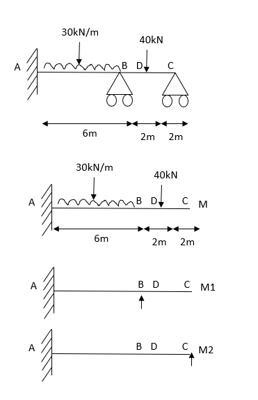
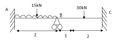
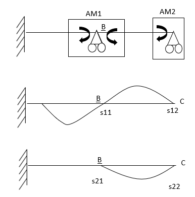
1) Analyze the beam shown in the figure by stiffness method Take EI= constant
Step 1) Find fixed end moment
For Span AB


Span BC


Step 2)

= -5+13.33
= 8.33


Step 3) Use compatibility equation
[S]+[D]+[AM]=[AJ]


Apply SD equation for span AB


2) Analyze the given figure by Stiffness Method

Step 1) Find Dki =
Step 2) Fixed end moments


Step 3) S.D. equation


Step 4) Stiffness Matrix


 =1.33
=1.33


= -3.34

=-13.33
Step 5) Compatibility Equation
[S+[D]+[AM]=[AJ ]


 /EI
/EI
 /EI
/EI


1. Consistent deformation method:
Betti's Theorem can be used to find the redundant support reaction in a propped cantilever beam or a two-span continuous beam with a single degree of static indeterminacy. In this method, the compatibility condition (no deflection at the redundant support location) was applied through the work equation.
We also observed bow this method can be applied to an axially loaded element. Then, we saw how the Conjugate Beam Method can be applied to finding redundant moments at the support locations of fixed beams, propped cantilevers and two-span continuous beams. Here, the compatibility conditions applicable to the actual beams are applied in an analogous manner by satisfying equilibrium conditions in the conjugate beams.
Finally, we observed how the Theorem of Three Moments can be conveniently used to find redundant moments at the support locations of multi-span continuous beams, including the effects of differential settlements, if any.
Built into the three-moment equation is the slope compatibility requirement at the middle support location.
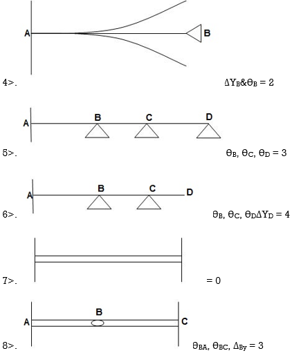
Example: Analysis the propped cantilever beam AB with overhang BC loaded as shown in fig. By the method of consistent deformation, assuming uniform flexural rigidity EI draw the shear force and bending moment diagrams.
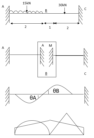
Solution:
The beam is statically indeterminate to the first degree. the effect of the external loads and a unit load X1 = 1 on the primary structure along with the corresponding bending moment diagram ML and m1 as shown in fig.
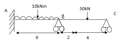
The compatibility conditions to be statisfied is that the net deflection at the support B
D1 should be equal to zero


Where D=
Using the unit load method:
D=
X1 = - 73.45 KN
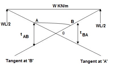
Moment area method (Mohr’s Theorem) :
Principle(I) :
Angle betn tangents drawn to elastic curve at any two points A & B is equal to area of M/EI diagram betn A & B
Principle II :
Position of B on elastic curve with respect to tangent drawn at A is equal to moment of area of M/EI diagram betn A & B about B.
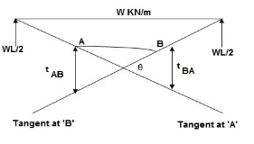

As per principle 1 :ϴ = Area(A)
 Principle 2 :tBA = (A) (xB)
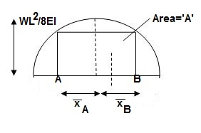
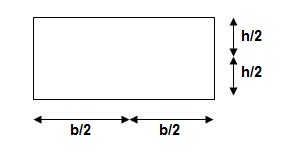
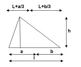
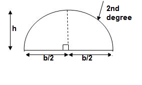
3>. Area and CG
For rectangle

For 20 parabola(udl)
For cubic parabola(UVL Load)
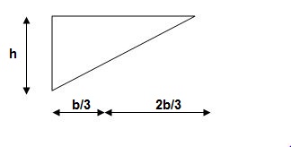
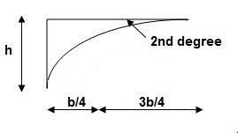

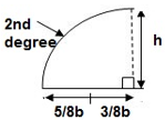
Example :
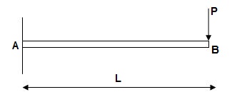
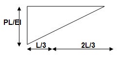
Derive slope & Deflection at free end of cantileve
ϴB = Area of (M/EL)AB
= ½ x L(PL/EI)
 ϴB = PL2/ZEI ( )
tBA = ΔB = (Area)AB x xB
= (PL2/2EI)(2/3L)
 ΔB = PL3/3EI ( )
Exercise :
Ex. 2].
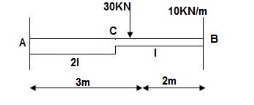
Find ϴC, ΔC
(1). BMD :
BM at c = 0
BMB = (-) 10 x 2 x 1
=(-) 20 KNm
BMA = (-)30 x 3 – 10 x 2(4)
= (-)170KNm
A1 = 30/EI
A2 = 1/2 x 75/EI x 3 = 112.5/EI
A3 = 1/3 x 2 x 20 x 20/EI = 13.33/EI
Elastic curve
(3) Slope & Deflection
ϴC = Area of (M/EI)dia |CA
ϴC = A1 + A2 + A3 = 1/EI { 30 + 112.5 + 13.33 }
 ϴC = 155.83/EI ( )
ΔC = tCA = (A1x1 + A2x2 + A3x3)C
= 1/EI(30 x (3.5) + 112.5(2 + 2/3 x 3) + 13.33 (3/4 x 2))
 ΔC = 575/EI ( )
3>.

Find ϴC&ΔC
E = 2 x 10⁵ MPa
I = 250 x 3503/12
EI = 1.78 x 10⁵ KNm2
1>. BMA = -50 x 4 x (2 + 2)
= - 800 KNm
BMB = -50 x 4 x 2 = -400 KNm
BMC = 0
BMD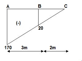
(2) M/EI Dia :
A1 = 100 x 2/EI = 200/EI
A2 = 1/ 2x 100/EI x 2 = 100/EI
A3 = 1/3 x 200/EI x 4 = 266.67/EI
(3). Elastic curve
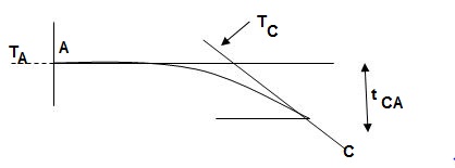
(4). ϴC = Area of (M/EI)AC
= A1 + A2 + A3
= 200 + 100 + 266.67/EI
= 566.67/EI
 ϴC = 3.17 x 10⁻³ rad ( )
 ΔC = tCA = {Area}A-C x xC
= (A1x1 + A2x2 + A3x3)@C
= 200/EI x (4+1) + 100/EI x (4 + 2/3 x 2) + 266.67/EI(3/4 x 4)
= 1000/EI + 533.33/EI + 800.01/EI
=2333.34/EI
= 13.1 x 10⁻³ m
 ΔC = 13.1 mm ( )
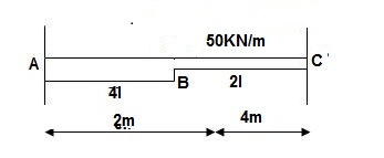
6>. Find ϴC&ΔC
BMD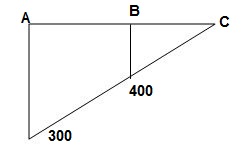
A1 = M/2EI x 3 = 1.5M/EI
A2 = M/EI x 3 = 3M/EI
ϴC = Area (M/EI)A-C
=A1 + A2
ϴC = 4.5M/EI
ΔC = tCA= (A1x1 + A2x2)@c
= 1.5M/EI x (3+1.5) + 3M/EI(1.5)
 ΔC = 11.25M/EI ( )
8>.
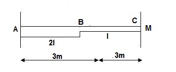
1>. BMA = M
BMB = 0
2>. BMD / ‘M’/EI Dia
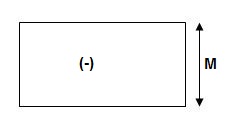
3>. Elastic Curve
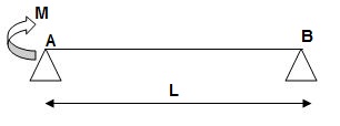
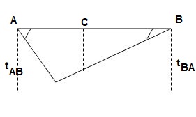
4>. Slope & Deflection
 tAB = {Area}A-B x (xA)
= 1 / 2 x M/EI x L{1/3L}
tAB = ML2/6EI
 tBA = {Area}A-B x (xB)
= 1 / 2 x M/EI x L{2/3 L}
tBA = ML2/3EI
 ϴA ≈ tan(ϴA) = tBA/L = ML/3EI ( )
 ϴB ≈ tan(ϴB) = tAB/L = ML/6EI ( )
tAB/L = C1C3/L/2
C1C3 = tAB/2 = ML2/12EI
 tCB = AreaC-B x (xc)
= 1 / 2 x M/2EI x L/2 x {1/3 x L/2}
tCB = ML2/48EI
ΔC = C1– C2
= C1C3 – C2C3
= ML2/12EI – ML2/48EI
 ΔC = ML2/16EI ( )
10>. ϴC, ΔC= ?

1>. BMA = BMB = 0
BMC = PL/4 = 40 x 4/4 = 40 KNm
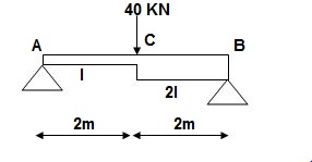
A1 = 1 / 2 x 2 x 40/EI = 40/EI
A2 = 1 / 2 x 2 x 20/EI = 20/EI
3>. Elastic curve
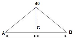
4>. Slope & Deflection
 tAB = (Area)A-B x xA
(A1x1 + A2x2)@A
= 40/EI x (2/3 x 2) + 20/EI(2 + 1/3(2))
= 53.33/EI + 53.33/EI
tAB = 106.67/EI
 tBA = {Area}AB x xB
= (A1x1 + A2x2)@B
= 1/EI{40 x (2 + 1/32) + 20(2/3 x 2)}
= 133.33/EI
 ϴA ≈ tan(ϴA) = tBA/L = 133.33/4EI = 33.33/EI ( )
 ϴB ≈ tan(ϴB) = tanAB/L = 106.67/4EI = 26.67/EI ( )
For ΔC(C1, C2)
tAB/4 = C1C3/2
C1C3 = tAB/2 = 106.67/2EI = 53.33/EI
 tCB = {Area}CB x (xC)
= 20/EI x (1/3 x 2) = 13.33/EI
ΔC = C1C3 – C2C3 = 53.33 – 13.33
ΔC = 39.99/EI
 ΔC = 40/EI ( )
13>.

∑MA = 0
-50 x 1 + VB x 4 + 20 = 4VB = 30
VB = 7.5 KN
VA + VB = 50
VA = 42.5KN
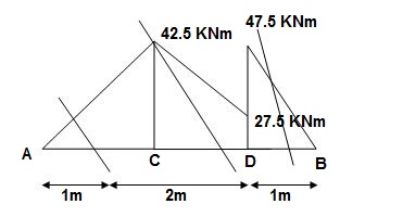
BMA = 0
BMB = 0
BMC = 42.5 x 1 = 42.5 KNm
BMDL = 42.5 x 3 – 50 x 2 = 27.5 KNm
BMDR = 7.5 x (1) = 7.5 KNm
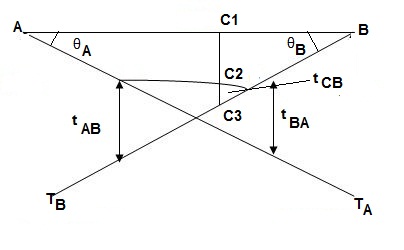
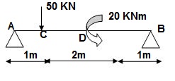
(2).A1 = 1 / 2 x 1 x 42.5/EI = 21.25/EI
A2 = 1 / 2 x 2 x 15/EI = 15/EI
A3 = 27.5/EI x 2 = 55/EI
A4 = 7.5/2EI x 1 = 3.75/EI
3>. Elastic curve : Geometry
4>. Slope &Deflection :
 tAB = {Area}A-B x xA
= (A1x1 + A2x2 + A3x3 + A4x4)@A
= 21.25/EI x [2/3 x (1)] + 15/EI(1 + 1/3 x 2) + 55/EI(1 + 1)+ 3.75/EI(3 + 1/3 x 1)
= 14.16/EI + 25/EI + 110/EI + 12.5/EI
= 161.66/EI
 tBA = Area(B-A) x xB
= {A1x1 + A2x2 + A3x3 + A4x4}@B
= 1/EI{21.25(3 + 1/3 x 1) + 15(1 + 2/3 x 2) + 55(2) + 3.75 x 2/3}
= 218.33/EI
ϴA ≈ tan(ϴA) = tBA/4
 ϴA = 218.33/4EI = 54.58/EI ( )
 ϴB ≈ tan(ϴB) = tAB/4 = 161.66/4EI = 40.41/EI ( )
To find ΔC
tBA/4 = C1C3/1
C1C3 = 54.58/EI
 C1C2 = tCA = Area C.Ax xC
 = A1xC
= 21.25/EI(1/3 x 1)
= 7.08/EI
ΔC = C1C3– C1C2
= 54.58/EI – 7.08/EI
 = 47.5/EI ( )
Steps for Analysis Moment Area method
1>. Find Reqn
2>. Find BM at each pt
3>. Draw M/EI
4>. Draw Elastic curve
 5>. tAB = Area(AB) x xa
 6>. tBA = Area(BA) x xb
 7>. tCA = Area(CA) x xC
C1C3 – C2C3 = C1C2 = ΔC
8>. By similarlΔle, find C1C3
9>. C2C2 find by tCA
1. Conjugate Beam Method
The conjugate beam method is another method for solving the problems on deflections in beams. The relationships between the loading, shear, and bending moments are given by
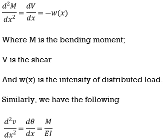
If we compare the above two equations, it indicates that if  is loading on an imaginary beam, the resulting shear and moment in the beam are the slope and displacement of the real beam, respectively. This imaginary beam is known as the conjugate beam and its length is same as the original beam.
Conjugate beam method consists of two major steps.
Step 1: Set up an additional beam, known as conjugate beam.
Step 2: Determine the shearing forces and bending moments in the conjugate beam.
The loading diagram showing the elastic loads that are acting on the conjugate beam is nothing but the bending moment diagram of the actual beam and divided by the flexural rigidity EI of the actual beam. If the bending moment is sagging, the elastic load is taken downward.
For each existing support condition of the actual beam, there is a corresponding support condition for the conjugate beam. The following table shows the corresponding conjugate beam for different types of actual beams.
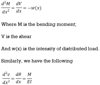
The actual beam and also the conjugate beam are always in static equilibrium condition.
The slope of the centerline of the actual beam at any cross-section is equal to the shearing force at the corresponding cross-section of the conjugate beam.
This slope is taken positive or in anti-clockwise direction if the shearing force is positive in order to rotate the beam element in anti-clockwise direction in beam convention.
The deflection of the centerline of the actual beam at any point is equal to the bending moment of the corresponding conjugate beam at the corresponding point.
This deflection is taken downward or negative if the bending moment is positive in order to cause top fiber in compression in beam convention.
The positive shearing force and bending moment are shown in the Figure below:

Positive shearing force or bending moment
Example 1: Determine the slope and deflection of point A of the of a cantilever beam AB of length L and uniform flexural rigidity EI. A concentrated force P is applied at the free end of beam.
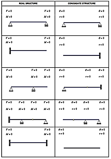
Solution:
The conjugate beam of the actual beam is shown in Figure 4.8(b). A linearly varying distributed upward elastic load with intensity equal to zero at A and equal to PL/EI at B. The free-body diagram for the conjugate beam is shown in Figure 4.8(c). The reactions at A of the conjugate beam are given by

The slope at A, 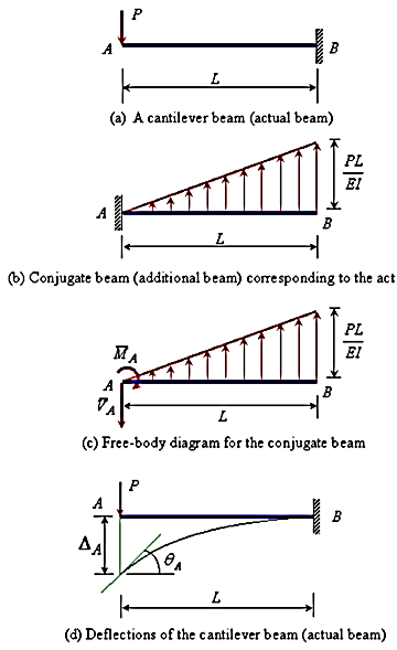 and the deflection
  at the free end A of the actual beam in Figure (d) are respectively equal to the shearing force
  and the bending moment
  at the fixed end A of the conjugate beam in Figure (d)
Hence,

Example 2: Determine the deflection at the free end of the beam shown in Figure below, using conjugate beam method.

Solution:
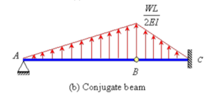
The corresponding conjugate beam and loading are shown in Figure (b).

The loading is upward linearly distributed load with maximum value of 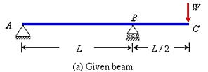 at B. Taking moment about point B, the vertical reaction at A in the conjugate beam is given by
The bending moment at C (by taking moment about C) is given by

Hence, the deflection of point C will be equal to 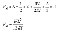 in the downward direction.
2. Theorem of three moments
Our experience with two-span continuous beams, using the Conjugate Beam Method, shows us that the bending moments in the beam at the intermediate and fixed end supports can be conveniently chosen as the redundants.
Usually, while analysing multi-span continuous beams by popular force-based methods like the Method of Consistent Deformations.
It is more common to use the intermediate support reactions as the redundants. Such a choice is found to be especially suitable when there are known support settlements to be accounted for in the compatibility equations.
The choice of the beam moments at the various supports, however, presents a simpler and more efficient alternative, while using one of the earliest known methods of analysis of continuous beams, originally due to Clapeyron in 1857, and later extended to solving beams with differential settlernents by Otto Mohr in 1860. The original form of the method is known as Clapeyron's Theorem, but the more generalised version is often simply referred to as the theorem of three moment.
Three moments Theorem
* Concepts – i) Moment at simply supported end is always zero.
ii) Moment at fixed & intermediate is created
* Formula :

For span ABC

 MAl1 + 2MB (l1+l2) + Mcl2 = 6a1x1 + 6a2x2
l 1 l2
For different I -


 MAl1 + 2MB (l1+l2) + Mcl2 = 6a1x1 + 6a2x2
I1 I1 I2 I2 l1I1 l2 I2
Area due to loading
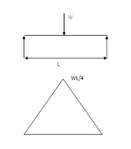
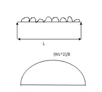
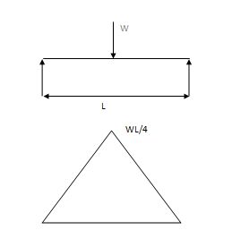
Case (1) Both ends are simply supported end
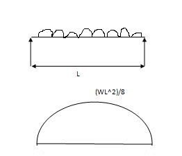
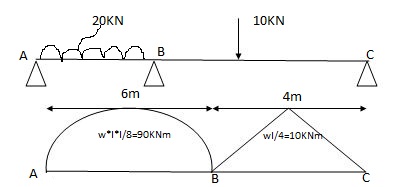
2) 6a1x1 = A = 2 x 6 x 90 = 360 A2 = 1 x 4 x 10 = 20m2

 3 2
3 2


 x1 = 6/2 = 3m x2 = 4/2 = 2m

 6a1x1 = 6 x 360 x 3 = 1080
l1 6
6a2x2 = 6 x 20 x 3 = 60

 l2 4
l2 4
3) Apply 3 moments thm
For spon ABC

 MAl1 + 2MB (l1+l2) + Mcl2 = 6a1x1 + 6a2x2
l 1 l2
MA = MC = 0 l 1=6m l 2 =4m
0 + 2MB (6+4) + 0 = 1080 + 60
2MB (10) = 1140
aw S.F.D.
Due to external load
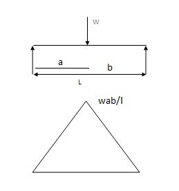


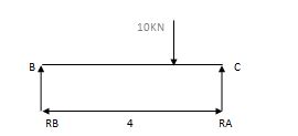
 RA = Wl = 20x6 = 60 kn RB = W = 10 = 5 kn
2 2 2 2


 RB = Wl = 20x6 = 60 kn RB = W = 10 = 5 kn
2 2 2 2
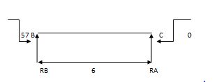
2) Due to moment

EMA=0 EMB = 0

 RB x 6 – 57 = 0 RC x 4 + 57 = 0
RB = 9.5 KN RC = 14.25 KN
Efi = 0
 RA + RB = 0 RC + RB = 0
RA = - 9.5 KN RB = 14.25 KN
Total Rean
RA = 50.5 KN
RB= 69.5 KN
RC = 5-14.25 = - 9.25 KN
RB = 5 + 14.25 = 19.25 KN

-2 One end is fixed & other is Hinge
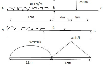


 A1 = 2 x wl2 x 12 = 2 x 30 x 122 x 12 = 4320 mm2
3 3 8
 x1 = l1 = 12 = 6 = 6m

 2 2
2 2

 A2 = 1 x wab x 12 = 1 x 240 x 4 x 8 x 12 = 3840 mm2
 2 2 12

Apply 3 moment Thm
A’AB

 MA1l1 + 2MA ( l1+ l1 ) + MB l1 = 6a1x1 + 6a1x1
l1 l1
 0 + 2MA ( 0+12) + 12MB = 0 + 6 x 4320 x 6
12

 24MA + 12MB = 12960 (1)
Span ABC

 MAl1 + 2MB ( l1+ l2 ) + MCl2 = 6a1x1 + 6a2x2
l1 l2

 12MA + 2 MB (12 + 12) + 0 = 6 x 4320 x 6 + 6 x 3840 x …
12 12

 12MA + 48 MB = 24480 (2)
Add eqn. (1) & (2)
MA = 325.71 KNM
MB = 428.57 KNM
Draw S.F.D.
1) Due to external load

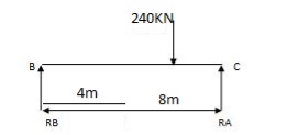


 RA = wl = 30 x 12 = 180 KNW RB = wb = 160 KN
2 2 l


 RB = wl = 30 x 12 = 180 KN RC = 120 KN = wa =
2 2 l
2) Due to moment

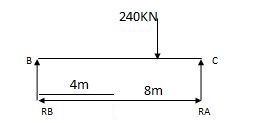
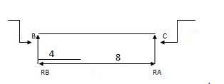
EMA=0 EMB=0
325.71 – 428.57 + RB x 12 = 0 428.57 + RC x 12 = 0

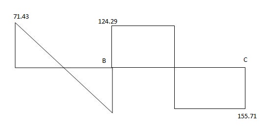
RA = 180 – 8.57 = 171.43 KN
RB = 180 + 8.57 = 188.57 KN
RB = 160 + 35.71 = 124.29 KN
RC = 120 + 35.71 = 155.71 KN

(3) Both ends are fixed

A1 = 0
 xi = 0


 A1 = 2 x wl2 x 6 = 112.5 A2 = 2 x wl2 x 5 = 125
 3 8 3 8


 x1 = 6/2 = 3 x2 = 5/2 = 2.5
A12 = 0 x12 = 0
Span A1AB

 MAl1+ 2MB (l11 + l1 ) + MBl1 = 6a11x11 + 6a1x1
l11 l1
 0 + 2MA (0+6) + 6MB = 0 + 6 x 112.5 x 3
6

12MA + 6MB = 337.5
Span ABC

 MAl1+ 2MB (l11 + l1 ) + MC = 6a1x1 + 6a2x2
l1 l2

 6MA + 2 MB ( 6+ 5) + MC x 5 = 6 x 112.5 x 3 + 6 x 175 x 2.5
6 5

 6MA + 22MB + 5MC = 712.5 (2)
BCC

 MBl2+ 2MC (l2 + l12 ) + MC1l12 = 6a2x2 + 6a12x12
l2 l12
5MB + 2MC ( 5+0) + 0 = 6 x 125 x 2.5


 5MB + 10 MC = 375 (3)

MA = 17.33 KNM
MB = 21.59 KNM
MC = 26.70 KNM
Rean due to external load
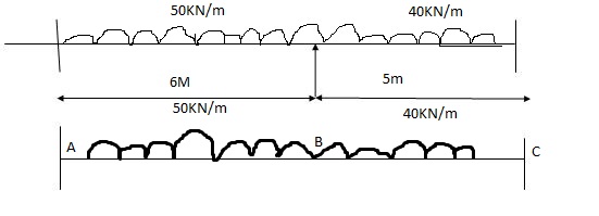


 RA = wl = 150 RB = wl = 100 KN
2 2

 RB = wl = 150 RC = wl = 100 KN
2 2
Rean due to moments


17.33 – 21.59 + RB x 6
RB= 1.022
RB = 0.71 RA = 0.71 RC = 1.022
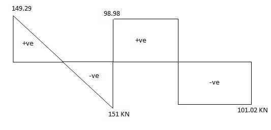
Total Rean
RA = 150 – 0.71 = 149.29 KN
RB = 150 + 0.71 = 150.71 KN
RB = 100 – 1.02 = 98.98 KN
RC = 100 + 1.02 = 101.02 KN


4 - Overhung Numerical


 A1 = 1 x 3 x wab A2 = 1 x wl x 4
2 l 2 4

 1 x 3 x ( 20 x 1 x 2) = 20m2 A2 = 60 m2
2 3
 x1 = 4 /3 3 +1 = 4/3 = 1.33
3
s
Span ABC

 MAl1+ 2MB (l1 + l2 ) + MCl2 = 6a1x1 + 6a2x2
l1 l2

 0 + 2 MB ( 3+ 4) + 15 x 4 = 6 x 20 x 1.33 + 6 x 60 x 2
3 4
 14MB + 60 = 53.2 + 180
MB = 173.2 KN
References:
1. Theory and Problems in Structural Analysis by L Negi, Mc Graw Hill
2. Structural Analysis by T.S. Thandamoorthy, Oxford University Press
3. Basic Structural Analysis by C S Reddy, McGraw Hill
4. Elementary Structural Analysis by Norris and Wilber, McGraw Hill
5. Structural Analysis by Aslam Kassimali, Cengage Learin
6. Analysis by R.C. Hibbeler, Pearson Education


