Unit - 2
Energy theorems and its application
Energy theorem:
These are methods primarily based totally on linear elastic conduct and conservation of electricity, Energy U = Fx/2 = F2/2k wherein F is the implemented pressure, x is the space moved within side the route of the pressure at its factor of utility and okay is the elastic stiffness of the part, once more within side the route of the pressure at its factor of utility., i.e., the work done via way of means of outside forces equals the electricity saved within side the structural below.
Application:
1. Work energy theorem could be very beneficial in reading conditions in which an inflexible frame movement below numerous force.
2. We recognize that an inflexible frame can't shop capacity electricity in its lattice because of inflexible structure, it could handiest own kinetic electricity.
3. The work accomplished through any pressure performing on an inflexible frame is identical to the extrade in its kinetic electricity. This is the premise of labor electricity equation for inflexible bodies.
4.In style of instances whilst a spring is hooked up to frame then in case whilst a spring is compressed or elongated, it absorbs power and shops in shape of elastic ability power that's because of the negative work finished through spring at the connected frame.
5. Work finished through spring will constantly be subtracted from frame power if it absorbs power and can be brought to frame power if it releases power.
Key takeaway:
1. These are methods primarily based totally on linear elastic conduct and conservation of electricity, Energy U = Fx/2 = F2/2k
2. Work energy theorem could be very beneficial in reading conditions in which an inflexible frame movement below numerous force.
3. We recognise that an inflexible frame can't shop capacity electricity in its lattice because of inflexible structure, it could handiest own kinetic electricity.
Q.1) EI = 17250 Kn.m2 find strain energy?

Solution:
∑MA = 0
30 x 2 – RB x 4 = 0
RB = 15
VA = VB = 15 KN
BMC = BMD = 15(1) = 15 KN.M
BMC = 15(2) = 30 KN.M
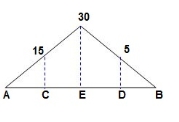
‘M/EI’ Dia.
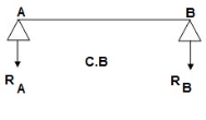
C.B
A1 = 1 / 2 x 1 x 15/EI = 7.5/EI
A2 = 2 x 7.5/EI = 15/EI
A3 = 1 /2 x 2 x 7.5/EI = 7.5/EI
A4 = 1 / 2 x 15/EI x 1 = 7.5/EI
Analysis of conjugate beam:
∑MA = -RB (4) + 1/EI {7.5(2/3 x 1) + 15(2) + 7.5(2) + 7.5(3 + 1/31)} = 0
= - RB x 4 + 1/EI [ 5 + 30 + 15 + 25] = 0
RB x 4 = 75/17250
RB = 18.75/EI
∑fy = 0
-RA + RB + A1 + A2 + A3 + A4 = 0
RA = 18.75/EI
RA = RB = ½ {A1 + A2 + A3 + A4} = 18.75/EI
Slope & Deflection:
(ϴA) R.B = (SFA)C. B = (-)18.75/EI

 = 18.75/EIxC = 1.086 x 10⁻³radxC

 (ϴB) R.B = (SFB)C. B = 18.75/EIxC = 1.086 x 10⁻³ rad xC
(ΔE) R.B = (BME)CB
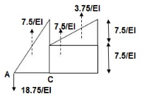
(BME)CB= 1/EI { -18.75 + 7.5(1 + 1/3 x 1) + 7.5(0.5) + 3.75 (1/3 x 1)}
=1/EI {-22.5}

 ΔE = 22.5/EI xC = 1.304 mm xC
Key takeaway
1. Find Reactions
2. M/EI Diagram
3. C.B
4. Analysis of Conjugate Beam
5. Slope and Deflection
Principle of Virtual Work is a most powerful principle, having a wide range of applications in mechanics. We will encounter this principle in its many forms in a wide ty of applications, beginning with the determination of the force response in a statically structure.
Work is basically an abstract concept, expressing a product of a force and an is placement, and has units of Nm or Joule. It therefore symbolizes a combined idea of force and displacement, both of which are important to us in determining structural response.
The virtual, which means imaginary, emphasizes the abstraction in the concept, and provides deviation from the usual physicists' concept of work (which is sometimes referred to in mechanics as real work).
The concept of virtual work provides a bridge interconnecting the firce field and the displacement field in a structure, and can be used to unveil the hidden laws that govern the load response behavior of any structure.
The Principle of Virtual Work, as we shall see, can help us establish equations that relate to equilibrium in the force field, compatibility in the displacement field and force-displacement (stiffness and flexibility) relationships.
We shall now state the more generalized Principle of Virtual Work, applicable to deformable structural systems.
Bernoulli's Principle of Virtual Displacements is but a special case of this more generalized principle. As we are now dealing with deformable bodies, we must reckon with the virtual work done by internal forces (internal virtual work) and distinguish this from the work done by external forces (external virtual work). We shall use the term conjugate to link the propriate displacement corresponding to the force under consideration.
It is as though the free and conjugate displacement (or displacement and conjugate force) share a conjugal relationship, as in a marriage. They are coupled by the fact that they have the same location od sense of direction.
Thus, an external vertical force F acting downward at a point A in a structure is conjugate with a deflection D, which also acts downward at the same point A Similarly, an internal tensile force N, in the bar of a truss is conjugate with an elongation the same bar. The product FD, is a measure of external virtual work, and the product N is a measure of internal virtual work.
A very important point to appreciate here is that there need not be any cause-effect relationship linking F and D. or N, and e, as far as virtual work calculations are concerned.
The force field (system of external and internal forces) and the displacement field (conjugate system of displacements/deformations) can be completely independent of each other. They can be visualized as two separate systems acting on the same structure (at separate times, of course), or as two separate systems acting on identical structures.
By combining the force field in one system with the displacement in another system, we are trying to discover some hidden laws that govern the statics and kinematics of the structure under consideration.
Let us consider a discrete system, such as a truss, in which the force field comprises external forces (represented by the vector Fa) acting on the overall free-body of the truss and the internal axial (normal) forces (represented by the vector FN) acting in the various bars of the truss.
Thus, Fe denotes the external force acting at the coordinate (joint location with a particular direction) and V, denotes internal tensile force in the bar. The conjugate displacement corresponding to F is denoted by D and that corresponding to N (F) is denoted by e, (D). As emphasized earlier, the force field (F. Ft) can be completely independent of the displacement field (De:D).
Let us assume that the force field belongs to system I and the displacement field belongs to system II. The only mandatory requirement is that the force field must satisfy equilibrium conditions, and the displacement field must satisfy internal compatibility requirements. Any statically admissible system of forces is acceptable in system I, and any internally kinematically admissible system is acceptable in system II in applying the principle of virtual work.
Key takeaway:
1. Principle of Virtual Work is a most powerful principle, having a wide range of applications in mechanics.
2. We will encounter this principle in its many forms in a wide ty of applications, beginning with the determination of the force response in a statically in structure.
3. Work is basically an abstract concept, expressing a product of a force and a displacement, and has units of Nm or Joule.
Unit Load Method is also named as virtual(digital) work approach. Digital work is a process for computing a single factor of deflection at any factor on a shape. The approach lets in the fashion dressmaker to consist of in deflection computations the influence of assist settlements, temperature change, and fabrication errors. These different outcomes consist of the actual loads, temperature change, assist agreement and so forth. In different words, the deflected form because of the actual forces is thought to be the digital deflected form of the dummy shape, and the precept of labor and power is applied
The Unit Load Method When the precept of digital work is used to calculate the displacement at a coordinate, the gadget of outside forces, is selected in order to consist simplest of an unmarried unit pressure at coordinate Unit Load Method for Deflection Calculation
The unit load approach is also known as the approach of digital work. The primary equation to calculate displacement (whether or not translational or rotational) at a given factor of a beam or body is given as,
A = f M m dx A = f El
Where, M Moment at any factor in a shape because of implemented hundreds m Moment at any factor in a shape because of the unit load (pressure or second) at the focal point similar to the parameter of interest (deflection or rotation) E Modulus of elasticity I Moment of inertia of the go phase of a member To compute a factor of deflection with the aid of using the approach of digital work, the fashion dressmaker applies a unit pressure to the shape on the factor and within side the path of the desired displacement. This pressure is frequently referred to as a dummy load the displacement it will go through is produced with the aid of using different outcomes.
Key takeaway:
1. Unit Load Method is also named as virtual(digital) work approach.
2. Digital work is a process for computing a single factor of deflection at any factor on a shape.
3. The approach lets in the fashion dressmaker to consist of in deflection computations the influence of assist settlements, temperature change, and fabrication errors.
1. Betti's law:
Consider a linear elastic structure, subject to two different force-displacement conditions, which we may refer to as systems I and II Let (Fi) and (F) denote the sets of external forces acting on these two systems, and let (D) and (Da) denote their conjugate displacements. This is illustrated in Fig. for the case of a simple flexural member. Six coordinate points are identified, for convenience, as shown in Fig. The external forces (applied loads and support reactions), as well as deflections, in two different systems involving the same beam are shown in Figs. respectively. The two force fields must necessarily satisfy equilibrium (considering the free-body of the beam). Similarly, the two displacement fields must satisfy internal compatibility, although they may have different boundary conditions.
Applying the Principle of virtual work, by combining the force field in system I with the displacement field in system II,

where M(x) and (x) denote the bending moment and curvature at x in system I and II respectively. As the beam is assumed to be linearly elastic,
M.(x) 
where M (1) is the bending moment at x in system II and El is the flexural rigidity of the Substituting Eq

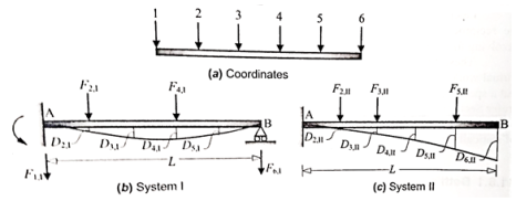
Similarly, combining the force field in system II with the displacement field in system I it can be shown that
ΣΕ, D, - MM EI
Comparing Eqs.1 and 2 and noting that the expression on the right-hand-side is identical, it follows that we arrive at the same equation, if we use a linear clastic truss or frame instead of the beam in Fig. In all cases, in which there is only one type of action involved in the computation of internal work (either bending moment or axial force), there is a reciprocal nature reflected in the expression for internal virtual work. In the case of a truss, it takes the following form
where N and N denote the axial force in the bar in systems I and II respectively, and f denotes the axial flexibility of the bar.
Betti's theorem states that the total external virtual work associated with forces (F) in system I and the conjugate displacements (D) in system II is equal to that associated with forces (F) in system II and conjugate displacements (D) in system I in a linear elastic structure.
2. Maxwell's law:
It is easy to derive Maxwell's theorem from Betti's theorem, although historically, Betti started with Maxwell's theorem and extended its application. The main difference between Maxwell's and Betti's formulations lies in the fact that Maxwell dealt with the application of ne load at a time, whereas Betti considered multiple loads acting at a time.
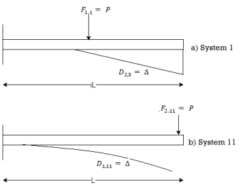
When considerations are limited to two coordinates only. Consider the cantilever ss beam AB in Fig. with the same load P acting at two different locations ('1' and '2') in system I and II respectively. Let the deflection D, at the coordinate '2' due to the load P acting at '1' in system I be equal to A, as shown in Fig.
Let Din denote the deflection at the coordinate 'I' due to the load P in system
shown in fig.
Applying Betti's theorem (Eq.)
Fu Du-F D
PD PA
⇒Din = A
This establishes the reciprocal nature of P and A at two different locations.
Maxwell's reciprocal theorem states that in a linear elastic structure, if a load F acting at some coordinate location '1' causes a displacement D at some other coordinate location '2', then the same displacement D will occur at '1', if the load Facts at 2' in a separate loading condition.
It may be noted that the load F may be either a concentrated force (with N units) or a concentrated moment (with Nmm units), and the displacement could be a translation (with mm units) or a rotation (in radians). It is also possible to have a reciprocal relationship between a force / displacement and moment/rotation. This can be easily understood by the concept of flexibility coefficient.
1. Castiglione’s1sttheorem:
It states that displacement at a point of application of load in the direction of load is equal to partial derivative of strain energy of structure with respect to load.
1]. ӘU/ӘQi = Δj
U = strain energy
Qj = Force in the direction j
Δj = Displacement in the direction j
2]. Strain energy: UAxial force = ∫L0P2dx/2EA
UB.M = ∫L0M2dx/2EI
UTorsion = ∫L0T2dx/2GJ
Deflection = translation
3]. Procedure of displacement analysis by Castiglione’stheorem:
Step 1:
Apply imaginary load ‘Q’ at section where displacement is required.
Note:
1. For horizontal translation apply ‘Q’ in horizontal direction.
For vertical translation apply force Q in vertical direction
2. For finding ‘slope’(rotation) apply couple Q.
Step 2: Find support reactions and draw member F.B. D’s
Step 3: Prepare table:
Zone origin limits EI M ӘM/ӘQ
Step 4: Find displacement using Δj = ∫L0M/EI{ӘM/ӘQj} dx
Find ΔB:


Zone Origin Limits EI M ӘM/ӘQ
BA B 0 to L EI –Q(x) – W(x2/2)-x
ΔB = ∫L0 M/EI(ӘM/ӘQ) dx = ∫L0{-W(x2/2)} (-x) dx
= W/2EI{x4/4} L0
 ΔB = WL4/8EI( )
Find
1]. Vertical deflection at ‘c’,
EI = constant

M Diagram
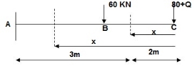
From above Fig:
Table
Zone Origin limits EI M ӘM/ӘQj
CB C 0-2 EI -(80 + Q) x - x
BA C 2-5 EI -(80 + Q) x - x-60(x-2)
ΔC = ∫20-(80)x/EI {-x} dx + ∫52{80x – 60(x-2) (-x) dx/EI}
= ∫2080x2/EI dx + ∫52{80x2 – 60x2 + 2x} dx/EI
= 1/EI {213.33 + 4200}
 ΔC = 4413.33/EI ( )
2] Find vertical deflection at point C
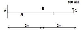
M Diagram
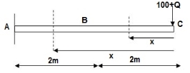
Zone Origin Limit EI M ӘM/ӘQ
CB C 0 – 2 EI - (100 + Q)x -x
BA C 2 – 4 EI -(100 + Q)x -x
ΔC = ∫20 – 100x/EI(-x) dx + ∫42 -100x/EI(-x) dx
= ∫20100x2/EI dx + ∫42100x2/2EIdx
= 266.66 + 1866.6/2 = 266.66 + 933.33
For cantilever always write load from free end. For simply write load from supports.
ΔC = 1200/EI
3] Find slope at deflection ‘A’, deflection at ‘C’.
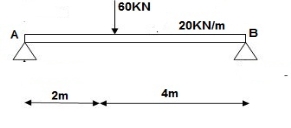
M Diagram
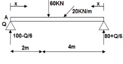
Reactions in M dia.
∑MA = VB (6) – 20 x 6 x 3 – 60(2) – Q = 0
VB = 80 + Q/6
∑Fy = VA + VB – 60 – 20 x 6 = 0
VA = 100 – Q/6
Zone Origin limits EI M ӘM/ӘQ
AC A 0 – 2 EI (100-Q/6)(x) 1 – x/6+ Q – 20(x2/2)
BC B 0 – 4 EI (80+Q/6)(x)-20x2/2 x/6
ϴA = ∫20{100(x) – 10x2} {1-x/6} dx/dEI + ∫40{80x – 10x2}x/6dx/EI
= 1/EI {135.55 + 177.78}
 ϴA = 313.32/EI( )
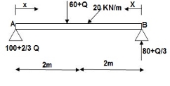
∑MA = VB (6) – 20(6)(3) – (60 + Q)2 = 0
VB = 80 + Q/3
∑Fy = VA + VB – (60 + Q) – 20(6) = 0
VA = -80 – Q/3 + 60 + Q + 120 = 0
VA = 100 + 2/3Q
4]. Find a deflection at a point C

i) M Diagram
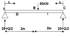
Zone Origin Limit EI MӘM/ӘQ
AC A 0 – 2 EI (25 + Q/2)x x/2
BC B 0 – 2 EI (25 + Q/2) x x/2
ΔC = ∫20(25x) x/2dx/EI + ∫2025x(x/2) dx/2EI
= 33.33 + 16.66/EI
 ΔC = 50/EI( )
1]. Find deflection at D
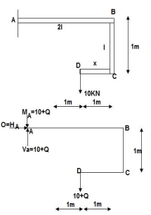
∑MA = MA – (10+Q) (1) = 0
MA = 10 + Q
∑Fy = VA – (10 + Q) = 0 VA = 10 + Q
∑Fx = HA = 0
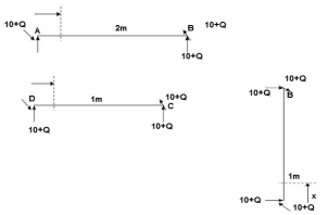
Zone origin limits EI M ӘM/ӘQ
AB A 0 – 2 2EI (10+Q)x-(10+Q) x-1
CB C 0 – 1 EI -(10 + Q) -1
DC D 0 – 1 EI -(10 + Q)x - x
ΔDy = ∫20(10x - 10) (x-1) dx/2EI + ∫10 -10(-1) dx/EI + ∫10 -10x(-x) dx/EI
 = 3.33 + 10 + 3.33/EI
ΔDy= 16.66/EI( )
2. Castiglione’s second theorem
Basics (1)
i) Beam fixed at both end is called as Fixed beam
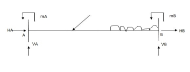
ii) Fixed beam is statically indeterminate
Number of unknown Reactions = R=6
Number of Equilibrium equation = E=3
Dsi – R-E = 6-3 =3
Note:
For beam subjected to vertical loads lonely-horizontal reactions are zero.
For Fixed beam subjected to vertical loads only.
Number of unknown reactions = R=4
Number of equilibrium equation = E=2
Dsi – R-E = 4-2 =2
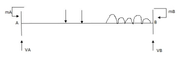
For vertically downward load fixed and moments are begging in nature.


4) Advantages of fixed beam
5) For fixed beam,
Tangents drawn at both ends are horizontal therefore angle betn tangents is equal to area of  Diagram is equal to zero.

1= Area  ‘Dia’ =0
Position of B with respect to tangent drawn at A
BA = Area  Dia
Dia =0
=0
Key takeaway
1. ӘU/ӘQi = Δj
2. Strain energy: UAxial force = ∫L0P2dx/2EA
3.Procedure of displacement analysis by Castiglione’s theorem
Step1: Apply imaginary load ‘Q’ at section where displacement is required.
Step2: Find support reactions and draw member F.B. D’s
Step 3: Prepare table:
Zone origin limits EI M ӘM/ӘQ
Step 4: Find displacement using Δj = ∫L0M/EI {ӘM/ӘQj} dx
The minimal overall capability strength precept is an essential idea used in engineering. It dictates that at low temperatures a shape or frame shall deform or displace to a role that (locally) minimizes the overall capability strength, with the misplaced capability strength being transformed into kinetic strength. His general capability strength is the sum of the elastic stress strength, U, saved within side the deformed frame and the capability strength, V, related to the implemented forces
Π = U + V (1)
This strength is at a desk bound function whilst an infinitesimal version from such function entails no alternate in strength
δ Π = δ (U + V) = 0 (2)
The precept of minimal general capability strength can be derived as a unique case of the digital work precept for elastic structures issue to conservative forces.
The equality among outside and inner digital work (because of digital displacements) is:
∫ S t δ u T T d S + ∫ V δ u T f d V = ∫ V δ ϵ T σ d V (3)
In the unique case of elastic bodies, the right-hand-aspect of (3) may be taken to be the alternate, of elastic stress strength U because of infinitesimal versions of actual displacements. In addition, whilst the outside forces are conservative forces, the left-hand-aspect of (3) may be visible because the alternate within side the capability strength function V of the forces. The function V is described as
V = − ∫ S t u T T d S − ∫ V u T f d V
Where in: the minus signal implies a lack of capability strength because the force is displaced in its direction. With those subsidiary conditions, (3) becomes:
− δ V = δ U
This leads to (2) as desired. The variation shape of (2) is frequently used as the idea for growing the finite detail approach in structural mechanics.
Key takeaway:
1. The minimal overall capability strength precept is an essential idea used in engineering.
2. It dictates that at low temperatures a shape or frame shall deform or displace to a role that (locally) minimizes the overall capability strength, with the misplaced capability strength being transformed into kinetic strength.
3. His general capability strength is the sum of the elastic stress strength, U, saved within side the deformed frame and the capability strength, V, related to the implemented forces Π = U + V
References:
1. Theory and Problems in Structural Analysis by L Negi, Mc Graw Hill
2. Structural Analysis by T.S. Thandamoorthy, Oxford University Press
3. Basic Structural Analysis by C S Reddy, McGraw Hill
4. Elementary Structural Analysis by Norris and Wilber, McGraw Hill
5. Structural Analysis by Aslam Kassimali, Cengage Learin
6. Analysis by R.C. Hibbeler, Pearson Education