Unit - 3
Analysis of redundant plane trusses
Consider the truss which has hinged supports at both ends.
External indeterminacy Number of unknown reaction (R) -equilibrium equation (E) 04-03= 01 Internal indeterminacy=m-2j+3-9-2x6+3=0
Degree of static indeterminacy = 01
Assuming vertical component at D as a redundant force
Then, restraint in that direction is to be removed and vertical force R, is treated as an additional unknown force acting on that structure. The condition for consistency is that turns of should have zero vertical displacement to represent the given truss.
As the truss is a determinate truss, its displacement can be evaluated and the consistency condition can be imposed on it.
For finding the displacements, unit load method may be used because this method is ideally suited for finding the displacement in trusses.
Now, the total displacement in the truss may be split into two parts:
One due to the given loadings (i.e. P- Analysis) and the ether due to the redundant force Rp Let the forces developed in the members of the truss, due to given loadings be P Analysis and that due to unit load at D in the direction of Ro be K.
Then According to unit load method, the vertical displacement of B due to the given loading is given by
Vertical displacement due to RD

The displacement of B

But according to consistency condition the vertical displacement is equal to zero


Procedure to analyze the indeterminate truss of one degree redundancy
Step 1) Find degree of indeterminacy
Step 2) Select the redundant member
Step 3) Remove the redundant member and find the force P is members of the truss for the given load system
Step 4) Remove the load given system
Step 5) Find  and
and  for each member
Step 6) Find redundant force
Step 7) Find the force in any member by the reaction
Problems:
Solution:
Step 1) Degree of redundancy
R-E= 3-3 = 0
Degree of internal redundancy= m-(2j-3)= 6-(2x4-3)=1
Total degree of redundancy= 0+1 = 1
Step 2) Let AD be the redundant
Remove member AD
Step 3) P forces
a. Consider joint A in equilibrium


b. Consider joint D in equilibrium


K forces
Remove external load
Apply pair unit load


B. Consider joint C in equilibrium


Find 
Member | P | K | PK | K^2 | Final forces (F) =P+KR | Remark |
AB | 0 | +0.71 | 0 | 0.504 | -0.62 |
+ Tension -Compression |
AC | 0 | +0.71 | 0 | 0.504 | -0.62 | |
AD | 0 | -1 | 0 | 1 | 0.88 | |
BD | 5 | +0.71 | +3.55 | 0.504 | 4.37 | |
BC | 0 | -1 | 0 | 1 | 0.88 | |
CD | 0 | -0.71 | 0 | 0.504 | -0.62 |


Step 6) Find redundant force R

Step 7) Final forces
Final force in all member is given by F= P+KR
Final force is shown in table
Key takeaway:
Steps:


Trusses are simply defined as triangulation of members to make the stabilized structure. Triangulation is the stable configuration mathematically. Generally, a truss has the members called as top chord, bottom chord, vertical chord and diagonal chord. The main functions of the trusses are:

There are some basic assumptions in the designing process. It should be clarified that the construction of the trusses should conform with the design assumptions to avoid the unwanted failures due to the dispersion of the forces and loads.
Following are the assumptions in truss design.
TYPES OF TRUSSES
Simple Truss: It is possible to create a simple truss by joining three bars together to form a triangle. We can increase the size of the truss by adding two more members with an additional joint. By repeating this process, we can develop simple trusses with different shapes as shown below. The triangular building block assures internal stability of the truss structure as it is increased in size.

Although it is possible to have non-triangular cells in a simple truss, internal stability will not be guaranteed in that case.
Compound Truss: A compound truss is made up of simple trusses joined together to form a larger truss. The figure below shows a compound truss consisting of two simple trusses joined by a common joint and a bar. It is also possible to have multiple simple trusses joined together to create a larger compound truss. The connection of simple trusses then becomes a design issue determined based on the size of the resulting compound truss. Compound trusses are commonly used to support loads over long spans as in bridges.
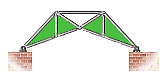
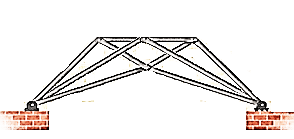
Complex Truss: A complex truss uses a general layout of members different from that used in simple and compound trusses. It often incorporates overlapping members.
Determination of nature and magnitude of a force in a member
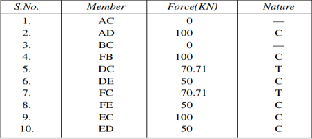
We can easily understand by assuming the magnitude and nature of forces in the various members of the truss shown in figure.
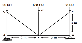
For Equilibrium
∑H = 0;
RBH = 0
∑V = 0;
RAV + RBV = 200
∑MB = 0;
RAV X 6 – 50 X 6 – 100 X 3 = 0
RAV = 100 KN And RBV = 100KN
Consider joint A;
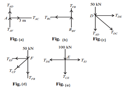
∑H = 0;
TAC = 0
∑V = 0;
RAV + TAD = 0
TAD = – 100 KN(C)
Consider joint B;
As shown in fig(b)
∑H = 0;
TBC = 0
∑V = 0;
RBV + TFB = 0
TFB = – 100 KN
Consider joint D;
As shown in fig(c) ∑V = 0;
– TAD – TDC sin 45 – 50 = 0
TDC = 70.71KN (T)
∑H = 0;
TDE + TDC cos 45 = 0
TDE = – 50KN (C) Consider joint F;
As shown in fig (d)
∑V = 0;
– TFB – TFC sin 45 – 50= 0
TFC = 70.71KN (T)
∑H = 0;
– TFE – TFC cos 45 = 0
TFE = – 50KN (C)
Consider joint E; as shown in fig(e)
∑V = 0;
– TEC – 100 = 0
TEC = – 100KN (C)
∑H = 0;
– TED + TEF = 0
TED = – 50KN (C)
Simple trusses zero force members.
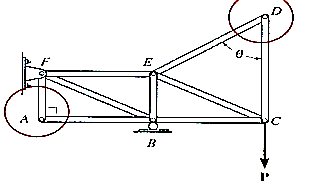
If a joint has only two non-collinear members and there is no external load or support reaction at that joint, then those two members are zero force members. In this example members DE, DC, AF, and AB are zero force members. Zero-force members can be removed (as shown in the figure) when analysing the truss.
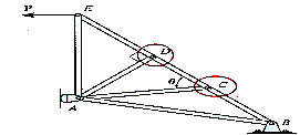
If three members form a truss joint for which two of the members are collinear and there is no external load or reaction at that joint, then the third non-collinear member is a zero-force member, e.g., DA
Again, this can easily be proven. One can also remove the zero-force member, as shown, on the left, for analyzing the truss further. Please note that zero-force members are used to increase stability and rigidity of the truss, and to provide support for various different loading conditions
Zero force members in a truss are members which do not have any force in them (obviously...). There are two rules that may be used to find zero-force members in a truss. These are described below and illustrated in Figure 3.3.
Case 1
At a TWO-member joint: If those members are NOT parallel AND there are no other external loads (or reactions) at the joint THEN both of those members are zero force members.
Case 2
In a THREE-member joint: If TWO of those members ARE parallel AND there are no other external loads (or reactions) at the joint THEN the member that is not parallel is a zero-force member.
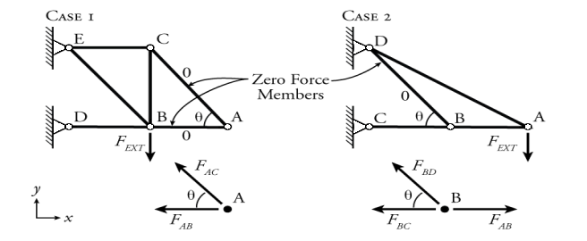
Fig. Examples of Zero Force Members
Two examples, one for each case, are shown in Figure 13. By applying equilibrium to the appropriate joints, we can see why the members shown do not have any force.
For the case 1 example, members AB and AC are zero force members. This may be shown to be the case by solving the equilibrium equations (1)(1) at joint A.

For vertical equilibrium (yy-direction), the vertical component of FAC is the only vertical force:
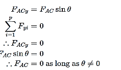
Therefore, FAC is a zero-force member. If we now apply horizontal equilibrium (xx-direction), we have two horizontal forces, FABFAB and the horizontal component of FAC:

Therefore, FAB must also be a zero-force member. In this example FACx and FAB are both negative because the arrows both point to the left. This analysis works for any two loads at joint which are not parallel where there is no external load on the joint.
For case 2 in Figure 3.3, member BD is a zero-force member. This may be shown to be the case by solving the equilibrium equations (1)(1) at joint B. For vertical equilibrium, the vertical component of FBDFBD is the only vertical force:
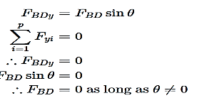
Therefore, FBD is a zero-force member. This analysis was simplified because the members BC and AB were parallel to the xx-axis; however, the orientation of the xx-axis is arbitrary, an analysis will show that member BD is a zero-force member as long as two of the members are parallel at the joint, even if they are not parallel to the xx- or yy-axis (try it out!). Finding these zero force members up front can save analysis time and effort.
Key takeaway:
1. Trusses are simply defined as triangulation of members to make the stabilized structure.
2. Triangular is the stable configuration mathematically. Generally, a truss has the members called as top chord, bottom chord, vertical chord and diagonal chord.
3. Truss members will carry only the axial forces
4. The nodes i.e. the connections of the members are designed as pinned joints so that moments won’t be transferred to the members of the truss
Willot Mohr's diagram:
Though no try is made hereto broaden or show the Williot-Mohr technique for figuring out truss deflections, the subsequent graphical system is defined as a foundation for the improvement of the analytic system.
The Williot diagram, that is drawn first, offers the moves of all joints of the truss with recognize to one of the joints and a member that enters that joint.
If the member that become used as a path reference honestly rotates with the deformation of the truss, the Mohr correction diagram ought to be brought to offer the genuine absolute moves of all the joints. The scaling of the Mohr correction diagram relies upon on the quantity that the authentic reference member honestly rotates, and the site of the correction diagram relies upon at the real motion of the authentic reference joint.
If a truss joint this is honestly constant towards translation is used because the reference factor for the Williot diagram, then each the Williot diagram deflection and the Mohr diagram correction for that joint might be zero.
A 2d factor at the Williot diagram can be placed with the aid of using the use of one of the contributors getting into the constant joint as a path reference.
A vector same to the deformation of that member is drawn from the reference factor i n the path in which the other joint of that member moves with recognize to the constant joint.
The location of the primary factors at the Williot diagram is proven in Figure 1. Point F"" at the Williot diagram corresponds to the constant joint F''' at the truss diagram.
The member connecting joints F ^ and is used as a path reference for the pWHW Williot diagram.
The vector r ' n - represents the value and path of the motion of joint H with recognize to joint F^, and thereby the placement of pomt at the Williot diagram is established.
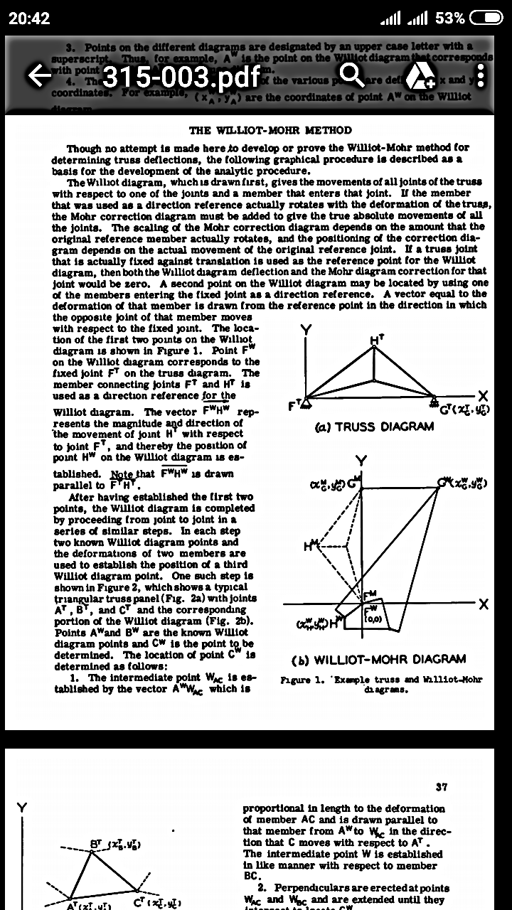
Note_that is drawn parallel to F^H^. After having mounted the primary factors, the Williot diagram is completed with the aid of using intending from joint to joint in a collection of comparable steps. In every step recognized Williot diagram factors and the deformations of contributors are used to set up the placement of a williot diagram factor. One such step is proven in Figure, which suggests a typical triangular truss panel (Fig.) with joints, B", and the corresponding part of the Williot diagram (Fig.). Points A^ and are the recognized Williot diagram factors and Cw is the factor to be decided. The vicinity of factor is decided as follows:
1. The intermediate factor W^^ is established with the aid of using the vector A'^Wy^c that is Proportional in lei^t h to the deformation of member AC and is drawn parallel to that member from A * to withinside the direction that C movements with admire to A^. The intermediate factor W is set up in like way with admire to member BC
2. Perpendiculars are erected at points W; ^c ^ ^B C ^ prolonged till they intersect to locate. This process is repeated till a coresponding Williot diagram factor has been set up for every joint of the truss. With the Williot diagram completed, the Mohr correction diagram may be drawn to present the genuine absolute moves of all the joints.
Because the constant joint of the truss turned into used because the place to begin for the Williot diagram, the correction in volves simplest the rotation of the structure approximately that joint till the guided joint is delivered again into its predetermined path.
The Mohr diagram is geometrically similar to the truss configuration, and furthermore, the traces of the Mohr diagram are perpendicular to the corresponding traces of the truss diagram.
Key takeaway:
1. The Williot diagram, that is drawn first, offers the moves of all joints of the truss with recognize to one of the joints and a member that enters that joint.
2. If the member that become used as a path reference honestly rotates with the deformation of the truss, the Mohr correction diagram ought to be brought to offer the genuine absolute moves of all the joints.
3. The Mohr diagram is geometrically similar to the truss configuration, and furthermore, the traces of the Mohr diagram are perpendicular to the corresponding traces of the truss diagram.
The simplest space truss configuration is a tetrahedron as shown in Fig. For an internally just-rigid configuration, there have to be four joints (-4) and six bars (m= 6).
For the truss to be externally stable and just-rigid, there have to be six components of support reactions, that are neither all parallel nor concurrent (r-6). An example of this is shown in Fig.
Thus, the condition for stable and statically determinate configuration is m+r 3). As in the case of simple plane truss it is possible to reduce the number of members and to compensate for the loss in internal rigidity by providing additional support reactions.
Additional members can now be introduced on the simple basic configuration by providing three additional members for every additional joint and connecting these members to the existing joints. The condition m+ 3j must be preserved to retain the just-rigid nature of the space truss.
If m+r exceeds 3j, then truss is likely to be over-rigid and hence statically indeterminate.
On the other hand, if m+r<3j, implying that there are not enough members for internal stability or enough support reactions for external stability, we clearly have a case of under-rigid or unstable truss.
As in the case of simple truss, it may be noted that the condition m+r=3j is only a necessary condition and not a sufficient one to ensure that the truss is stable and determinate.
It is also possible, as in the case of the plane truss, that the space truss satisfying the condition m+r-3j, happens to have a critical form. This can be detected by applying the zero-load test.
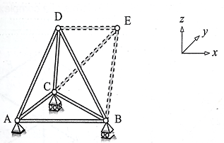
The hinged support at A arrests three orthogonal translations, while the hinged-roller at B arrests translations only in the y and directions, and the roller support at C arrests translation only in the vertical (2) direction. The six possible reaction components in this case are RAx RAy RAz RBx RBy and RBz
Key takeaway:
1. The simplest space truss configuration is a tetrahedron as shown in Fig. For an internally just-rigid configuration, there have to be four joints (-4) and six bars (m= 6).
2. For the truss to be externally stable and just-rigid, there have to be six components of support reactions, that are neither all parallel nor concurrent (r-6).
3. If m+r exceeds 3j, then truss is likely to be over-rigid and hence statically indeterminate.
References:
1. Theory and Problems in Structural Analysis by L Negi, Mc Graw Hill
2. Structural Analysis by T.S. Thandamoorthy, Oxford University Press
3. Basic Structural Analysis by C S Reddy, McGraw Hill
4. Elementary Structural Analysis by Norris and Wilber, McGraw Hill
5. Structural Analysis by Aslam Kassimali, Cengage Learin
6. Analysis by R.C. Hibbeler, Pearson Education