Unit - 5
Analysis of three hinged arches
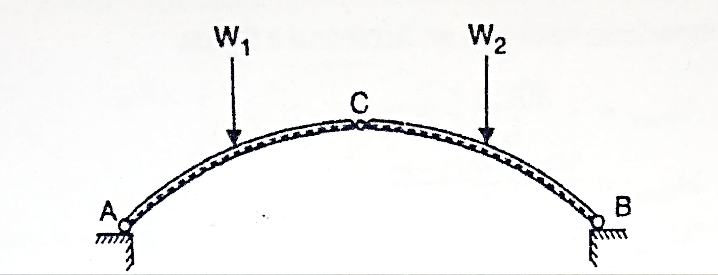
A three hinged arch is a statically determinate structure, having a hinge at each abutment or springing and also at the crown.
There are in all four reaction components (two at each hinge i.e., H and V). Three equations are available from the static equilibrium and one additional equation is available from the fact that the B.M. at the hinge at the crown is zero. Thus, the value of H can easily be calculated for any given load system.
Components of arch is shown in Fig.
A section of arch is subjected to three straining actions under the action of loads, these are
(1) Bending moment (M).
(ii) Normal thrust (N).
(in) Radial shear (F).
The B.M. is calculated using Eddy's theorem which is stated as, "The B.M. at any section of an arch is equal to the vertical intercept between the linear arch and the centreline of the actual arch."
B.M. at any section= Sum of moment due to loads Vertical reactions
(R), and Horizontal Thrust (H).
= Beam moment + H. moment
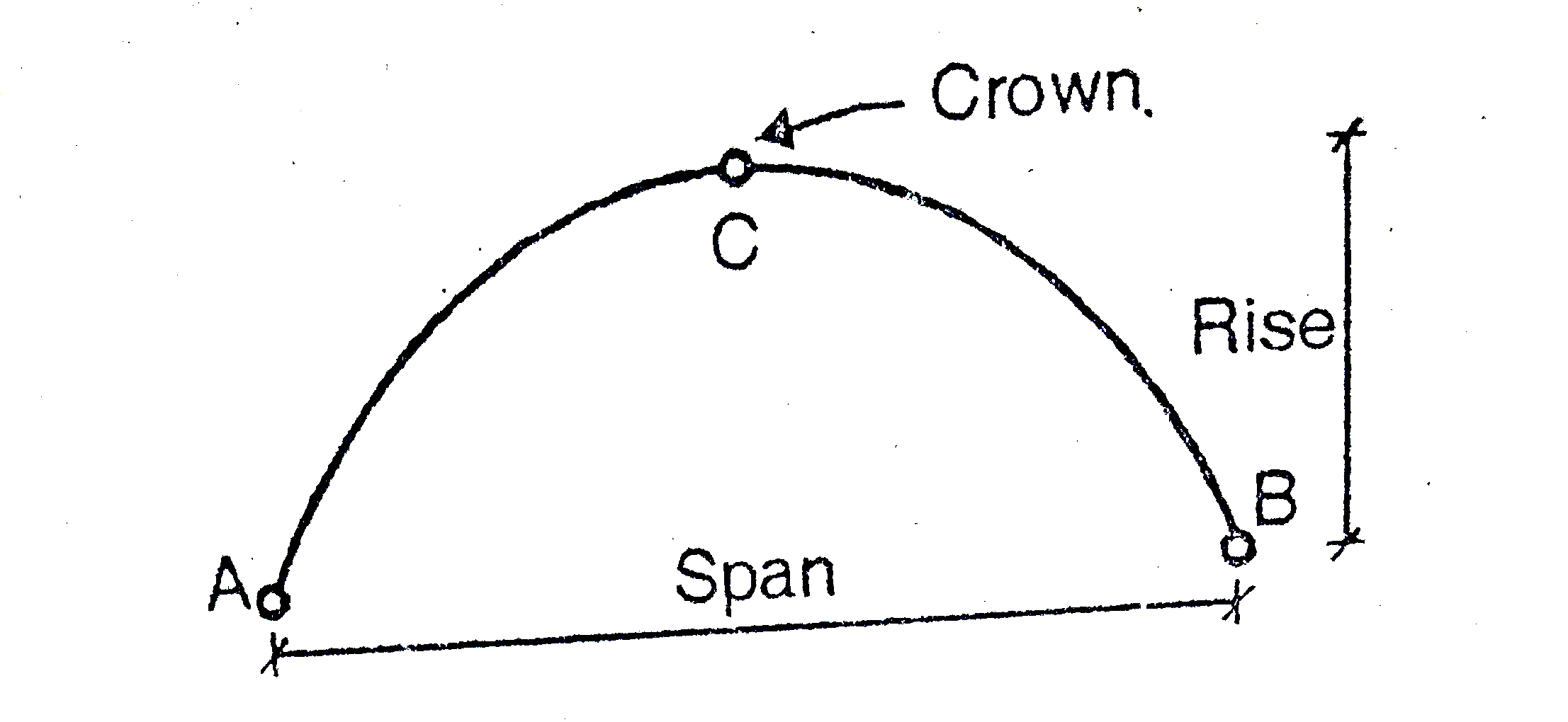
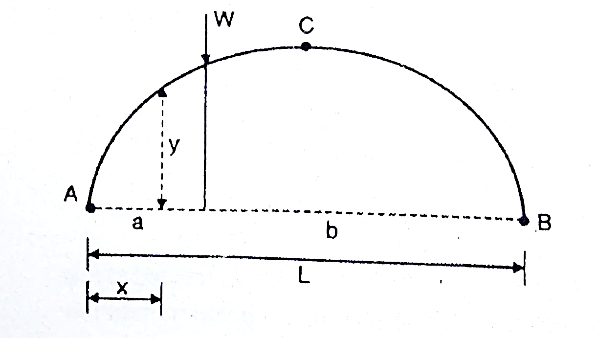
A three hinged arch consists of Two parts AC and BC hinged at C and supports A and B are two external hinges (Like an abutment).
1. Span of an arch: The horizontal distance between Two lower hinge supports A and B is known as span of arch
2. Rise of the arch: When supports A and B are at the same levels, the height of crown (C) is called rise of the arch. If the shape of the arch is parabolic then it is called parabolic
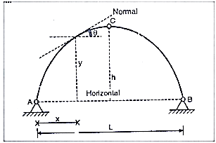
Equation type: 


C=
Equation of parabola is:
Y=
1. Bending moment diagram for three hinged arches:
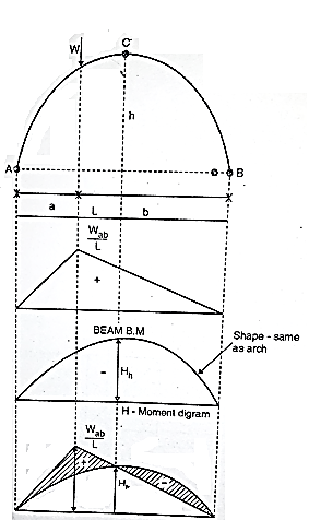
We know that for an arch, bending moment at any point is equal to beam BM-Hy (Refer comparison between arch and beam). Hy is called H-Moment. It varies with respect to Y. Therefore, the shape of BM due to Hy should be the shape of the arch. Therefore, to draw the BMD for an arch, draw the BMD for the beam over that superimpose the H-moment
Diagram as shown in Fig.
2. Steps of analysis of three hinged arch:
Step 1) Find reaction components
Draw F.B.D of arch taking two reaction components at each support and apply
Step 2) Find normal thrust and radial shear at any section.
Step 3) Find B.M. at any section
use Mx= Beam moment - H moment
Key takeaway:
Step 1) Find reaction components
Step 2) Find normal thrust and radial shear at any section
Step 3) Find B.M at any section
Cables are structural elements that resist loads by developing axial tension. They may form the primary load resisting structural component, as in the case of suspension bridges, cable stayed bridges, suspended roof systems, cable car systems, etc. In such cases, the main loads on the cables are usually gravity loads (either concentrated or distributed) transmitted from the suspended system (deck slab, roof or trolley). Compared to these heavy loads, the self-weight of the cable is usually negligible, and hence is generally ignored in the force analysis. In other applications, the cables may form a secondary support system, as in guyed towers, transmission line towers and derricks. In these cases, the cables do not support loads along their length, except for their self-weight and wind/snow loads acting on them.
The main cables (thick wire ropes) pass over the top of the pylons and are anchored to strong supports in the ground. The connection between the cable and the pylon may be either in the form of pulley support or saddle support.
In the case of the pulley support, the tension in the cable on either side is more or-less equal in order to satisfy force equilibrium, the resultant force in the cable support system, having both vertical and horizontal components, gets transmitted to the supporting pylon, using either a pulley arrangement or a saddle support.
In the pulley arrangement, the horizontal component of the main cable tension acting at the top of the pylon can result in a large bending moment at the base of the pylon, which acts like a vertical cantilever, and needs to be suitably designed for this purpose. This bending action on account of differences in the horizontal component of cable tension on either side of the pylon, gets practically eliminated in the saddle (roller) support arrangement which is shown in fig.
This requires the tension in the anchored portion of the cable not to be equal to the cable tension on the other side, the value being determined by horizontal force equilibrium.
With such a profile, the stiffening girder transmits practically no dead load to the al supports, as the load (including the self-weight of the stiffening girders) is carried by the espenders to the overhead cables.
However, under the action of moving live loads, the transmission of internal forces gets complicated. In order to ensure that the overall cable profile does not change with every passing vehicular load, and that it consistently remains parabolic, it is important to achieve a high degree of vertical stiffness in the so-called stiffening girders. The high stiffness in these girders helps to retain their straight profile, and thus also the parabolic cable profile, thereby ensuring that the forces in the suspenders are more-or-less equal, even under the action of concentrated live loads that may be eccentrically located.
ILD:
The loads acting on structures are broadly classified as dead loads or self weight and live loads or superimposed loads. Dead loads are those which do not change their position but live loads which can change their position during the life of the structures. When the structure subjected to moving type of load, the reactions at supports, shear force, bending moment and deflections vary with varying position of load system.
The graphical representation of such variation is called as influence line or 'influence line diagram' (ILD). The designer analyses the structures by drawing such type of graph to get critical position of loads.
Thus, the influence line diagram (ILD) may also be defined as a graph of stress resultants like a reaction at supports, shear force at a section, bending moment at a section for various positions of a unit load on the span of structure.
ILD are linear for determinate structures whereas curvilinear for indeterminate structures.
Uses of ILD
1. To determine reaction at supports for a given system of loads.
2. To determine the position of load for the maximum reaction.
3. To determine shear force and B.M at any section for the given system of loading.
4. To determine the position of loads for maximum S.F and B.M at a section.
ILD for the B.M:
Consider a beam AB is simply supported at the end.
Let C be the point or section for which we have to draw ILD for B.M
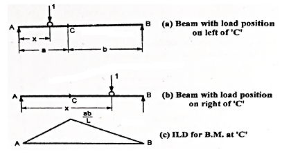
a. When unit load is at a distance x from A i.e., in between A to C. The moment at C is given by
Mc = RB x b
Since, RB = x/L
Mc = (x/L) x b
This equation is applicable for the portion AC for any position of unit load
At x= 0 Mc = 0
At x = a. Mc = ab/L
Therefore, the B.M varies from zero to A to ab/L at C
b. When unit load at a distance x from A i.e., in between C to B then,
Mc= RA x a
Since, RA = (L-x/L)
RA = (L-x)/ L X a
This equation is applicable for any position of unit load in portion CB
At x = a. Mc = (L-a/L) x a = ba/L
At x = L. Mc = 0
Therefore, BM diagram varies from ab/L at C to zero at B.
Example:
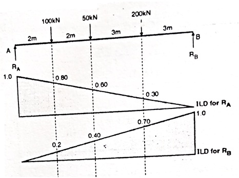
For the simply supported loaded as shown in fig. Draw (1) ILD for RA (2) ILD for RB. Determine the magnitude of RA and RB
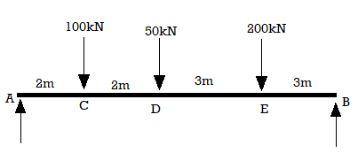
Solution:
1. ILD for RA
Join 1 and 0 by straight line and the resulting diagram will be
ILD for RA
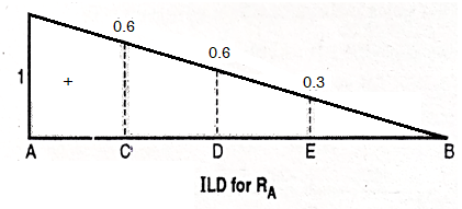
Originate at E = 1/10 X 3 = 0.3
At D = 0.6 and at C = 0.8
2. ILD for RB
Join 0 and 1 by straight line and the resulting diagram will be ILD for RB
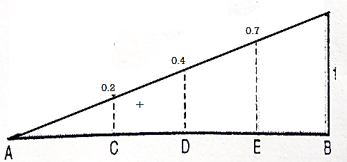
Originate at C = 1/10 X 2 = 0.2
At D = 0.4
At E = 0.7
3. Magnitude of RA and RB
RA = magnitude of load X corresponding ordinates on ILD
RA = 100 X 0.8 + 50 X 0.60 + 200 X 0.3
RA = 170 KN
Similarly
RB = 100 X 2 + 50 X 0.4 + 200 X 0.70
RB = 180 KN
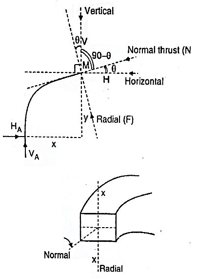
At any section X-X of arch the total force acting along the normal is called normal thrust and total force acting along the radial direction is called radial shear. For the case shown in fig.
To determine normal thrust and radial shear at any point cut the arch into 2 parts. Consider any 1 part. Determine net horizontal (H) and vertical (V) force on to the section. Using these forces calculate normal thrust and radial shear.
Components of two forces V and H along normal direction.
We get,
Normal thrust N =+H
N =H
Treat the normal thrust as + ve if it is acting towards the arch and - ve if it is away from the arch.
Composition of two forces V and H along radial direction
We get,
Radial shear F = +V 
F = V 
Treat force up the radial direction+ ve and down the radial direction as - ve.
References:
1. Theory and Problems in Structural Analysis by L Negi, Mc Graw Hill
2. Structural Analysis by T.S. Thandamoorthy, Oxford University Press
3. Basic Structural Analysis by C S Reddy, McGraw Hill
4. Elementary Structural Analysis by Norris and Wilber, McGraw Hill
5. Structural Analysis by Aslam Kassimali, Cengage Learin
6. Analysis by R.C. Hibbeler, Pearson Education