Unit - 2
Soil Hydraulics
- Water present in voids of soil mass is called soil water.
- Soil water can be classified in many ways.
- Classification of soil water:
1. Broad classification:
- Free water
- Held water
2. Phenomenological basis:
- Ground water
- Capillary water
- Absorbed water
- Infiltered water
3. Structural aspect:
- Pore water
- Solvate water
- Absorbed water
- Structural water
Key Takeaways:
Soil water is classified inti three types: Broad classification, Phenomenological basis, Structural aspect.
- Consider a rigid cylindrical mould or container as shown in Fig. The dry sand is filled in this rigid cylindrical mould. It is assumed that there is no side friction in the cylindrical container or mould.
- Surface of the soil is subjected to load Q through a piston and this load is transferred to the dry soil grains filled in the container through their points of contact. The average stress at any section x-x can be determined as follows
 av =
av =
Where,  av =Average stress; A= sectional area of the cylinder
Any plane like x-x do not pass through all the points of contact, but many of the grains are cut by the plane x-x and the actual points of contacts seems like a wavy form.
The average stress which is responsible for the deformation of the soil mass is called as effective stress or intergranular stress see Fig. For better understanding. Note that o, o is the effective stress.
- In another experiment, cylindrical mould is filled with the fully saturated soil and cylindrical mould is entirely made water tight. If the same load (Q) is placed on the piston, the load will not be transmitted to the soil grains but in case of Fig. The same load was transmitted to the soil grains (dry).
- Pore Pressure: The pressure which is developed in the water due to external load transmitted to the water in the pore by assuming water to be incompressible is called as pore pressure or neutral stress (uw) which is shown in Fig.
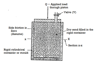
Fig 1: Specimen
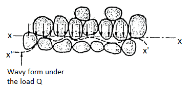
Fig 2: Intergranular pressure
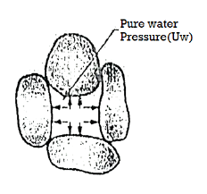
Fig 3: Pore water pressure
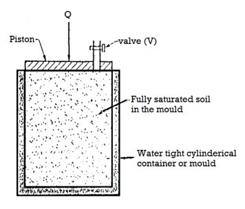
Fig 4: The effective stress principle
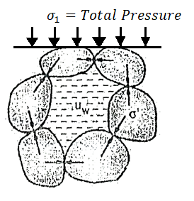
Fig 5: The effective stress principle
uw = neutral stress=Q/A
Where, Q=load applied by piston
A=sectional area of the cylinder
Uw =pore pressure or neutral stress
- In Fig., as soon as valve V is opened, there will be immediately, expulsion of water through the hole and this flow continues for some time and then stops. Note that expulsion of water from the pores decreases the pore water pressure, but increases the intergranular pressure. Hence at any stage; the total pressure split up between water and the points of contact of grains which make a new equation as follows:
Total pressure ( ) =
) =  + uw
+ uw
Where,  =Intergranular pressure
Uw =pore water pressure or neutral stress.
For no expulsion of water, uw = 0,
Hence total pressure ( )= Intergranular pressure (
 )
)
Fig. Shows the concept of total pressure, intergranular pressure and pore water pressure.
 =
= is called as effective stress equation where
  =effective stress,
  t=total pressure and uw= porewater pressure.
Key Takeaways:
The pressure which is developed in the water due to external load transmitted to the water in the pore by assuming water to be incompressible is called as pore pressure or neutral stress.
- Definition: Permeability is defined as "The property of a porous material which permits the passage or seepage of water (or other fluids) through its interconnecting voids".
- If water flow easily through voids of soil, then soil is highly pervious or permeable and when the permeability is extremely low it is called impervious or impermeable.
Coefficient of Permeability:
- Definition: The coefficient of permeability (K) is "The average velocity of flow that will occur through the total cross-sectional area of soil under unit hydraulic gradient" and unit is cm/sec, m/day, feet/day
- According to USBR soil having the coefficient of permeability greater than 10 mm/sec such soils are permeable soils.
- Soils having values less than 10 mm/sec are impermeable soils.
- The soils which have in between values are semi-permeable soils.
Key Takeaways:
Permeability is defined as "The property of a porous material which permits the passage or seepage of water (or other fluids) through its interconnecting voids".
Factors affecting permeability:
Permeability depends on many factors. Following are the main factors that affect permeability:
Grain size:
- Grain size of the soil, or the effective size Dio is one of the factors which affect permeability. Allen Hazen gave the relation.
K = C(D10)2
Where, K Coefficient of permeability in cm/s and D10 is the effective grain size of the soil, C= constant (between 100 to 150)
- The permeability of coarse-grained soil is more than that of fine-grained soil
Properties of pore fluid:
- Permeability is directly proportional to the unit weight of pore fluid and inversely proportional to the viscosity of the pore fluid.
Temperature:
- Since viscosity of the pore fluid decreases with the temperature, permeability increases with temperature, as unit weight of the pore fluid does not change much with change in temperature.
Void ratio:
- Increase in void ratio increases the area available for flow, hence the permeability increases for critical conditions.
K e2
e2
Stratification of soil:
- Stratified soils are those, which are formed by layer upon layer of earth or dust deposited upon one another.
- If the flow is parallel to the layers or stratification, the permeability is maximum while the flow in perpendicular direction to the stratification occurs with minimum permeability.
Entrapped air and organic impurities:
- Organic impurities and entrapped air obstruct the flow and coefficient of permeability is reduced due to their presence.
Adsorbed water:
- Adsorbed water means a thin, microscopic film of water surrounding individual soil grains.
- This water is not free to move and hence reduces the effective pore space and thus decreases the coefficient of permeability.
Degree of saturation:
- The permeability of partially saturated soil is less than that of fully saturated soil.
Shape of particles:
- Permeability is inversely proportional to the specific surface e.g.; the angular particles have more specific surface as compare to rounded particles. Therefore, the soil having angular particles is less permeable than soil of rounded particles.
Structure of soil mass:
- For same void ratio the permeability is more for flocculant structure as compare dispended structure.
Key Takeaways:
Factors affecting permeability are as follows:
- Grain size
- Properties of pore fluid
- Temperature
- Void ratio
- Stratification of soil
- Entrapped air and organic impurities
- It states that in a steady, ideal flow of an incompressible fluid, the total energy at any point of the fluid is always constant.
∴Total Energy = constant
Pressure energy+ Kinetic every + Potential energy = Constant
∴ 
Where, = pressure energy or pressure head per unit weight
 kinetic energy or kinetic head per unit weight
- All practical fluids are viscous and offer resistance to fluid flow. So that there are some losses in fluid flow between two sections. Bernoulli's equation was derived on the assumption that fluid is non-viscous i.e., frictionless. Which is not applicable of practical fluid and hence Bernoulli's equation is modified by considering losses.
- Modified Bernoulli's equation for real fluid.
Where hL = loss of energy between point 1 and 2.
Modified Bernoulli's equation in K.E. Correction factor ' ' considered
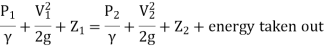
Modified B.E. If some energy is taken out from 1 to 2
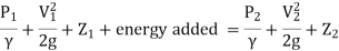
Modified B.E. If energy is added from 1 to 2.
Key Takeaways:
Bernoulli's equation is based on Euler's theory of fluid flow and it obtained by integrating the Euler's equation of motion.
- In 1856 Darcy studied and demonstrated experimentally, the velocity of laminar flow through homogeneous soil mass, which states that, "The rate of flow or the discharge per unit time is proportional to the hydraulic gradient."
q= K.i.A
V=q/A
V i, V=Ki
Where,
q= discharge per unit time
A= total c/s area of soil mass, perpendicular to the direction of flow
i =hydraulic gradient K Darcy's coefficient of permeability
v =velocity of flow, or average discharge velocity
- If a soil sample of length 1 and cross-sectional area A, is subjected differential head of water hA-hB, the hydraulic gradient i will be equal to (hA-hB)/L and
We have,
q=KA (hA-hB)/L
When hydraulic gradient i = 1, then k=v
Key Takeaways:
Darcy’s law states that, "The rate of flow or the discharge per unit time is proportional to the hydraulic gradient."
- Hydraulic Conductivity is the ability of porous medium (i.e., Soil) to transmit water under saturated or nearly saturated conditions.
i =K
Where, i = water flux
K =hydraulic conductivity
 gradient head
- Hydraulic Conductivity (K) is a crucial hydraulic parameter because it influences the surroundings via way of means of controlling infiltration, irrigation rate, and therefore the water motion via the ground.
- In order to decide Hydraulic Conductivity in a soil column all through unsaturated flow, experiments had been done withinside the laboratory.
- A sandy (S) soil pattern of regarded Hydraulic Conductivity at saturation (KS) changed into located uniformly in an obvious column. Using a pump, water changed into implemented on the floor of the soil column in sure supplies (Qi), even as soil moisture (θ) changed into measured the use of TDR probes.
- At the identical time, soil pore stress (h) changed into measured the use of stress transducers. The cumulative quantity of the outgoing water (V) of the column changed into measured.
- Experimental facts had been outfitted via way of means of Van Genuhten's Hydraulic Conductivity model. The effects of the above experimental technique represent beneficial gear for the simulation of water motion in unsaturated soils and may be the outset for similarly research.
- Hydraulic conductivity is depending on elements along with soil texture, particle length distribution, roughness, tortuosity, shape, and diploma of interconnection of water-engaging in pores.
- If we had been best deliberating soil texture, coarser textured soils could generally have better hydraulic conductivities than fine-textured soils. However, soil shape and pore shape may have a huge effect on a soil’s cap potential to transmit water.
- A based soil generally incorporates massive pores, whilst structureless soils have smaller pores. It shows the distinction among a nicely based clayey soil and a poorly based clayey soil and the significance of shape to hydraulic conductivity, mainly at or close to saturation.
- Biopores, root channels, or animal burrows growth saturated hydraulic conductivity in the event that they incorporate water. If they don’t fill with water due to the fact, they don’t attain the surface, they could lower conductivity. Compaction or the density of the soil is some other influencing factor, in addition to the water content material or the water cap potential of the soil.
- Stratified soils are those, which are formed by lager upon lager of earth or dust deposited upon one another.
- If the flow is parallel to the lagers or stratification, the permeability is maximum while the flow is perpendicular direction to the stratification occurs with minimum permeability shown fig.
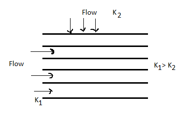
Fig 6: Horizontal strata
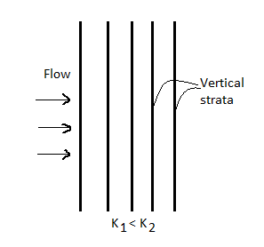
Fig 7: Vertical strata
(1) Average permeability parallel to the bedding planes
- Let L1, L2…Ln be thickness of layer.
- K1, K2…Kn be permeability of layer.
- For flow to be parallel to the bedding planes, the hydraulic gradient i will be the same for all the layers.
- However, since V Ki and K is different, the velocity of flow will different in different layers.
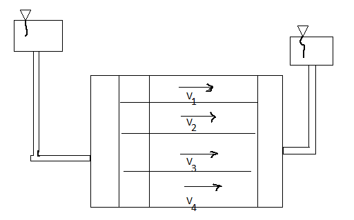
Fig 8: Flow parallel to bedding plane
- Let K= average permeability of the soil deposit parallel to the bedding plane.
- Total discharge through the soil deposit sum of discharge through the individual layers.
q=q1, q2…. Qn
Kx = 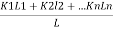
(2) Average permeability perpendicular to the bedding planes
- In this case, the velocity of flow and hence the unit discharge, will be the same through each layer. However, the hydraulic gradient and hence loss through each lager will be different. Denoting the head loss through the lagers by h1,h2….hn, and the total head loss as h we have
h=h1+h2+...hn
But h1=iL1 h2=iL2
h=iL1+iL2+iL3+…
Now, if KZ=average permeability perpendicular to the bedding plane.
We get,
Kz=
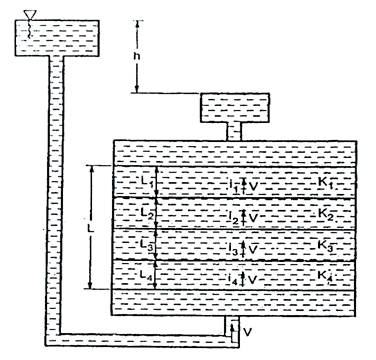
Fig 9: Flow perpendicular to bedding plane
- Hence for same void ratio, the soil with rounded particles are more permeable than with angular particles.
Key Takeaways:
Stratified soils are those, which are formed by lager upon lager of earth or dust deposited upon one another. If the flow is parallel to the lagers or stratification, the permeability is maximum while the flow is perpendicular direction to the stratification occurs with minimum permeability.
- There is an energy transfer between the water and the soil due to the viscous friction exerted on water flowing through the soil pores.
- The pressure exerted by water on the soil through which it percolates is known as seepage pressure (Ps).
It is given by,
Ps=h
Ps =  ×L
×L
Where, h=Hydraulic head,
Z= Length over which the head (h) is lost,
i = Hydraulic gradient,
 =Unit weight of water
Seepage force (F) is given by,
Fs= Ps. A= i.Z. A
A
Where A= Total cross-sectional area of the soil mass
 =Unit weight of water
The seepage pressure always acts in the direction of the flow.
The effective pressure (P) in the soil mass is given by
Pe=Z ± iz
± iz
For upward flow,
Pe=Z - iz
- iz
In upward direction, the effective pressure is decreased hence-ve sign.
For downward flow,
Pe=Z +iz
+iz
In downward direction, the effective pressure is increased hence +ve sign.
Key Takeaways:
The pressure exerted by water on the soil through which it percolates is known as seepage pressure.
- The quantity of water flowing through a saturated soil mass and the distribution of water pressure can be estimated by the theory of flow fluids through porous medium.
- Flows out in the same length of time.
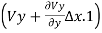
- Consider an element of soil of size
 x,
x,  y and of unit thickness perpendicular to the plane of the paper.
 - Let Vx, and Vy, be the entry velocity components in x and y direction, av,
- Then
 and
and  will be the corresponding velocity components at the exit of the element.
 - According to assumption 3 stated above, the quantity of water entering the element is equal to the quantity of water leaving it.
 (
( )+
)+ (
( )=
)= (
( +
+
From which +
+ =0
=0
According to assumption 1.
While computing these quantities with the help of theoretical analysis following assumptions are made.
- Darcy's law for flow through porous medium is valid.
- Soil and water are incompressible.
- Soil is isotropic and homogeneous.
- The soil is fully saturated.
- The flow is steady.
- The flow is two-dimensional.
- There is no change in the degree of saturation in the zone of soil through which water seeps.
Fig 10: Two-dimensional flow
The quantity of water flowing into any element of volume is equal to the quantity which the quantity of water entering the element is equal to the quantity of water leveling it.
 (
( )+
)+ (
( )=
)= (
( +
+
From which +
+ =0 …..(1)
According to assumption 1,
Vx= Kx.ix =Kx
Vy= Ky.iy =Ky
Where, h =Hydraulic head under which water flows.
Kx and Ky= Coefficients of permeability in x and y direction.
Substituting these in Equation (i)
 +
+ =0
=0
We get,
 +
+ =0
=0
For an isotropic soil, Kx=Ky=K(say)
∴ +
+ =0
=0
Substituting  Kh =Velocity potential in Equation, we get
 +
+ =0
=0
This is the Laplace equation of flow in two dimensions.
- When water flows through Soil in laminar flow conditions, the paths along which the layers of water flow are called flow lines.
- Equipotential lines are the lines joining points of equal pressure along the flow lines. These can also be defined as lines along which the points have equal head of water.
- If piezometers or glass tubes are inserted along an equipotential line, water will rise to the same height in the tubes.
- Equipotential lines are always perpendicular to the flow lines.
- Analysis of seepage phenomenon is simplified by using the graphical solutions. One of the most use graphical tool is "Flow Net".
- The grid, mesh or net formed by the intersection of equipotential lines and flow lines is called flow-net.
- The portion of a flow net between two adjacent flow lines is called a low channel.
- Every section of a flow channel between two successive equipotential line is called a field.
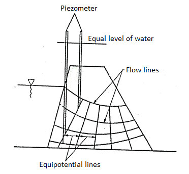
Fig 11: Flow lines and equipotential line
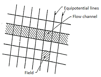
Fig 12: Flow net
Properties of Flow net:
- Following are the characteristic of flow-net, which are useful in construction of flow-nets and in calculation in solving seepage problems:
- In a flow-net, flow lines and equipotential lines intersect each other at right angles.
- The quantity of water flowing through each flow channel is the same.
- The drop of head or potential drop between any two successive equipotential lines is the same.
- The fields are approximately squares.
- The flow net is representative of the flow pattern and dissipation of the hydraulic head see fig below.
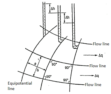
Fig 13: Part of flow net illustrating characteristics
Application of Flow net:
- A flow net chart is used for following purposes:
- Determination of discharge.
- Determination of total head.
- Determination of pressure head.
- Determination of hydraulic gradient.
- For calculating quantity of seepage.
- For stability of earthen dam.
- For analysis of flow phenomenon.
- For stability analysis.
Key Takeaways:
The grid, mesh or net formed by the intersection of equipotential lines and flow lines is called flow-net.
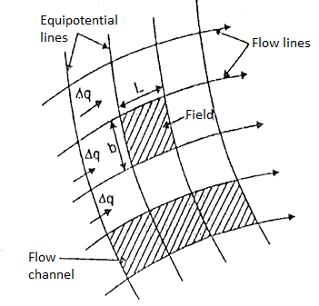
Fig 14: Portion of flow net showing field and flow channels
The portion between two successive flow lines and successive equipotential lines is termed as field.
Let: L= Length of field and b= width of field
 h =Head drop through the field
 q= Discharge through the flow channel
H=Difference between w/s and D/s heads
From Darcy's law of flow through soils, we know,
 q = K.i.A
Consider the unit thickness of the field,
For square field, L=b, we get,
∴ …(1)
…(1)
Let H =Total head loss =h1-h2

Where, Nd= Number of equipotential drops
Substituting in Equation (1), we get,
∴ …(i.e., discharge through one channel)
The total discharge through the complete flow net is given as,
q =
Where, Nf = Number of flow channels
=
∴q =K×H× …(2)
…(2)
Equation (2) gives the seepage discharge.
 is called as shape factor of the flow net.
- ABC is a sheet pile driven in pervious layer of depth d, the depth of embedment BC being d' Fig.
- UB and TV are potential boundaries with known heads. BCST and xy are flow line boundaries because these are impervious surface across which water cannot pass.
- Flow lines will emerge at right angles from UB and end at right angles at TV. Because of symmetry flow not will symmetrical, about vertical axis.
Procedural steps:
- Make a scale drawing showing the structure, soil mass, the pervious boundaries and the impervious boundaries.
- Sketch the first trial flow line as f1 f1 Emerging at right angles at UB running round the sheet pile and meeting TV at right angles.
- Sketch the first equipotential line p1 p1so as to make a square figure with the flow line f1 f1 and the boundary BC and ending at right angles to the boundary flow line, Now sketches the second flow line f2 f2 again emerging at right angles with UB making square figure with P, P, going round the sheet pile parallel to the first line f1 f1 and ending at right angles to TV.
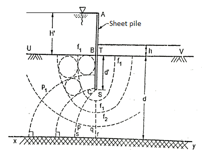
Fig 15: Flow net for sheet pile
4. Then sketch the next trial potential line, emerging at right angles from BC, making square figures with neighboring flow lines and meeting xy at a right angle. Continue sketching to complete the flow net.
5. Now, check (by drawing circles touching all the sides of the square) the square figures and orthogonality everywhere in the flow net. The first attempt can hardly produce a good flow net. Make a second, third and if required more attempts, till a reasonably good flow net has been sketched.
Figure shows the dam section ABCD has FC as blanket filter and ENJ as top seepage line. BC represents rock line.
Steps:
- Boundaries: EB and FC are potential boundaries and ENJ and BF are bound flow lines.
- Sketch the first trial flow line f1f1 that emerges from EB at right angles, runs keeping the distance from top seepage line and ends at filter boundary at right angle.
- Sketch equipotential lines P₁ P₁ P2 P2. Etc. so that they emerge and meet the boundary flow lines at right angles and form square figures.
- Check the orthogonality and square figures in the figure Pqrs is a non-square if many figures are found to be "non-square" adjust the trial flow line and sketch new equipotential lines. There or more such trial will yield reasonably good net.
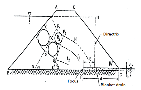
Fig 16: Flow net for earthen dam
- When flow takes place in an upward direction, the effective pressure gets reduced since the seepage pressure also acts in the upward direction.
- When the seepage pressure becomes exactly equal to the submerged weight of the soil, through which the flow is taking place, the effective pressure becomes zero.
- In this case, the soil with less cohesion loses all its shear strength and soil particles move up in the direction of flow. This lifting of soil particles is known as quick sand condition or boiling sand condition during this condition the effective pressure reduces to zero.
i= ic =
- The hydraulic gradient of the quick sand condition is known as the critical hydraulic Gradient(ic).
- Thus, quick sand condition is the particular flow condition which occurs when effective pressure reduces to zero during upward flow.

Fig 17: Quick Sand Condition
Key Takeaways:
When the seepage pressure becomes exactly equal to the submerged weight of the soil, through which the flow is taking place, the effective pressure becomes zero. In this case, the soil with less cohesion loses all its shear strength and soil particles move up in the direction of flow. This lifting of soil particles is known as quick sand condition.
Numericals:
Q. The void ratio of a sand sample at the loosest and densest possible states are found to be 0.55 and 0.98 respectively. If G=2.67 determine the corresponding values of the critical hydraulic gradient?
Soln.:
Critical hydraulic gradient Ic=
Critical gradient for loosest state,
e =0.55
∴Ic =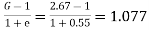
Critical gradient for densest state,
e =0.98
∴Ic =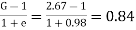
Q. A Cylindrical mould of diameter 7.5cm contains a 15cm long sample of line sand when water flows through the soil under constant head at a rate of 58cm/min the loss of head between two points 8 cm part is found to be 12.1cm. Determine the coefficient of permeability of the soil.
Soln:
A=
L=15cm
H=8cm
Q=q=58cm3/min
K=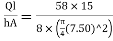
K=2.462cm/min
Q. Determine the coefficient of permeability of soil from the following data:
Length of soil sample=25cm
Area of c/s of the sample=30cm2
Head of water=40cm
Discharge=200ml in 110sec
Soln.:
K =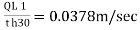
Q. What is the critical gradient of sand deposit of sp. Gravity=2.65 and porosity 35%.
Soln:
e =0.35
∴Ic=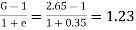
Q. In order to compute the seepage loss through the foundation of dam, flow net was drawn. The flow net study gave number of flows channel Nf=8 and number of equipotential drop Nd=18.The head of water lost during seepage was 6m if the coefficient of permeability of foundation soil is 4×10^-5 m/min. Compute the seepage loss per meter length of dam per day.
Given:
Number of flow channels Nf=8
Number of potential drops, Nd=18
Head loss=6m
K=4×10^-5 m/min
q =
L=1m
Q=qL=10.67×10^-5×60×24
∴Q=0.154 m3/day
Q. A sample in variable head parameter is 8cm in diameter and 10 cm high. The permeability of the sample is estimated to be 10×10^-4cm/sec. If it is desired that the head in the standpipe should fall from 24 cm to 12cm in 3 min, determine the size of the standpipe which should be used.
Given:
D=diameter of sample=8cm
K=Permeability of sample=10×10^-4cm/sec
Hl =24cm
HL =12cm
t =3minutes=180sec
L=Length of sample=10cm
a =cross sectional area of standpipe
To find the size of standpipe (i.e., d =diameter)
Let d be the diameter of standpipe to be determined
A=cross sectional area of sample=
∴A=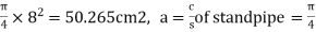 d^2
d^2
We know,
K=
10
d =4.079
∴d=4.08cm
References:
- Principles of Geotechnical Engineering by Braja M. Das, Cengage learning
- Soil Mechanics and Foundation Engineering by K.R. Arora, Standard Publishers
- Soil mechanics and Foundation Engineering by B.N.D. Narsingarao, Wiley India Pvt. Ltd.
- Basic and applied soil mechanics, by Gopal Ranjan, A.S.R Rao, New age International publishers


