Unit 3
Basic Power transmission devices
BELT DRIVES:
The belt drive is used to transmit power from one shaft to another by means of pulleys which rotate at the same speed or at different speed.
I) open and cross belt drive
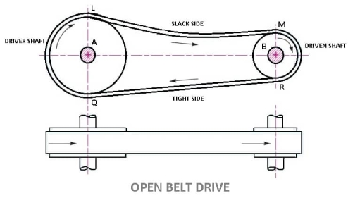
LENGTH OF OPEN BELT DRIVE FORMULA:
= π (r1 + r2) + 2x + (r1 – r2)2 /x ……………. (In terms of pulley radii)
= π/2 (d1 + d2) + 2x + (d1 – d2)2/ 4x ……….… (In terms of pulley diameters)
2. Cross Belt Drive
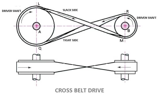
LENGTH OF CROSS BELT DRIVE
= π (r1+r2) + 2x + (r1+r2)2 /x …………… (In terms of pulley radii)
= π/2(d1+d2) +2x + (d1 + d2)2/ 4x …………(in terms of pulley diameters)
Material of belts:
The Materials used for belts and ropes must be strong, flexible, and durable. It must have high coefficient of friction: like
1- Leather belts
2- Cotton belts
3- Rubber belts
4- Balata belts
1. Leather belts :
The leather may be oak tanned or mineral salt tanned. Example chrome tanned. When the thickness of the belt required is more then, two or more strips are cemented together. Leather belts require periodic cleaning.
2. Cotton belts or Fabric belts :
Fabric belts are made by folding canvas or cotton ducks in layers and stitching together. The fabric belts are cheaper and best suited in warm climates, damp atmospheres. These are mostly used in Farm machinery, belt conveyor etc.
3. Rubber belts :
Rubber belts are made of Fabric with rubber layer. Rubber belts are used in sawmills, paper mills, etc.
4. Balata Belts:
Balata belts are similar to rubber belts except that balata gum is used in place of rubber. Balata belts are acid proof and water proof and it is not affected by animal oils or alkalis. The balata belts should not be at temperatures above 40° C because at this temperature the balata begins to soften and becomes sticky. The strength of balata belts is 25 percent higher than rubber belts.
Type of belts:
Different types of belt are as follows

1. Flat Belt :
Flat belt has a rectangular cross section. Flat belts are capable of transmitting power over long distance between pulley centres. The efficiency of this drive is around 98 % and produces less noise.
This belt is mostly used in factories and workshops, where a moderate amount of power is to be transmitted, from one pulley to another when two pulleys are not more than 8 metres apart.
Flat belts drives are of following types:
2. V – Belt:
V-Belts also used with grooved pulleys, V-belts are trapezoidal in cross section. V-belts permit large speed ratios and can transmit higher power. Multiple drives are possible.
This belt is mostly used in factories and workshops, where a moderate amount of power is to be transmitted, from one pulley to another when two pulleys are very near to each other.
3. Circular Belt or Round Belt :
Circular Belt or Round belt has a circular cross section and is used with grooved pulleys, This belt is mostly used in factories and workshops, where a great amount of power is to be transmitted, from one pulley to another when two pulleys are more than 8 metres apart.
Length of belt of open and cross drive:
Length of Open belts drive:
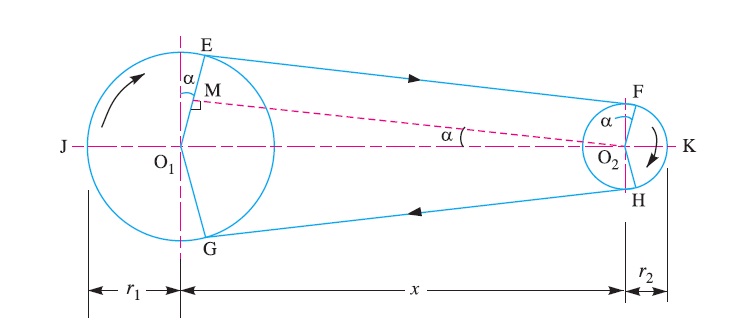
We have discussed that in an open belt drive, both the pulleys rotate in the same direction as shown in Fig. 1.
Let r1 and r2 = Radii of the larger and smaller pulleys,
x = Distance between the centres of two pulleys (i.e. O1O2), and
L = Total length of the belt.
Let the belt leaves the larger pulley at E and G and the smaller pulley at F and H as shown in Figure. Through O2 draw O2M parallel to FE.
From the geometry of the figure, we find that O2M will be perpendicular to O1E.
Let the angle MO2O1 = α radians.
We know that the length of the belt,
L = Arc GJE + EF + Arc FKH + HG
= 2 (Arc JE + EF + Arc FK) ……………………..(i)
From the geometry of the figure, we also find that
sin α = O1M/O1O2 = O1E – EM / O1O2 = r1 – r2 / x
Since the angle α is very small, therefore putting
sin α = α (in radians) = r1 – r2 / x …………………….(ii)
∴ Arc JE = r1 (π/2 + α) ………………………….(iii)
Similarly, arc FK = r2 (π/2 – α) ……………………..(iv)
and EF = MO2 = [(O1O2)2 – (O1M)2]0.5
= [x2 – (r1 – r2)2]0.5
= x [1 – {(r1-r2) /x }2 ]0.5
Expanding this equation by binomial theorem, we have
EF = x [1 – {0.5 {(r1 – r2)/x} + …] = x – (r1 – r2)2 /2x …………………..(v)
Substituting the values of arc JE from equation (iii), arc FK from equation (iv) and EF from equation (v) in equation (i), we get
L = 2 [r1(π/2 +α) + x – {(r1-r2)2/2x} + r2(π/2 -α)]
= 2 [{r1 × π/2} + {r1×α} + x – {(r1- r2)2/2x} + {r2 × π/2} - {r2×α}]
= 2 [π/2(r1+r2) + α(r1-r2) +x – {(r1-r2)2/2x}]
= π(r1+r2) + 2α(r1-r2) +2x – {(r1-r2)2/x}
Substituting the value of α = (r1-r2)/x from equation (ii), we get
L = π(r1+r2) + 2{(r1-r2)/x}{(r1-r2)} +2x – {(r1-r2)2/x}
= π(r1+r2) + 2{(r1-r2)2/x} + 2x – {(r1-r2)2/x}
= π (r1 + r2) + 2x + (r1 – r2 )2 /x ……………. (in terms of pulley radii)
= π/2 (d1 + d2) + 2x + (d1 – d2)2 /4x …… (in terms of pulley diameters)
Length of cross belt drive:
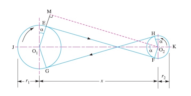
We have discussed that in a cross belt drive, both the pulleys rotate in the opposite directions as shown in Fig
Let r1 and r2 = Radii of the larger and smaller pulleys,
x = Distance between the centres of two pulleys (i.e. O1O2 ), and
L = Total length of the belt.
Let the belt leaves the larger pulley at E and G and the smaller pulley at F and H as shown in Figure.
Through O2 draw O2M parallel to FE.
From the geometry of the figure, we find that O2M will be perpendicular to O1E.
Let the angle MO2O1 = α radians.
We know that the length of the belt,
L = Arc GJE + EF + Arc FKH + HG
= 2 (Arc JE + FE + Arc FK) …………………(i)
From the geometry of the figure, we find that
sin α = O1M/O1O2 = (O1E + EM)/O1O2 = r1+r2 / x
Since the angle α is very small, therefore putting sin α = α (in radians = r1+r2 / x ………………………….…(ii)
Arc JE = r1 (π/2 + α) ………………. ……(iii)
Similarly, arc FK = r2 (π/2 + α) …………………(iv)
EF = MO2 = [(O1O2 )2 – (O1M)2]0.5
= [x2 – (r1 + r2 )2]o.5
= x [1- (r1+r2 /x )2 ]0.5
Expanding this equation by binomial theorem, we have
EF = x [1- 1/2(r1+r2 /x)2 + …] = x – [(r1+r2)2/2x] ……………………(v)
Substituting the values of arc JE from equation (iii), arc FK from equation (iv) and EF from equation (v) in equation (i), we get,
L = 2 [r1(π/2 +α) + x – {(r1+r2)2/2x} + r2(π/2 +α)]
= 2 [{r1 × π/2} + {r1×α} + x – {(r1+r2)2/2x} + {r2 × π/2} + {r1×α}]
= 2 [π/2(r1+r2) + α(r1+r2) +x – {(r1+r2)2/2x}]
= π(r1+r2) + 2α(r1+r2) +2x – {(r1+r2)2/x}
Substituting the value of α = (r1+r2)/x from equation (ii), we get
L = π(r1+r2) + 2{(r1+r2)/x}{(r1+r2)} +2x – {(r1+r2)2/x}
= π(r1+r2) + 2{(r1+r2)2/x} + 2x – {(r1+r2)2/x}
= π (r1+r2) + 2x + (r1+r2)2 /x …………… (In terms of pulley radii)
= π/2(d1+d2) +2x + (d1 + d2)2/ 4x …………(in terms of pulley diameters)
Rope drive-
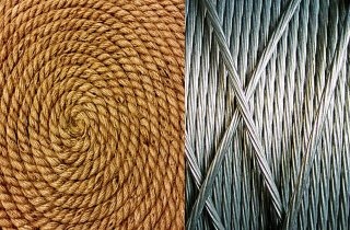
Rope drive is used where a large amount of power is needed to transfer for a long distance (more than 8m). The rope runs over a grooved pulley.
There are two types rope drive Fibres Rope and Wire Rope.
Advantages of the rope drive
Disadvantages of the rope drive
How is rope drive different from Belt drive and Chain drive?
A Rope Drive uses a rope to transmit power from one system to another, for e.g. in pulleys over a well. It is different from a belt drive because it does not use a belt to transmit power. A rope drive is expected to give a smoother operation and less noise than chain drive, but can have higher power losses.
Gear:
A gear is a kind of machine element in which teeth are cut around cylindrical or cone shaped surfaces with equal spacing. By meshing a pair of these elements, they are used to transmit rotations and forces from the driving shaft to the driven shaft. Gears can be classified by shape as involute, cycloidal and trochoidal gears. Also, they can be classified by shaft positions as parallel shaft gears, intersecting shaft gears, and non-parallel and non-intersecting shaft gears.
Type of gear:
Following are the different types of gears:
- Spur Gears
- Helical Gears
- Double Helical or Herringbone Gears.
- Spiral gears
- Bevel Gears
- Worm Gears
1) Parallel gears - As indicated by the name, parallel configurations involve gears connected to rotating shafts on parallel axes within the same plane. The rotation of the driving shaft (and the driving gear) is in the opposite direction to that of the driven shaft (and driven gear), and the efficiency of power and motion transmission is typically high.
a) Spur gear:
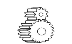
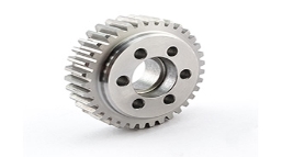
Spur gears transmit power through shafts that are parallel. The teeth of the spur gears are parallel to the shaft axis. This causes the gears to produce radial reaction loads on the shaft, but not axial loads. Spur gears tend to be noisier than helical gears because they operate with a single line of contact between teeth. While the teeth are rolling through mesh, they roll off of contact with one tooth and accelerate to contact with the next tooth. This is different than helical gears, which have more than one tooth in contact and transmit torque more smoothly.
b) Helical Gear:
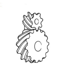
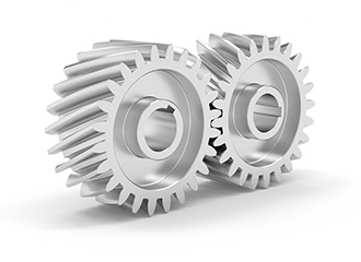
Helical gears have teeth that are oriented at an angle to the shaft, unlike spur gears which are parallel. This causes more than one tooth to be in contact during operation and helical gears are capable of carrying more load than spur gears. Due to the load sharing between teeth, this arrangement also allows helical gears to operate smoother and quieter than spur gears. Helical gears produce a thrust load during operation which needs to be considered when they are used. Most enclosed gear drives use helical gears.
c) Double Helical Gear:
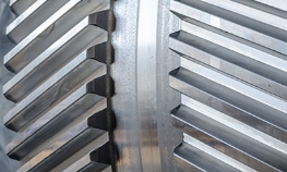
Double helical gears are a variation of helical gears in which two helical faces are placed next to each other with a gap separating them. Each face has identical, but opposite, helix angles. Employing a double helical set of gears eliminates thrust loads and offers the possibility of even greater tooth overlap and smoother operation. Like the helical gear, double helical gears are commonly used in enclosed gear drives.
d) Herringbone Gear
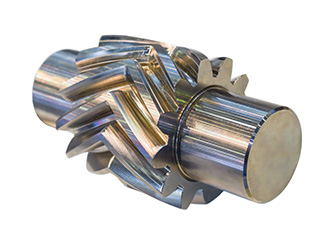
Herringbone gears are very similar to the double helical gear, but they do not have a gap separating the two helical faces. Herringbone gears are typically smaller than the comparable double helical, and are ideally suited for high shock and vibration applications. Herringbone gearing is not used very often due to their manufacturing difficulties and high cost.
2) Intersecting gears
Bevel gear: Bevel gears are most commonly used to transmit power between shafts that intersect at a 90 degree angle. They are used in applications where a right angle gear drive is required. Bevel gears are generally more costly and are not able to transmit as much torque, per size, as a parallel shaft arrangement.
Bevel gear transmits power between two intersecting shafts at any angle or non-intersecting shaft. they are classified as straight and spiral tooth bevel and hypoid gears. These are gears cut from conical blanks and connect intersecting shaft axes.
The connecting shaft is generally at 90°and sometimes one shaft drives a bevel gear which is mounted on a through the shaft resulting in two output shafts. The point of intersection of the shaft is called the apex and the teeth if the two gears converge at the apex.
There are several types of bevel gears available differentiated mainly by their tooth design. Some of the more common types of bevel gears include straight, spiral, and Zero bevel gears.
a) Straight Bevel Gears
The most commonly used of the bevel gear tooth designs due to its simplicity and, consequently, its ease of manufacturing, straight bevel teeth are designed such that when properly matched straight bevel gears come into contact with one another, their teeth engage together all at once rather than gradually. As is the issue with spur gears, the engagement of straight bevel gear teeth results in high impact, increasing the level of noise produced and amount of stress experienced by the gear teeth, as well as reducing their durability and lifespan.
b) Spiral Bevel Gears
In spiral bevel gears, the teeth are angled and curved to provide for more gradual tooth engagement and more tooth-to-tooth contact than with a straight bevel gear. This design greatly reduces the vibration and noise produced, especially at high angular velocities (>1,000 rpm). Like helical gears, spiral bevel gears are available with right-hand or left-hand angled teeth. As is also the case with helical gears, these gears are more complex and difficult to manufacture (and, consequently, more expensive), but offer greater tooth strength, smoother operation, and lower levels of noise during operation than straight bevel gears.
Additional Bevel Gear Designs
Other than the types mentioned above, there are several other designs of bevel gears available including mitre, crown, and hypoid gears.
c) Miter: Miter gears are bevel gears which, when paired, have a gear ratio of 1:1. This gear ratio is a result of pairing two miter gears with the same number of teeth. This type of bevel gear is used in applications which require a change only to the axis of rotation with speed remaining constant. When two bevel gear has their axes at right angles and is equal sizes, they are called miter gears.
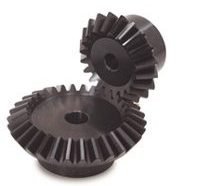
d) Crown: Crown gears, also referred to as face gears, are cylindrical (rather than conical) bevel gears with teeth cut or inserted perpendicular to the gear face. Crown gears can be paired either with other bevel gears or, depending on the tooth design, spur gears.
e) Hypoid: Originally developed for the automobile industry, hypoid gears, unlike the previously mentioned types, are a type of spiral bevel gear used for non-parallel, non-intersecting configurations. This design allows for components to be placed lower, allowing for more space in the sections above. Employing curved and angled teeth similar to those used in spiral bevel gears, hypoid gears are even more complex and, consequently, more difficult (and costly) to manufacture.
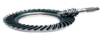
Hypoid gears look very much like a spiral bevel gear but they operate on shafts which do not intersect, which is the case with a spiral bevel gear. In the hypoid arrangement because the pinion is set on a different plane than the gear, the shafts are supported by the bearings on either end of the shaft.
3) Non-intersecting and Non-Parallel gears.
a) Worm Gears: worm gear pairs are comprised of a worm wheel typically a cylindrical gear paired with a worm i.e., a screw-shaped gear. These gears are used to transmit motion and power between non-parallel, non-intersecting shafts. They offer large gear ratios and capabilities for substantial speed reduction while maintaining quiet and smooth operation.
Worm gears transmit power through right angles on non-intersecting shafts. Worm gears produce thrust load and are good for high shock load applications but offer very low efficiency in comparison to the other gears. Due to this low efficiency, they are often used in lower horsepower applications.
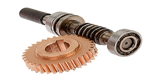
One distinction of worm gear pairs is that the worm can turn the worm wheel, but, depending on the angle of the worm, the worm wheel may not be able to turn the worm. This characteristic is employed in equipment requiring self-locking mechanisms. Some of the disadvantages of worm gears are the low transmission efficiency and the amount of friction generated between the worm wheel and worm gear which necessitates continuous lubrication.
4) Rack and Pinion Gears
A rack and pinion is a pair of gears which convert rotational motion into linear motion and vice versa. A circular gear called “the pinion” engages teeth on a linear “gear” bar called “the rack”.
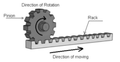
Rotational motion applied to the pinion will cause the rack to move to the side, up to the limit of its travel. The diameter of the gear determines the speed that the rack moves as the pinion turns.
A rack and pinion are commonly found in the steering mechanism of cars or other wheeled, steered vehicles. In a rack railway, the rotation of a pinion mounted on a locomotive or a railcar engages a rack between the rails and pulls a train along a steep slope, machine tools such as lathe machine, drilling machine, planning machine.
Rack and pinion gears are a pair of gears comprised of a gear rack and a cylindrical gear referred to as the pinion. The gear rack can be considered as a gear of infinite radius (i.e., a flat bar) and is constructed with straight teeth cut or inserted on the bar’s surface. Depending on the type of pinion gear with which it is mated, the gear rack’s teeth are either parallel (when mated with spur gears) or angled (when mated with helical gears). For either of these rack designs, rotational motion can be converted into linear motion or linear motion can be converted into rotational motion.
Some of the advantages of a rack and pinion gear pair are the simplicity of the design (and the low cost of manufacturing) and high load carrying capacities. Despite the advantages of this design, gears which employ this approach are also limited by it. For example, transmission cannot continue infinitely in one direction as motion is limited by the designated length of the gear rack. Additionally, rack and pinion gears tend to have a greater amount of backlash (i.e., additional space between mated gear teeth) and, consequently, the teeth experience a significant amount of friction and stress.
Some of the common applications of rack and pinion gear pairs include the steering system of automobiles, transfer systems, and weighing scales.
Gear train – simple and compound epicyclical gear train
A gear train is a mechanical system formed by mounting gears on a frame. when two or more gears mesh together to transmit power from one shaft to another such arrangement is called a gear set or a gear train.
Sometimes two or more gears are made to mesh with each other to transmit power from one shaft to another such a combination is called “gear train of the wheel”. Also, each gear is generally attached to a shaft often gears that are meshed together will be of different sizes in this case the smaller gear is referred to as the pinion and the larger one is simply referred to as the gear.
Following are the different types of gear trains:
1. Simple Gear Trains
In these types of gear trains, the distance between the two wheels is great. the motion from one wheel to another is transmitted by providing one or more intermediate wheels as shown in the figure.
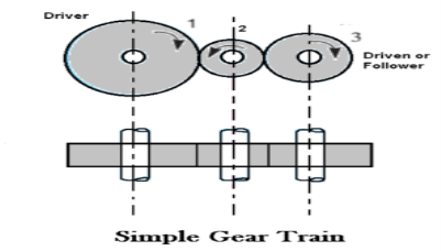
When the number of intermediate wheels is odd, the motion of driver and follower is like as shown in the figure. If the number of intermediate wheels is even the motion of the follower will be in the opposite direction of the driver as shown in the figure.
The speed ratio (or velocity ratio) of gear train is the ratio of the speed of the driver to the speed of the driven or follower and ratio of speeds of any pair of gears in mesh is the inverse of their number of teeth, therefore
Speed ratio: Speed of driver /speed of driven = NO. of teeth on driven /No. of teeth on driver.
Speed ratio = N1/N2 = T2 / T1
The train value may be noted that ratio of the speed of the driven or follower to the speed of the driver is known as train value of the gear train. Mathematically,
Train value: Speed of driven /speed of driver = NO. of teeth on driver /No. of teeth on driven.
Train value = N2 / N1 = T1 / T2
2. Compound Gear Train
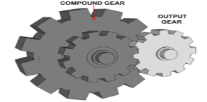
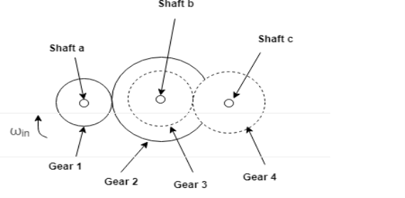
In compound gear train, each intermediate shaft has two wheels fixed to it. These wheels have the same speed. One wheel gears with the drier and the other wheel gears with the follower attached to the next shaft.
Speed ratio: Speed of first driver /speed of last driven = Product of the number of teeth on driven /product of the number of teeth on driver
Speed ratio = N1 / N6 = T2 X T4 X T6 / T1 X T3 X T5
Train value: Speed of last driver /speed of first driven = Product of the number of teeth on driver /product of the number of teeth on driven
3. Reverted Gear Trains
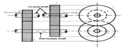
When the axes of the first and last wheels are co-axial the train is known as “reverted gear trains” as shown fig. Since the motion of the first and last wheel is alike, therefore a compound wheel is provided. Since the distance between the centres of the shaft 1 and 2 as well as 3 and 4 is the same.
Speed ratio: Speed of first driver /speed of last driven = Product of the number of teeth on driven /product of the number of teeth on drivers
Epicyclic gear train: the axes of the shaft, over which the gears are mounted, move relative to a fixed axis. A simple epicyclic or planetary gear train is shown the figure.
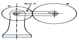
Here wheel A and arm C have a common axis at O1 about which they can rotate. The wheel B meshes with wheel A and has its axis on the arm at O2, about which the wheel B can rotate. If wheel A is fixed and the arm is rotated, the train becomes an “epicyclic gear train”.
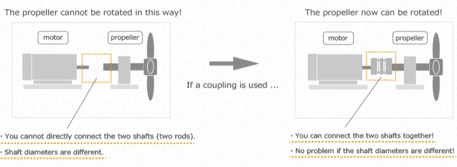
A coupling is a mechanical element part that connects two shafts together to accurately transmit the power from the drive side to the driven side while absorbing the mounting error (misalignment), etc. of the two shafts.
Coupling in the machine industry is interpreted as "a part that connects two shafts together", and is generally called "coupling", "shaft coupling" or "joint".
Power can be transmitted by using a coupling, even between axes of different diameters as shown in the following figures.
Coupling fall into two main categories: Material Flexing and Mechanical Flexing. The material flexible types obtain their flexibility from stretching or compressing a resilient material, such as rubber, or from the flexing of thin metallic discs or grid. Material flexing couplings do not require lubrication, with the exception of grid couplings. The mechanical flexing couplings accept misalignment from rocking, rolling or sliding of metal surfaces. All metal mechanical flexing couplings require lubrication.
Material Flexing Couplings
Material flexing couplings typically do not require lubrication and operate in shear or compression and are able to accept angular, parallel and axial misalignment.
Examples of material flexing couplings are jaw, sleeve, tire, disc, grid and diaphragm couplings.
- Jaw Couplings
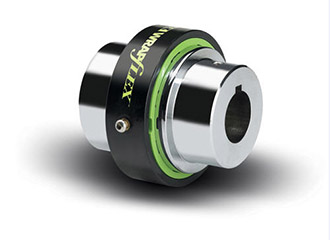
The jaw coupling is a material flexing coupling that transmits torque thru compression of an elastomeric spider insert placed between two intermeshing jaws.
- Sleeve Coupling
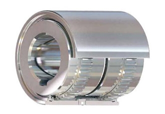
The sleeve coupling transmits low to medium torque between connected equipment in shear through an elastomeric insert with male splines that mate with female hub splines. The insert material is typically EPDM, Neoprene or Hytrel and the insert can be a one or two piece design.
- Tire Coupling
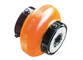
These couplings have a rubber or polyurethane element connected to two hubs. The rubber element transmits torque in shear.
- Disc Coupling
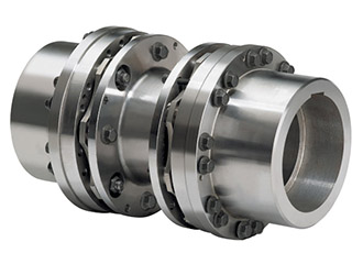
The disc coupling’s principle of operation has the torque transmitted through flexing disc elements. It operates through tension and compression of chorded segments on a common bolt circle bolted alternately between the drive and driven side. These couplings are typically comprised of two hubs, two discs packs, and a centre member. A single disc pack can accommodate angular and axial misalignment. Two disc packs are needed to accommodate parallel misalignment.
• Allows angular parallel and axial misalignment
• is a true limited end float design
• A zero backlash design
• High speed rating and balance
- Diaphragm Coupling
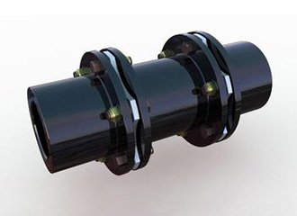
Diaphragm couplings utilize a single or a series of plates or diaphragms for the flexible members. It transmits torque from the outside diameter of a flexible plate to the inside diameter, across the spool or spacer piece, and then from inside to outside diameter. The deflection of the outer diameter relative to the inner diameter is what occurs when the diaphragm is subject to misalignment. For example, axial displacement attempts stretch the diaphragm which results in a combination of elongations and bending of the diaphragm profile.
• Allows angular, parallel and high axial misalignments
• Used in high torque, high speed applications
Mechanical Flexing Couplings
The mechanical flexing couplings accept misalignment from rocking, rolling or sliding of metal surfaces. All metal mechanical flexing couplings require lubrication.
Examples of mechanical flexing couplings are gear, grid and roller chain couplings.
- Gear Couplings
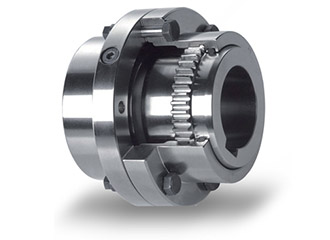
Gear couplings transmit the highest amount of torque and the highest amount of torque in the smallest diameter of any flexible coupling.
Each coupling consists of two hubs with crowned external gear teeth. The hubs mesh with two internally splined flanged sleeves that are bolted together. Gear couplings accommodate angular and axial misalignment by the rocking and sliding of the crowned gear teeth against the mating sleeve teeth. Parallel misalignment is accommodated by having two adjacent hub/sleeve flex points. Gear couplings require periodic lubrication depending on the application. They are sensitive to lubrication failures but if properly installed and maintained, these couplings have a service life of 3 to 5 years and in some cases they can last for decades.
- Grid Couplings
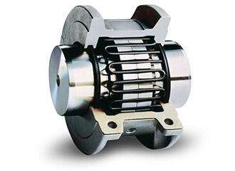
Grid couplings consist of 2 radially slotted hubs that mesh with a serpentine strip of spring steel the grid provides torsional damping and flexibility of an elastomer but the strength of steel. Grid couplings transmit torque and accommodate angular, parallel and axial misalignment from one hub to the other through the rocking and sliding of a tapered grid in the mating hub slots. The grid cross section is generally tapered for better hub contact and easier assembly. As there is movement between contacting hub and grid metal parts, lubrication is required.
- Roller Chain Coupling
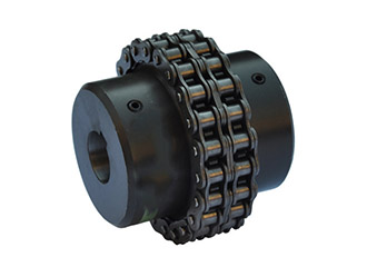
Roller Chain type couplings consist of two radially sprocketed hubs that engage a strand of double pitch roller chain. Chain couplings are used for low to moderate torque and speed applications. The meshing of the sprocket teeth and chain transmits torque and the associated clearances accommodate angular, parallel and axial misalignment. Chain couplings require periodic lubrication depending on the application. The lubrication is typically brushed onto the chain and a cover is used to help keep the lubrication on the coupling.
BRAKES:
A brake is defined as a mechanical device, which is used to absorb the energy possessed by a moving system or mechanism by means of friction.
CLASSIFICATION OF BRAKES:
(i) MECHANICAL BRAKES:
Operated by mechanical means such as levers, springs and pedals.
(ii) HYDRAULIC AND PNEUMATIC BRAKES
Operated by fluid pressure such as oil pressure or air pressure.
(iii) ELECTRICAL BRAKES
Operated by magnetic forces and which include magnetic particle brakes, hysteresis brakes and eddy – current brakes.
BLOCK BRAKE WITH SHORT SHOE:
A block brake consists of a simple block, which is pressed against the rotating drum by means of a lever as shown in figure,
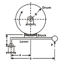
The friction between the block and the brake drum causes the retardation of the drum.
The angle of contact between the block and the brake drum is usually small. When it is less than 45ºC .
the intensity of pressure between the block and brake drum is uniform.
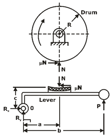
The forces acting on the brake drum,
 ,
,
Where,
Mt = braking – torque (N-mm)
R= radius of the brake drum (mm)
μ=coefficient of friction,
N= normal reaction (N),
Depending upon the magnitude of coefficient of friction and location of hinge pin , there are three different cases:
Case I: a > μc
The friction force helps to reduce the magnitude of the actuating force .
Case II: a = μc
The actuating force is zero. This indicates that no external force is required for the braking action. Such a brake is called a ‘self – locking’ brake.
Case III: a < μc
The actuating force becomes negative.
This is a dangerous operating condition, resulting in uncontrolled braking and grabbing.
BLOCK BRAKE WITH LONG SHOE:
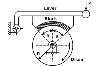
Fig.: Schematic of Long-shoe block brake


and, θ is the semi – cone angle.
SIMPLE BAND BRAKES:
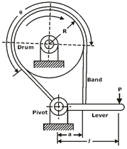
The working of the steel band is similar to that of a flat belt operating at zero velocity.
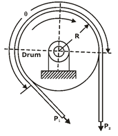
Fig.: FBD of band

Torque absorbed by the brake is given by,

DIFFERENTIAL BAND BRAKES:
The free – body diagram of forces acting on the band and the lever is shown in figure,
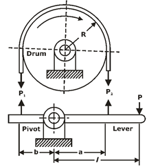
Fig.: FBD of Differential band brake

For the self – locking condition,

DISK BRAKES:
A disk brake is similar to a plate clutch, except that one of the shafts is replaced by a fixed member.
Advantages of disk brakes
CLUTCH:
The clutch is a mechanical device, which is used to connect or disconnect the source of power from the remaining parts of the power transmission system at the will of the operator.
CLASSIFICATION OF CLUTCH:
(i) Positive Contact Clutches:
(ii) Friction Clutches:
(iii) Electromagnetic Clutches:
(iv) Fluid Clutches:
TORQUE TRANSMITTING CAPACITY OF SINGLE-PLATE CLUTCH:
A friction disk of a single plate clutch is shown in figure,
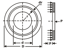
Notations used
D= Outer diameter of friction disk (mm)
d = inner diameter of friction disk (mm)
P= intensity of pressure at radius (mm)
F= total operating force (N)
Mt = torque transmitted by the clutch (N-mm)

Two theories are used to obtain the torque capacity of the clutch.
They are called uniform pressure theory and uniform wear theory.
UNIFORM PRESSURE THEORY:
In case of new clutches employing a number of springs, the pressure remains constant over the entire surface area of the friction disk.

UNIFORM WEAR THEORY:
It is assumed that the wear is uniformly distributed over the entire surface area the friction disk.
When the wear is uniform,
P r=Constant
In this case, P is inversely proportional to r Therefore, pressure is maximum at the inner radius and minimum at the outer periphery.


For uniform wear theory or worn – out clutches:

For uniform pressure theory or new clutches:

Note:
Number of disks = number of pairs of contacting surfaces+1=Z+1
Suppose,
Z1= number of disks on driving shaft
Z2 = number of disks on driven shaft
Z1 +Z2 = number of pairs of contacting surfaces + 1
or number of pairs of contacting surfaces Z1 +Z2 –1
CONE CLUTCHES:
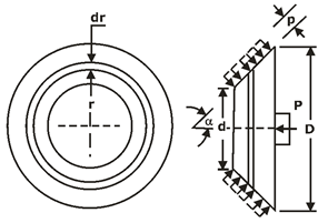
Fig.: Analysis of cone clutch
In case of uniform pressure theory,

In case of uniform wear theory,

Where, α is the semi cone angle.
Centrifugal clutch:
It consists of number of shoes on the inside of a rim of the pulley. The outer surface of the shoes is covered with a friction material.
These shoes, which can move radially in guides, are held against the boss on the driving shaft by means of spring.
The springs exert a radially inward force which is assumed constant.
the torque transmitting capacity of the clutch is given by,

Notations used
rg = radius of the drum (mm)
rd = radius of the centre of gravity of the shoe in engaged position (mm)
m= mass of each shoe
Pcf = centrifugal force (N)
Ps = spring force (N)
z= number of shoes
ω2 =running speed (rad/s)
ω1= speed at which engagement starts (rad/s)
Introduction to Robotics:
The anatomy of robot is also known as structure of robot. The basic components or sections in anatomy of robots are as follows.
The RIA (Robotics Industries Association) has officially given the definition for Industrial Robots An .Industrial According Robot is are programmable, to RIA, multifunctional “ manipulator designed to move materials, parts, tools, or special devices through variable programmed motions for the performance of a
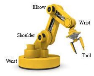
The Anatomy of Industrial Robots deals with the assembling of outer components of a robot such as wrist, arm, and body. Before jumping into Robot Configurations, here are some of the key facts about robot anatomy.
End Effectors: A hand of a robot is considered as end effectors. The grippers and tools are the two significant types of end effectors. The grippers are used to pick and place an object, while the tools are used to carry out operations like spray painting, spot welding, etc. on a work piece.
Robot Joints: The joints in an industrial robot are helpful to perform sliding and rotating movements of a component.
Manipulator: The manipulators in a robot are developed by the integration of links and joints. In the body and arm, it is applied for moving the tools in the work volume. It is also used in the wrist to adjust the tools.
Kinematics: It concerns with the assembling of robot links and joints. It is also used to illustrate the robot motions.
The manipulator of an industrial robot is constructed of a series of joints and links. Robot anatomy is concerned with the types and sizes of these joints and links and other aspects of the manipulator's physical construction.
1 Joint and Links
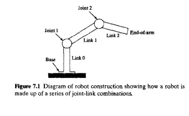
A joint of an industrial robot is similar to a joint in the human body: It provides relative motion between two parts of the body. Each joint, or axis as it is sometimes called, provides the robot with a so called degree-of-freedom (d.o.f.) of motion. In nearly all cases, only one degree of freedom is associated with a joint. Robots are often classified according to the total number of degrees-of-freedom they possess. Connected to each joint are two links, an input link and an output link. Links are the rigid components of the robot manipulator. The purpose of the joint is to provide controlled relative movement between the input link and the output link. Most robots are mounted on a stationary base on the floor. Let us refer to that base and its connection to the first joint as link 0.1t is the input link to joint 1, the first in the series of joints used in the construction of the robot. The output link of joint 1 is link 1. Link 1 is the input link to joint 2, whose output link is link 2, and so forth. This joint-link numbering scheme is illustrated in Figure 7.1.
Nearly all industrial robots have mechanical joints that can be classified into one of five types: two types that provide translational motion and three types that provide rotary motion. These joint types are illustrated in Figure 7.2 and are based on a scheme described in [6]. The five joint types are: Linear joint (type L-joint).The relative movement between the input link and the output link is a translational sliding motion, with the axes of the two links being parallel.
Orthogonal Joint (type U joint). This is also a translational sliding motion, but the input and output links are perpendicular to each other during the move.
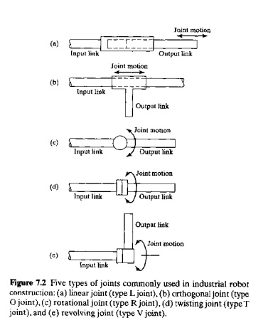
Rotational Join (type R joint). This type provides rotational relative motion, with the axis of rotation perpendicular to the axes of the input and output links.
Twisting joint (type T joint) This joint also involves rotary motion, but the axis or rotation is parallel to the axes of the two links.
Revolving joint (type V joint, V from the "v' in revolving). In this joint type, the axis 0' the input link is parallel to the axis of rotation of the joint. And the axis of the output link is perpendicular to the axis of rotation.
Each of these joint types has a range over which it can be moved. The range for a translational joint is usually less than a meter. The three types of rotary joints may have a range as small as a few degrees or as large as several complete turns
2 Common Robot Configurations
A robot manipulator can he divided into two sections: a body-and-arm assembly and a wrist assembly. There are usually three degrees-of-freedom associated with the body-and-arm, and either two or three degrees-of-freedom associated with the wrist. At the end of the manipulator's wrist is a device related to the task that must be accomplished by the robot. The device, called an end effector (Section 7.3), is usually either (1) a gripper for holding a work-part or (2) a tool for performing some process. The body-and-arm of the rotor is used to position the end effector. And the robot's wrist is used to orient the end effector.
Body-and-Arm Configurations. Given the five types of joints defined above, there are 5 x 5 x 5 = 125 different combinations of joints that can be used to design the body-and-arm assembly for a three-degree-of-freedom robot manipulator. In addition, there are design variations within the individual joint types [e.g.. physical size of the joint and range of motion). It is somewhat remarkable, therefore, that there are only five basic configurations commonly available in commercial industrial robots. These five configurations are:
Polar configuration. This configuration (Figure 7.3) consists of a sliding arm (L joint) actuated relative to the body, that can rotate about both a vertical axis (1' joint) and a horizontal axis (R joint).
Cylindrical configuration. This robot configuration (Figure 7.4) consists of a vertical column, relative to which an arm assembly is moved up or down. The arm can be moved in and out relative to the axis of the column. Our figure shows one possible way in which this configuration can be constructed, using a T joint to rotate the column about its axis An 1. joint is used to move the arm assembly vertically along the column, while an 0 joint is used to achieve radial movement of the ann,
Cartesian coordinate robot. Other names for this configuration include rectilinear robot and iyz robot. As shown in Figure 7 5,it is composed of three sliding joints, two of which are orthogonal.
4, Jointed-arm-robot. This robot manipulator (Figure 7.6) has the general configuration of a human arm. The jointed arm consists of a vertical column that swivels about the
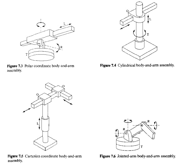
base using a T joint. At the top of the column is a shoulder joint (shown as an R joint in our figure), whose output link connects to an elbow joint (another R joint)
5. SCARA. SCARA is an acronym for Selective Compliance Assembly Robot Arm. This configuration (Figure 7.7) is similar to the jointed arm robot except that the shoulder and elbow rotational axes are vertical, which means that the arm is very rigid in the vertical direction. but compliant in the horizontal direction. This permits the robot to perform insertion tasks (for assembly) in a vertical direction, where some side-to-side alignment may be needed to mate the two parts properly.
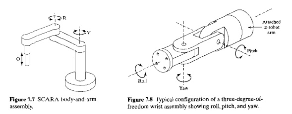
Wrist Configurations. The robot's wrist is used to establish the orientation of the end effector. Robot wrists usually consist of two or three degrees-of-freedom. Figure 7.8 illustrates one possible configuration for a three-degree-of-freedom wrist assembly. The three joints are defined as: (1) roll, using a T joint to accomplish rotation about the robot's arm axis: (2) pitch, which involves up-and-down rotation, typically using a R joint; and (3) yaw, which involves right-and-left rotation, also accomplished by means of an R-joint, A two-d.o.f wrist typically includes only roll and pitch joints (T and R joints).
To avoid confusion in the pitch and yaw definitions, the wrist roll should be assumed in its centre position, as shown in our figure. To demonstrate the possible confusion, consider a two-jointed wrist assembly. With the roll joint in its centre position, the second joint (R joint) provides up-and-down rotation (pitch). However, if the roll position were 90 degrees from centre (either clockwise or counter clockwise), the second joint would provide a right-left rotation (yaw).
The SCARA robot configuration (Figure 7.7) is unique in that it typically does not have a separate wrist assembly. As indicated in our description, it is used for insertion type assembly operations in that the insertion is made from above. Accordingly. The orientation requirements are minimal, and the wrist is therefore not needed. Orientation of the object to be inserted is sometimes required, and an additional rotary joint can be provided for this purpose. The other four body-and-arm configurations possess wrist assemblies that almost always consist of combinations of rotary joints of types Rand T.
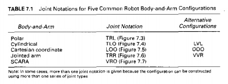
Joint Notation System. The letter symbols for the five joint types (L, 0, R, T, and V) can be used to define a joint notation system for the robot manipulator. In this notation system, the manipulator is described by the joint types that make up the body-and-arm assembly. followed by the joint symbols that make lip the wrist. For example, the notation TLR: TR represents a five degree-of-freedom manipulator whose body-and-arm is made up of a twisting joint (joint 1 = T),a linear joint (joint 2 = L), and a rotational joint (joint 3 = R). The wrist consists of two joints, a twisting joint (joint 4 = T) and a rotational joint (joint 5 '" R). A colon separates the body-and-arm notation from the wrist notation. Typical joint notations for the five common body-and-arm configurations are presented in Table 7.1. Common wrist joint notations are TRR and TR.
Work Volume. The work volume (the term work envelope is also used) of the manipulator is defined as the envelope or space within which the robot can manipulate the end of its wrist. Work volume is determined by the number and types of joints in the manipulator (body-and-arm and wrist), the ranges of the various joints, and the physical sizes of the links. The shape of the work volume depends largely on the robot's configuration. A polar configuration robot tends to have a partial sphere as its work volume, a cylindrical robot has a cylindrical work envelope. and a Cartesian coordinate robot has a rectangular work volume.
3 Joint Drive Systems
Robot joints are actuated using any of three possible types of drive systems: (1) electric, (2) hydraulic, or (3) pneumatic. Electric drive systems use electric motors as joint actuators (e.g., servomotors or stepping motors, the same types of motors used in NC positioning systems, Chapter 6), Hydraulic and pneumatic drive systems use devices such as linear pistons and rotary vane actuators to accomplish the motion of the joint.
Pneumatic drive is typically limited to smaller robots used in simple material transfer applications. Electric drive and hydraulic drive are used on more-sophisticated industrial robots. Electric drive has become the preferred drive system in commercially available robots, as electric motor technology has advanced in recent years. It is more readily adaptable to computer control, which is the dominant technology used today for robot controllers. Electric drive robots are relatively accurate compared with hydraulically powered robots. By contrast, the advantages of hydraulic drive include greater speed and strength.
The drive system, position sensors (and speed sensors if used), and feedback control systems for the joints determine the dynamic response characteristics of the manipulator. The speed with which the robot can achieve a programmed position and the stability of its motion are important characteristics of dynamic response in robotics. Speed refers to the absolute velocity of the manipulator at its end-of-arm. The maximum speed of a large robot is around 2 rn/sec (6 ft/sec). Speed call be programmed into the work cycle so that different portions of the cycle are carried out at different velocities. What is sometimes more important than speed is the robot's capability to accelerate and decelerate in a controlled manner. In many work cycles. Much of the robot's movement is performed in a confined region of the work volume; hence, the robot never achieves its top-rated velocity. In these cases, nearly all of the motion cycle is engaged in acceleration and deceleration rather than in constant speed. Other factors that influence speed of motion are the weight (mass) of the object that is being manipulated and the precision with which the object must be located at the end of a given move. A term that takes au of these factors into consideration is speed of response, that refers to the time required for the manipulator to move from one point in space to the next. Speed of response is important because it influences the robot's cycle time, that in turn affects the production rate in the application. Stability refers to the amount of overshoot and oscillation that occurs in the robot motion at the end-of-arm as it attempts to move to the next programmed location. More oscillation in the motion is an indication of less stability. The problem is that robots with greater stability are inherently slower in their response, whereas faster robots are generally less stable.
Load carrying capacity depends on the robot's physical size and construction as well as the force and power that can be transmitted to the end of the wrist. The weight carrying capacity of commercial robots ranges from less than 1 kg up to approximately 900 kg (2000 lb). Medium sized robots designed for typical industrial applications have capacities in the range 10 to 45 kg (25 to 100 Ib). One factor that should be kept in mind when considering load carrying capacity is that a robot usually works with a tool or gripper attached to its wrist Grippers are designed to grasp and move objects about the work cell. The net load carrying capacity of the robot is obviously reduced by the weight of the gripper. If the robot is rated at a 10 kg (22 lb} capacity and the weight of the gripper is 4 kg (9 lbs}, then the net weight carrying capacity is reduced to 6 kg (13Ib).
