UNIT 1
OSCILLATION & WAVES
Simple Harmonic Motion or SHM is defined as a motion in which the restoring force is directly proportional to the displacement of the body from its mean position. The direction of this restoring force is always towards the mean position.
Simple harmonic motion can be described as an oscillatory motion in which the acceleration of the particle at any position is directly proportional to the displacement from the mean position. It is a special case of oscillatory motion.
All the Simple Harmonic Motions are oscillatory and also periodic but not all oscillatory motions are SHM. Oscillatory motion is also called the harmonic motion of all the oscillatory motions wherein the most important one is simple harmonic motion (SHM).
In this type of oscillatory motion displacement, velocity and acceleration and force vary (w.r.t time) in a way that can be described by either sine (or) the cosine functions collectively called sinusoids.
Simple Harmonic Motion
When a particle moves to and fro about a fixed point (called equilibrium position) along with a straight line then its motion is called linear Simple Harmonic Motion.
For Example: spring-mass system
Conditions for Linear SHM:
The restoring force or acceleration acting on the particle should always be proportional to the displacement of the particle and directed towards the equilibrium position.
F∝−x
a∝−x
x – displacement of particle from equilibrium position.
F – Restoring force
A–acceleration
Let us consider a simplest mechanical system executing simple harmonic motion. We will solve differential equation for SHM.
MECHANICAL SIMPLE HARMONIC OSCILLATORS
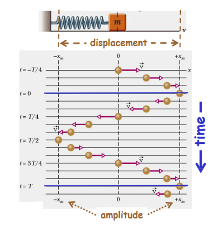
The figure-1 depicts simple mechanical oscillator having mass attached to the spring. This structure is similar to Pendulum. It is also known as harmonic oscillator.
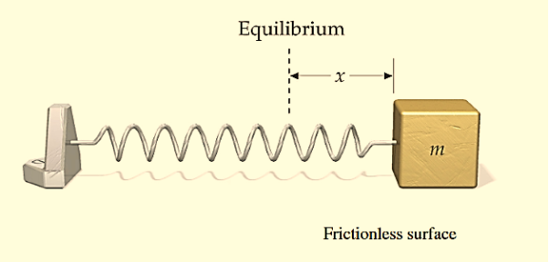
Figure: 1
If a body attached to a spring is displaced from its equilibrium position, the spring exerts a restoring force on it, which tends to restore the object to the equilibrium position. This force causes oscillation of the system, or periodic motion.
When the restoring force is directly proportional to the displacement from equilibrium, the resulting motion is known as simple harmonic motion and the oscillator is known as Harmonic Oscillator.
In this type of system body itself changes its position.
For mechanical oscillation two things are especially responsible i.e. Inertia & Restoring force.
Differential Equation
A particle is said to be execute simple harmonic oscillation is the restoring force is directed towards the equilibrium position and its magnitude is directly proportional to the magnitude and displacement from the equilibrium position. If F is the restoring force on the oscillator when its displacement from the equilibrium position is x, then
F –x
–x
Here, the negative sign implies that the direction of restoring force is opposite to that of displacement of body i.e. towards equilibrium position.
F= -kx ............. (1)
Where, k= proportionality constant called force constant.
An example of such a simple system is the mass m, attached to a spring of stiffness k.
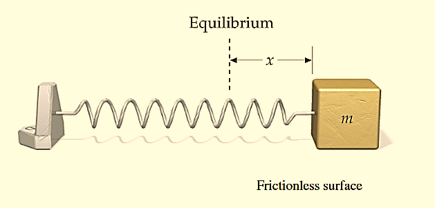
Figure: 2
In the case of a mass on a spring, the restoring force for small oscillations obeys Hooke’s law:
F=−kx ………….(1)
where k is the stiffness of the spring. Here the coordinate x=0 corresponds to the point of equilibrium, in which the force of gravity is balanced by the initial tension of the spring.
Then, according to Newton’s second law
F= ma = m  ………….(2)
From equation (1) and (2)
m  = −kx
= −kx
m  + kx = 0
 +
+  x = 0………….(3)
Equation (3) can also be written as
⇒x′′+ x = 0
x = 0
 +ω2x = 0………….(4)
or
⇒x′′+ω2x=0
On comparing equation (3) and (4)
ω2 =
ω= ………….(5)
Solution of differential equation is
x= Acosωt………….(4)
or
x = Acos
Thus, the mass on the spring will perform undamped harmonic oscillations with the circular frequency
ω=
The time period of oscillation, respectively, will be equal to
T= =2π
=2π
Phase
The form of Equations (4) implies that over each period of oscillation, as the time t increases its value bythe fixed amount T,the oscillator passes through a complete cycle of x values. Now, during such a cycle, thequantity 2πt/T (i.e. the argument of the sine and cosine functions) increases by 2π, and each additional increment of 2π corresponds to another complete oscillation.
In this way the argument of the sine or cosine function behaves rather like an angle measured in radians, since that too would complete an additional cycle for each increase of 2π radians (or 360°). Of course, there’s not really any angle involved here since the motion is linear and the quantity 2πt/T has no units; what the argument of the periodic sine or cosine function tells us is the stage that the moving particle has reached within its own cycle of oscillation. Nonetheless, the argument of the periodic function is often referred to as the phase angle or simply the phase of the motion and is as likely to be expressed in radians (or the corresponding number of degrees) as it is to be given as a unit less number.
A phase of 0 corresponds to the start of a cycle, a phase of 2π to the start of the next cycle, 4π the next, and soon. If the motion is halfway through the first cycle the phase is π.
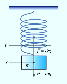
Figure: 3
Displacement as a function of time in SHM is given by
x(t)=Acos(2πt/T+φ)=Acos(ωt+φ)
whereφ is the phase or phase angle.
The Velocity is given by
v(t)=−Aωsin(ωt+φ)=−vmaxsin(ωt+φ),wherevmax=Aω=A
The Acceleration is a(t)=−Aω2cos(ωt+φ)=−amaxcos(ωt+φ), where amax=Aω2=A
A similar analysis of other oscillatory system which execute Simple harmonic motion. a simple pendulum – leads to the following formula for the oscillation period:
T=2π
where L is the length of the pendulum, g is the acceleration of gravity.
In the case of a compound or physical pendulum, the period of oscillation is given by
T=2π
where I is the moment of inertia of the pendulum about the pivot point, m is the mass of the pendulum, a is the distance between the pivot point and the center of mass of the pendulum.
Example: oscillation of mass spring system, oscillation of fluid-column in a U-tube, oscillation of simple pendulum, rotation of earth around the sun, oscillation of body dropped in a tunnel along earth diameter, oscillation of floating cylinder, oscillation of a circular ring suspended on a nail, oscillation of atoms and ions of solids, vibration of swings etc.
DAMPED OSCILLATIONS
We have seen that the total energy of a harmonic oscillator remains constant. Once started, the oscillations continue forever with a constant amplitude (which is determined from the initial conditions) and a constant frequency (which is determined by the inertial and elastic properties of the system). Simple harmonic motions which persist indefinitely without loss of amplitude are called free or undamped.
However, observation of the free oscillations of a real physical system reveals that the energy of the oscillator gradually decreases with time and the oscillator eventually comes to rest. For example, the amplitude of a pendulum oscillating in the air decreases with time and it ultimately stops. The vibrations of a tuning fork die away with the passage of time. This happens because, in actual physical systems, friction (or damping) is always present. Friction resists motion.
The presence of resistance to motion implies that frictional or damping force acts on the system. The damping force acts in opposition to the motion, doing negative work on the system, leading to a dissipation of energy. When a body moves through a medium such as air, water, etc. its energy is dissipated due to friction and appears as heat either in the body itself or in the surrounding medium or both.
There is another mechanism by which an oscillator loses energy. The energy of an oscillator may decrease not only due to friction in the system but also due to radiation. The oscillating body imparts periodic motion to the particles of the medium in which it oscillates, thus producing waves. For example, a tuning fork produces sound waves in the medium which results in a decrease in its energy.
All sounding bodies are subject to dissipative forces, or otherwise, there would be no loss of energy by the body and consequently, no emission of sound energy could occur. Thus, sound waves are produced by radiation from mechanical oscillatory systems. The electromagnetic waves are produced by radiations from oscillating electric and magnetic fields.
The effect of radiation by an oscillating system and of the friction present in the system is that the amplitude of oscillations gradually diminishes with time. The reduction in amplitude (or energy) of an oscillator is called damping and the oscillation are said to be damped.
When the energy of a oscillating system is gradually dissipated by friction and other resistances, the oscillations are said to be damped. The oscillations gradually reduce or change in frequency or intensity or cease and the system rests in its equilibrium position.
Damped oscillations refer to oscillations where the oscillating object loses its energy to the surroundings.
Damping, in physics, restraining of vibratory motion, such as mechanical oscillations, noise, and alternating electric currents, by dissipation of energy. Unless a child keeps pumping a swing, its motion dies down because of damping. Shock absorbers in automobiles and carpet pads are examples of damping devices.
A system may be so damped that it cannot oscillate. Critical damping just prevents oscillation or is just sufficient to allow the object to return to its rest position in the shortest period of time.
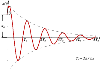
Figure: 4
There are many types of mechanical damping. Friction, also called in this context dry, or Coulomb, damping, arises chiefly from the electrostatic forces of attraction between the sliding surfaces and converts mechanical energy of motion, or kinetic energy, into heat. The motion of a oscillating body is also checked by its friction with the gas or liquid through which it moves.
WAVE EQUATION OF DAMPED VIBRATION
In real systems, there is always a resistance or friction, which leads to a gradual damping of the oscillations. In many cases, the resistance force (denoted by FC) is proportional to the velocity of the body, that is
FC=−cx′.
Then, taking into account the force of resistance, the differential equation for the “mass-spring” system is written as
mx′′+cx′+kx=0,⇒x′′+  x′+
x′+ x=0
x=0
We introduce the following notations:  =2β,
=2β,  =
= . Here ω0 is the natural frequency of the undamped oscillator (previously, we denoted it as ω), β is the damping coefficient. In the new notations, the differential equation looks like
x′′+2βx′+ x=0.
x=0.
We will seek the solution of this equation as a function
x(t)=Aeλt.
The derivatives are given by
x′(t)=Aλeλt, x′′(t)=Aλ2eλt.
Substituting this into the differential equation, we obtain the algebraic characteristic equation:
Aλ2eλt+2βAλeλt+ Aeλt=0,
⇒λ2+2βλ+ =0.
=0.
The roots of this equation are
D=4β2−4 ,
,
It can be seen that depending on the sign of the radicand β2− , there may be three different types of solutions.
Case 1.Overdamping or Heavy Damping: β>ω0
When resistance to motion is very strong, the system is said to be heavily damped. Can you name a heavily damped system of practical interest? Springs joining wagons of a train constitute the most important heavily damped system. In your physics laboratory, vibrations of a pendulum in a viscous medium such as thick oil and motion of the coil of a dead beat galvanometer are heavily damped systems.
In this case (the case of strong damping), the radicand is positive: β2> . The roots of the characteristic equation are real and negative. The general solution of the differential equation has the form
x(t)=C1eλ1t+C2eλ2t,
where the coefficients C1,C2, as usual, depend on the initial conditions.
It follows from this expression that there are no oscillations and the system returns to equilibrium exponentially, i.e. aperiodically (Figure 5).
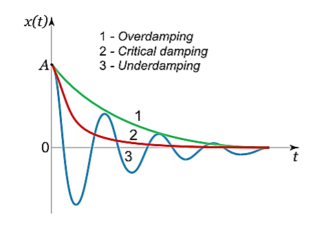
Figure 5
Case 2. Critical Damping: β=ω0
You may have observed that on hitting an isolated road bump, a car bounces up and down and the occupants feel uncomfortable. To minimise this discomfort, the bouncing caused by the road bumps must be damped very rapidly and the automobile is restored to equilibrium quickly. For this we use critically damped shock absorbers. Critical damping is also useful in recording instruments such as a galvanometer (pointer type as well as suspended coil type) which experience sudden impulses. We require the pointer to move to the correct position in minimum time and stay there without executing oscillations. Similarly, a ballistic galvanometer coil is required to return to zero displacement immediately.
In the limiting case when β=ω0, the roots of the characteristic equation are real and coincide:
λ1=λ2=−β=−ω0.
Here the solution is given by the formula
x(t)=(C1t+C2)
In this mode, the value of x(t) may even increase at the beginning of the process because of the linear factor C1t+C2. But in the end the deflection x(t) decreases rapidly due to the exponential decay with a characteristic time τ=2π/ω0.
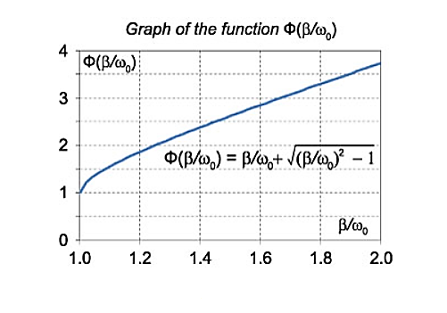
Note that in this critical mode the relaxation occurs faster than in the case of the aperiodic damping (Case 1). Indeed, in this mode the relaxation time will be determined by the smaller (in absolute value) root λ1, and will be given by the formula

The function Φ(β/ω0) included in this expression is monotonically increasing. It is always greater than or equal to 1, as shown in Figure 6

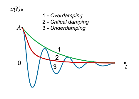
Figure 6
In the critical case (Case 2) the ratio βω0 is 1, and βω0>1 in the case of the aperiodic damping (Case 1). Therefore for the aperiodic damping mode, we can write
τ= Φ(
Φ( )>
)>
Thus, the critical damping mode provides the fastest possible return of the system to equilibrium. This is often used, for example, in door closing mechanisms.
Case 3.Underdamping or Light Damping β<ω0
Here the roots of the characteristic equation are complex conjugate:
λ1,2=−β±i√
The general solution of the differential equation is oscillatory in nature and can be written as
x(t)=e−βt[C1cos(ω1t)+C2sin(ω1t)]
where the oscillation frequency ω1 is equal to
ω1=
The resulting formula can be written in a somewhat different form:
x(t)=Ae−βtcos(ω1t+φ0),
whereφ0 is the initial phase of the oscillations and Acosφ0 is the initial amplitude of the oscillations. We see that classical damped oscillations occur in this mode. Here the oscillation frequency ω1 is less than the harmonic frequency ω0, and the oscillation amplitude decreases exponentially with e−βt.
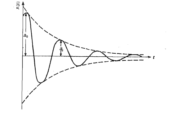
The most convenient way to determine the amount of damping present in a system is to measure the rate at which amplitude of oscillation dies away. Let us consider the damped vibration shown graphically in Figure 7. Let a0 and al be the first two successive amplitudes of oscillation separated by one period.

Figure 7: A damped oscillation. The first two amplitudes arc ao and at
You, will note that these amplitudes lie in the same direction /quadrant. If Tis the period of oscillation, then for a weakly damped oscillator, we can write
 ………(1)
You will note that in the ratio a0/ a1, the larger amplitude is in the numerator. That is why this ratio is called the decrement. It is denoted by the symbol d.
You may now ask: Is the decrement same for any two consecutive amplitudes? The answer is: yes, it is.
To show this Ict us consider the ratio of the second and the third ampIitudes. These are observed for t = Tand t = 2T. Then, we can write
 ………(2)
So, we may conclude that for any two consecutive amplitudes seprated. by one period, we have
 ………(3)
That is, decrement is the same for two successive amplitudes and we can write
 ………(4)
The logarithm of the ratio of successive amplitudes of oscillation separated by one period is called the logarithmic decrement. It is usually denoted by the symbol λ:
 ………(5)
This equation shows that we can measure λ by knowing two successive amplitudes. But from an experimental point of view it is more convenient and accurate to compare amplitudes of oscillations separated by n periods. That is, we measure ao/an. To compute this ratio, we first invert Eq. (5) to write

The ratio ao/ancan now be written as

Since the ratio of any two consecutive amplitudes is the same. Taking log of both sides, we get the required result:

This shows that if we plot In(ao/an) versus n for different values of n, we will obtain a straight line. The slope of the line gives us λ.
The energy loss rate of a weakly damped (i.e.,ν ) harmonic oscillator is conveniently characterized in terms of a parameter, Qf, which is known as the quality factor. This quantity is defined to be 2π times the energy stored in the oscillator, divided by the energy lost in a single oscillation period. If the oscillator is weakly damped then the energy lost per period is relatively small, and Qf is therefore much larger than unity. Roughly speaking, Qfis the number of oscillations that the oscillator typically completes, after being set in motion, before its amplitude decays to a negligible value. Let us find an expression forQf.
As we have seen, the motion of a weakly damped harmonic oscillator is specified by
 (1)
(1)
It follows that
 (2)
(2)
the energy lost during a single oscillation period is


![$\displaystyle = m \nu a^{2}\int_{\phi/\omega_1}^{(2\pi+\phi)/\omega_1}{\rm e}...
...{2} \cos(\omega_1 t-\phi) + \omega_1 \sin(\omega_1 t-\phi)\right]^{ 2} dt.$](https://glossaread-contain.s3.ap-south-1.amazonaws.com/epub/1643018720_3295512.png) (3)
(3)
In the weakly damped limit, ν , the exponential factor is approximately unity in the interval t=ϕ/ω1to (2π+ϕ)/ω1 , so that
 (4)
(4)
Where θ =ω1t-ϕ. Thus,
 (5)
(5)
because, as is readily demonstrated,

 (6)
(6)

 (7)
(7)
The energy stored in the oscillator (at t=0 ) is [cf., Equation (16)]
 (8)
(8)
Hence, we obtain
Yet another way of expressing the damping effect is by means of the rate of decay of energy.
we note that the average energy of a weakly damped oscillator decays to Eoe-1 in time t = =
=  seconds. If ωd is its angular frequency, then in this time the oscillator will vibrate through ωd m/
  radians. The number of radians through which a weakly damped system oscillates as its average energy decays to Eoe-1 isa measure of the quality factor Q.
You will note that Q is only a number and has no dimensions. In general, is small so that Q is very large. A tuning fork has Q of a thousand or so, whereas a rubber band exhibits a much lower (-10) Q. This is due to the internal friction generated by the coiling of the long chain of molecules in a rubber band. An undamped oscillator ' (
 = 0) has an infinite quality factor.
For a weakly damped mechanical oscillator, the quality factor can be expressed in term; of the spring factor and damping constant. For weak damping,
ωd ωd-
ωd- 
Q = 
That is, the quality factor of a weakly damped oscillator is directly proportional to the square root of k and inversely proportional to .
.
In a more physically meaningful form
Q =  =
= 
= 
In physics we often measure decay of a quantity in terms of the fraction e-1 of the initial value. This give us another way of expressing the damping effect by means of the time taken by the amplitude to decay to e-1 = 0.368 of its original value. This time is called the relaxation rime. To understand this, we recall that the amplitude of a damped oscillation is given by

If we denote the amplitude of oscillation after an interval of time  by a (t+
 ), we can write

By taking the ratio a (t +  )/ a (t), we obtain

This shows that for b = -1the amplitude drops to l/e = 0.368 of its initial value. The relaxation time, T, is therefore a measure of the rapidity with which motion is damped.
FORCED OSCILLATION
The oscillation of a oscillator is said to be forced oscillator or driven oscillation if the oscillator is subjected to external periodic force.
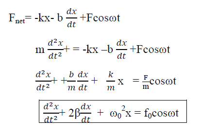
If an external periodic sinusoidal force Fcosωt acts on a damped oscillator, its equation of motion is written as,
 …………(1)
Where β= b/2m,  = k/m and f0 = F/m , and β and
  respectively called as damping coefficient, natural frequency.
Equation (1) is also represented as
 = f0cosωt
Equation (1) represents the general equation of forced oscillation.
Equation (1) is a non-homogenous differential equation with constant co-efficient. For weak damping ( >β 2) , the general equation contains,
x(t) = xc(t) + xp(t)
Where xc(t) is called complementary solution and its value is
 …………(2)
Now xp(t) is called the particular integral part.
Let us choose
xp(t) = P cos (ωt-δ)
 (t)= -Pωsin(ωt-δ)
 (t)=-Pω2cos(ωt-δ) ……………(3)
Putting xp(t) ,  (t),
(t), (t)in equation (1) we get


Now, comparing the coefficient of cos(ωt-δ) and sin (ωt-δ) on both sides,
( -ω2)P = f0cosδ……………(4)
2βPω = f0sinδ ……………(5)
Squaring and adding eqn (4) & (5)
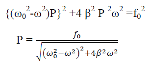
 ……….(6)
Now dividing equation (5) by (6)


This is steady state solution. Now
x(t) = xc(t) + xp(t)

STEADY STATE BEHAVIOUR
Frequency:-The Oscillator oscillates with the same frequency as that of the periodic force.
ω0and ω are very close to each other then beats will be produced and these beats are transient as it lasts as long as the steady state lasts. The duration between transient beats is determined by the damping coefficient β.
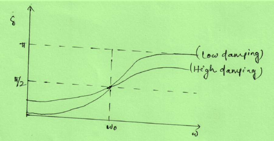
PHASE: The phase difference δ between the oscillator and the driving force or between the displacement and driving is

This shows that there is a delay between the action of the driving force and response of the oscillator.

Figure:8
(In the above figure fQ= ω0 and fp= ω)
At ω=ω0, φ =π/2, the displacement of the oscillator lags behind the driving force byπ/2.
At ω<<ω0 then δ=0→δ=0
For ω>>ω0 then δ =-2p/ω→ -0=π
AMPLITUDE: The amplitude of driven oscillator, in the steady state, is given by

It depends upon ( -ω2). If it is very small, then the amplitude of forced oscillation increases.
Case-1:At very high driving force i.eω>>ω0 and damping is small (β is small) or (β→0)
A = 
A =  =
= 
Amplitude is inversely proportional to the mass of the oscillator & hence the motion is mass controlled motion.
Case-2:At very low driving force (ω<<ω0) and damping is small (β→0),
i.e.  -ω2 =
-ω2 = 
A = 
A =  =
= 
So, when the low driving force is applied to oscillator, the amplitude remains almost constant for low damping. The amplitude of the forced oscillator in the region ω<<ω0and β<ω0 is inversely proportional to the stiffness constant (k) and hence motion is called the stiffness controlled motion.
Case:-3 (Resistance controlled motion)
When angular frequency of driving force=natural frequency of oscillator i.e.(ω=ω0)
A =  =
= 
A=f/bω=f/bω0
RESONANCE
Resonance occurs when:-
Frequency of the external periodic force = Natural frequency of the system.
Definition:-The phenomena of producing oscillatory motion in a system by the influence of an external periodic force having the same frequency as that of natural frequency of the system is called Resonance.
Example:- Resonance causes disaster during earthquake. When the natural frequency of the building becomes equal to the frequency of the periodic vibration present in the earth during earthquake, then the building starts vibrating with large amplitude and hence it collapses.
Sit in front of a piano sometime and sing a loud brief note at it with the dampers off its strings. It will sing the same note back at you—the strings, having the same frequencies as your voice, are resonating in response to the forces from the sound waves that you sent to them. Your voice and a piano’s strings is a good example of the fact that objects—in this case, piano strings—can be forced to oscillate but oscillate best at their natural frequency. In this section, we shall briefly explore applying a periodic driving force acting on a simple harmonic oscillator. The driving force puts energy into the system at a certain frequency, not necessarily the same as the natural frequency of the system. The natural frequency is the frequency at which a system would oscillate if there were no driving and no damping force.
Most of us have played with toys involving an object supported on an elastic band, something like the paddle ball suspended from a finger in Figure 9. Imagine the finger in the figure is your finger. At first you hold your finger steady, and the ball bounces up and down with a small amount of damping. If you move your finger up and down slowly, the ball will follow along without bouncing much on its own. As you increase the frequency at which you move your finger up and down, the ball will respond by oscillating with increasing amplitude. When you drive the ball at its natural frequency, the ball’s oscillations increase in amplitude with each oscillation for as long as you drive it.
The phenomenon of driving a system with a frequency equal to its natural frequency is called resonance. A system being driven at its natural frequency is said to resonate. As the driving frequency gets progressively higher than the resonant or natural frequency, the amplitude of the oscillations becomes smaller, until the oscillations nearly disappear and your finger simply moves up and down with little effect on the ball.
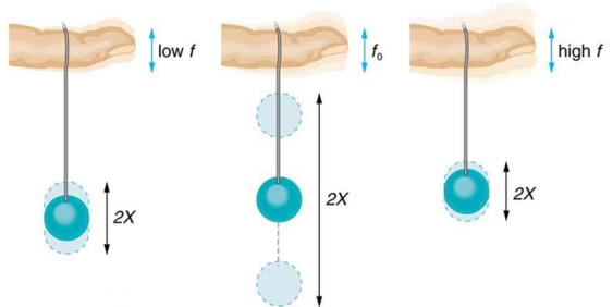
Figure 9: The paddle ball on its rubber band moves in response to the finger supporting it. If the finger moves with the natural frequency f0 of the ball on the rubber band, then a resonance is achieved, and the amplitude of the ball’s oscillations increases dramatically. At higher and lower driving frequencies, energy is transferred to the ball less efficiently, and it responds with lower-amplitude oscillations.
Figure10 shows a graph of the amplitude of a damped harmonic oscillator as a function of the frequency of the periodic force driving it. There are three curves on the graph, each representing a different amount of damping. All three curves peak at the point where the frequency of the driving force equals the natural frequency of the harmonic oscillator. The highest peak, or greatest response, is for the least amount of damping, because less energy is removed by the damping force.
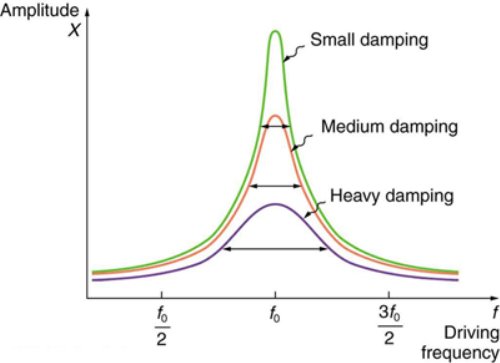
Figure10: Amplitude of a harmonic oscillator as a function of the frequency of the driving force. The curves represent the same oscillator with the same natural frequency but with different amounts of damping. Resonance occurs when the driving frequency equals the natural frequency, and the greatest response is for the least amount of damping. The narrowest response is also for the least damping.
It is interesting that the widths of the resonance curves shown in Figure 10 depend on damping: the less the damping, the narrower the resonance. The message is that if you want a driven oscillator to resonate at a very specific frequency, you need as little damping as possible. Little damping is the case for piano strings and many other musical instruments. Conversely, if you want small-amplitude oscillations, such as in a car’s suspension system, then you want heavy damping. Heavy damping reduces the amplitude, but the trade-off is that the system responds at more frequencies.
Many important physics systems involved coupled oscillators. Coupled oscillators are oscillators connected in such a way that energy can be transferred between them. The motion of coupled oscillators can be complex, and does not have to be periodic.
However, when the oscillators carry out complex motion, we can find a coordinate frame in which each oscillator oscillates with a very well defined frequency.
A solid is a good example of a system that can be described in terms of coupled oscillations. The atoms oscillate around their equilibrium positions, and the interaction between the atoms is responsible for the coupling.
Many physical systems require more than one variable to quantify their configuration; for example a circuit may have two connected current loops, so one needs to know what current is flowing in each loop at each moment.
Another example is a set of N coupled pendula each of which is a one-dimensional oscillator. A set of differential equations one for each variable will determine the dynamics of such a system.
For a system of N coupled 1-D oscillators there exist N normal modes in which all oscillators move with the same frequency and thus have fixed amplitude ratios (if each oscillator is allowed to move in x dimensions, then x N normal modes exist). The normal mode is for whole system.
Even though uncoupled angular frequencies of the oscillators are not the same, the effect of coupling is that all bodies can move with the same frequency. If the initial state of the system corresponds to motion in a normal mode then the oscillations continue in the normal mode.
However in general the motion is described by a linear combination of all the normal modes; since the differential equations are linear such a linear combination is also a solution to the coupled linear equations.
A normal mode of an oscillating system is the motion in which all parts of the system move sinusoidally with the same frequency and with a fixed phase relation.
The best way to illustrate the existence and nature of normal modes is to work through some examples, and to see what kind of motion is produced.

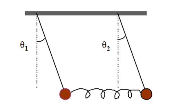
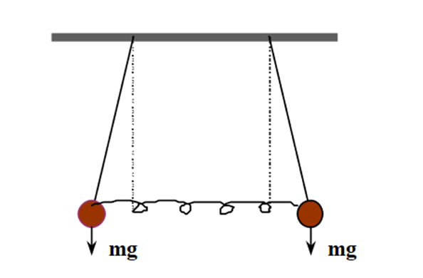
Figure 11: The Coupled Pendulum
We have two identical pendulums (length L) for which we consider small oscillations. In order to find what is the simplest motion, we imagine two experiments:
1) If we draw the two masses aside some distance and release them simultaneously from rest, they will swing in identical phase with no relative change in position. The spring will remain unstretched (or uncompressed) and will exert no force on either mass. We call this vibration pattern the first mode of vibration of the system.

Figure: 12
2) The other obvious way of starting a symmetric oscillation will be to stretch the spring from both ends. If we release the masses from rest simultaneously, we may notice that:
a)The spring now exerts forces during motion
b)From symmetry of motions of A and B, their positions are mirror images of each other

Figure:13
Rather than a single pendulum, now let us consider two pendula which are coupled together by a spring which is connected to the masses at the end of two thin strings. The spring has a spring constant of k and the length, l of each string is the same, as shown in Figure. 11
Unlike the simple pendulum with a single string and a single mass, we now have to define the equation of motion of the whole system together. However, we do this in exactly the same way as we would in any simple pendulum.
We first determine the forces acting on the first mass (left hand side). Like in the simple pendulum case, we assume that the displacements form the equilibrium positions are small enough that the restoring force due to gravity is approximately given by mgtanθ and acts along the line of masses. This force related to gravity produces the oscillatory motions if the pendulum is offset from the equilibrium position, i.e
 ………..(1)
Likewise, for the second mass
 ………..(2)
However, in addition to this gravitational force we also have the force due to the spring that is connected to the masses. This spring introduces additional forces on the two masses, with the force acting in the opposite direction to the direction of the displacement, if we assume that the spring obeys Hooke’s law. Therefore, the equations of motion become modified:
 ………..(3)
And
 ………..(4)
We now have two equations and two unknowns. To solve these equation by Decoupling Method
The first method is quick and easy, but can only be used in relatively symmetric systems ,e.g. where land mare the same, as in this case. The underlying strategy of this method is to combine the equations of motion given in Equation (3) and (4)in ways so that x and y only appear in unique combinations.
In this problem we can simply try adding the equations of motion, which is one of the two useful combinations that we will come across.
 ………..(5)
This type of equation should look familiar, where the left-hand side is a second derivative of the displacement with respect to time, and the right-hand side is a constant multi-plied by a displacement in x and y. It becomes more clear if we define
Equation (5) becomes,

This is now easily recognisable as the the usual SHM equation, with  = ω2q1where

Figure 14: The centre of mass motion of the coupled pendulum as described by q1=x+y.
Figure showing in phase mode..

We can then immediately write a solution for the system as
Where A1 andϕ1are arbitrary constants set by the initial or boundary conditions.
The motion described byq1=x+y tells us about the coupled motion of the two pendula in terms of how they oscillate together around a centre of mass. There is no dependence on the spring whatsoever, asω1does not have a term which involves k. This motion can be visualised as shown in
Given what we have learnt, the obvious other combination of x and y is to subtractEq. 3 from Eq. 4:

Now let us define

This gives us the following,

We have SHM again, but this time with theq2coordinate, with  = ω2q2, where in this case
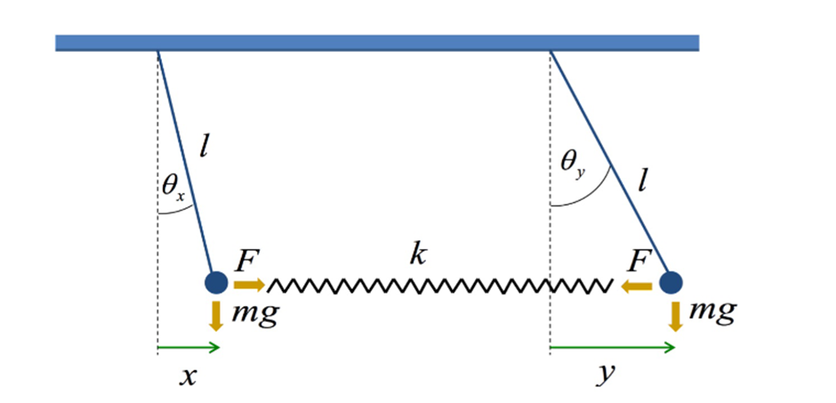
Figure 15: The relative motion of the coupled pendulum as described by q2 =x –y
Above Figure shows out of phase mode.
Again, we can write a solution immediately as
With A2 andϕ2 are arbitrary constants defined by the initial or boundary conditions.
In this case theq2represents the relative motion of the coupled pendulum. As should be clear from the dependence of ω2on the spring constant, this motion must describe how the motion of the system depends on the compression and expansion of the spring.
The variablesq1andq2are the modes or normal coordinates of the system. Inany normal mode, only one of these coordinates is active at any one time.
It is actually more common to define the normal coordinates with a normalising factor 1/ , such that
The factor of 1/ is chosen to give standard form for the kinetic enery in terms of the normal modes.
We now have the two normal modes that describe the system, and the general solution of the coupled pendulum is just the sum of these two normal modes.

which leads to,

And

which leads to,

The constant are then just set by the initial conditions.
INTRODUCTION TO WAVES
In physics a wave can be thought of as a disturbance or oscillation that travels through space-time accompanied by a transfer of energy. Wave motion transfers energy from one point to another, often with no permanent displacement of the particles of the medium —that is with little or no associated mass transport.
The emphasis of the last point highlights an important misconception of waves. Waves transfer energy not mass.
A wave is a vibratory disturbance in a medium which carries energy from one point to another point without any actual movement of the medium. There are three types of waves
There are two types of waves:

Figure: 16
Longitudinal Waves: A wave in which the particles of the medium vibrate back and forth in the ‘same direction’ in which the wave is moving. Medium can be solid, liquid or gases. Therefore, sound waves are longitudinal waves.These waves travel in the form of compressions and rarefactions.
Longitudinal waves have the same direction of vibration as their direction of travel. This means that the movement of the medium is in the same direction as the motion of the wave. Some longitudinal waves are also called compressional waves or compression waves. An easy experiment for observing longitudinal waves involves taking a Slinky and holding both ends. After compressing and releasing one end of the Slinky (while still holding onto the end), a pulse of more concentrated coils will travel to the end of the Slinky. In the example of the Slinky, each coil will oscillate at a point but will not travel the length of the Slinky. It is important to remember that energy, in this case in the form of a pulse, is being transmitted and not the displaced mass.
Longitudinal waves can sometimes also be conceptualized as pressure waves. The most common pressure wave is the sound wave. Sound waves are created by the compression of a medium usually air. Longitudinal sound waves are waves of alternating pressure deviations from the equilibrium pressure, causing local regions of compression and rarefaction. Matter in the medium is periodically displaced by a sound wave, and thus oscillates. When people make a sound, whether it is through speaking or hitting something, they are compressing the air particles to some significant amount. By doing so, they create transverse waves. When people hear sounds, their ears are sensitive to the pressure differences and interpret the waves as different tones.
Transverse Waves: A wave in which the particles of the medium vibrate up and down ‘at right angles’ to the direction in which the wave is moving. These waves are produced only in a solids and liquids but not in gases. These waves travel in the form of crests and troughs. If a transverse wave is moving in the positive x-direction, its oscillations are in up and down directions that lie in the y–z plane. Light is an example of a transverse wave. For transverse waves in matter, the displacement of the medium is perpendicular to the direction of propagation of the wave. A ripple on a pond and a wave on a string are easily visualized transverse waves.
Transverse waves are waves that are oscillating perpendicularly to the direction of propagation
CHARACTERISTICS OF WAVES
Wave can be described by following characteristics:
The distance between the centres of two consecutive compressions or two consecutive rarefactions is equal to its wavelength.
It is denoted by a Greek letter λ (lambda). The S.I unit for measuring wavelength is metre (m).

Figure 17: Wavelength of wave
The minimum distance in which a wave repeats itself is called its wavelength. That is it is the length of one complete wave. We know that in a sound wave, the combined length of a compression and an adjacent rarefaction is called its wavelength.
The distance between the centres of a compression and an adjacent rarefaction is equal to half of its wavelength i.e. λ/2.
When a wave passes through a medium, the particles of the medium get displaced temporarily from their original undisturbed positions and the maximum displacement of the particles of the medium from their original undisturbed positions is called amplitude of the wave.
The S.I unit of measurement of amplitude is metre (m) though sometimes it is also measured in centimetres.
Amplitude is used to describe the size of the wave. The amplitude of a wave is the same as the amplitude of the vibrating body producing the wave.
The time required to produce one complete wave or cycle is called time-period of the wave.
It is denoted by letter T. The unit of measurement of time-period is second (s).

Figure18 : Time period of wave
One complete wave is produced by one full vibration of the vibrating body. So, we can say that the time taken to complete one vibration is known as time-period
The number of complete waves or cycles produced in one second is called frequency of the wave.
The frequency of a wave is denoted by the letter f. The S.I unit of frequency is hertz written as Hz. Bigger unit of frequency is known as kilohertz (kHz). 1 kHz = 1000 Hz.

Figure 19: Frequency of sound wave
Since one complete wave is produced by one full vibration of the vibrating body so we can say that the number of vibrations per second is called frequency. A vibrating body emitting 1 wave per second is said to have a frequency of 1 hertz. That is 1Hz is equal to 1 vibration per second.
Frequency of a wave is fixed and does not change even when it passes through different substances. The frequency of a wave is the same as the frequency of the vibrating body which produces the wave.
For example: if 20 complete waves or vibrations are produced in one second then the frequency of the waves will be 20 hertz or 20 cycles per second.
What is the relation between time-period and frequency of a wave?
The time required to produce one complete wave is called time-period of the wave. Suppose the time-period of a wave is T seconds.
In T seconds number of waves produced = 1
So, in 1 second, number of waves produced will be = 1/T
But the number of waves produced in 1 second is called its frequency.
Therefore, F = 1/Time-period
f = 1/T
where f = frequency of the wave
T = time-period of the wave
The distance travelled by a wave in one second is called velocity of the wave or speed of the wave.
It is represented by the letter v. The S.I unit for measuring the velocity is metres per second (m/s or ms-1).
What is the relationship between Velocity, Frequency and Wavelength of a Wave?
Velocity = Distance travelled/ Time taken
Let v = λ / T
Where T = time taken by one wave.
v = f Xλ
This formula is known as wave equation.
Where v = velocity of the wave
f = frequency
λ = wavelength
Velocity of a wave = Frequency X Wavelength
This applies to all the waves like transverse waves like water waves, longitudinal waves like sound waves and the electromagnetic waves like light waves and radio waves
WAVE EQUATION
We apply Newton’s law to an elastic string, concluding that small amplitude transverse vibrations of the string obey the wave equation. Consider a tiny element of the string.

Figure:20
The basic notation is
u(x, t) = vertical displacement of the string from the x axis at position x and time t
θ(x, t) = angle between the string and a horizontal line at position x and time t
T(x, t) = tension in the string at position x and time t
ρ(x) = mass density of the string at position x
The forces acting on the tiny element of string are
(a) Tension pulling to the right, which has magnitude T(x+ ∆x, t) and acts at an angle θ(x+ ∆x, t) above horizontal
(b) Tension pulling to the left, which has magnitude T(x, t) and acts at an angle θ(x, t) below horizontal and, possibly,
(c) Various external forces, like gravity. We shall assume that all of the external forces act vertically and we shall denote by F(x, t)∆x the net magnitude of the external force acting on the element of string. The mass of the element of string is essentially.
The mass of the element of string is essentially ρ(x) so the vertical component of Newton’s law says that

Dividing by ∆x and taking the limit as ∆x→0 gives

…………(1)
We can dispose of all the θ’s by observing from the figure that

which implies, using the figure on the right below, that

Substituting these formulae into (1) give a horrendous mess. However, we can get considerable simplification by looking only at small vibrations. By a small vibration, we mean that |θ(x, t)| ≪1 for all x and t. This implies that |tanθ(x, t)| ≪1, hence that ∣∣∂u/∂x(x, t)∣∣≪1 and hence that

…………(2)
Substituting these into equation (1) give

…………(3)
which is indeed relatively simple, but still exhibits a problem. This is one equation in the two unknowns u and T.
Fortunately there is a second equation lurking in the background, that we haven’t used. Namely, the horizontal component of Newton’s law of motion. As a second simplification, we assume that there are only transverse vibrations. Our tiny string element moves only vertically. Then the net horizontal force on it must be zero. That is,

Dividing by ∆x and taking the limit as ∆x tends to zero gives

For small amplitude vibrations, cosθ is very close to one and ∂T/∂x(x, t) is very close to zero. In other words T is a function of t only, which is determined by how hard you are pulling on the ends of the string at time t. So for small, transverse vibrations, (3) simplifies further to

…………(4)
In the event that the string density ρ is a constant, independent of x, the string tension T(t) is a constant independent of t(in other words you are not continually playing with the tuning pegs) and there are no external forces F we end up with

Where
C = 
The reflection of sound follows the law "angle of incidence equals angle of reflection", sometimes called the law of reflection. The same behaviour is observed with light and other waves, and by the bounce of a billiard ball off the bank of a table. The reflected waves can interfere with incident waves, producing patterns of constructive and destructive interference. This can lead to resonances called standing waves in rooms. It also means that the sound intensity near a hard surface is enhanced because the reflected wave adds to the incident wave, giving a pressure amplitude that is twice as great in a thin "pressure zone" near the surface. This is used in pressure zone microphones to increase sensitivity. The doubling of pressure gives a 6 decibel increase in the signal picked up by the microphone. Reflection of waves in strings and air columns are essential to the production of resonant standing waves in those systems.
The phase of the reflected sound waves from hard surfaces and the reflection of string waves from their ends determines whether the interference of the reflected and incident waves will be constructive or destructive. For string waves at the ends of strings there is a reversal of phase and it plays an important role in producing resonance in strings. Since the reflected wave and the incident wave add to each other while moving in opposite directions, the appearance of propagation is lost and the resulting vibration is called a standing wave.
When sound waves in air (pressure waves) encounter a hard surface, there is no phase change upon reflection. That is, when the high pressure part of a sound wave hits the wall, it will be reflected as a high pressure, not a reversed phase which would be a low pressure. Keep in mind that when we talk about the pressure associated with a sound wave, a positive or "high" pressure is one that is above the ambient atmospheric pressure and a negative or "low" pressure is just one that is below atmospheric pressure. A wall is described as having a higher "acoustic impedance" than the air, and when a wave encounters a medium of higher acoustic impedance there is no phase change upon reflection.
On the other hand, if a sound wave in a solid strikes an air boundary, the pressure wave which reflects back into the solid from the air boundary will experience a phase reversal - a high-pressure part reflecting as a low-pressure region. That is, reflections off a lower impedance medium will be reversed in phase.
Consider two halfspaces (deep ocean on top of earth, for example). If a wave of unit amplitude is incident onto the boundary, there is a transmitted wave of amplitude t and a reflected wave of amplitude c as depicted in Figure 21.

Figure 21: Waves incident, reflected c, and transmitted t at an interface.
A very simple relationship exists between t and c. The wave amplitudes have a physical meaning of something like pressure, material displacement, traction, or tangential electric or magnetic fields. These physical variables must be the same value on either side of the boundary. This means the transmitted wave must equal the sum of the incident plus reflected waves.
| (1) | |
| (2) |
The reflection coefficientc may be positive or negative so the transmission coefficientt may be greater than unity. It may seem surprising that t can be greater than unity. This does not violate any physical laws. At the seashore we see waves approaching the shore and they get larger as they arrive. Energy is not determined by wave height alone. Energy is equal to the squared wave amplitude multiplied by a proportionality factor Y depending upon the medium in which the wave is measured. If we denote the factor of the top medium by Y1 and the bottom by Y2, then the statement that the energy before incidence equals the energy after incidence is
| | (3) |
solving for c leads us to
|
| |
|
| |
|
| |
| (4) |
In acoustics the up- and downgoing wave variables may be normalized to either pressure or velocity. When they measure velocity, the scale factor multiplying velocity squared is called the impedanceI. When they measure pressure, the scale factor is called the admittanceY.
The wave c' which reflects when energy is incident from the other side is obtained from (4) if Y1 and Y2 are interchanged. Thus
| | (5) |
A perfectly reflecting interface is one which does not allow energy through. This comes about not only when t = 0 or c = -1, but also when t = 2 or c = +1. To see this, note that on the left in Figure 21
|
| |
| (6) |
Equation (6) says that 100 percent of the incident energy is transmitted when Y1 = Y2, but the percentage of transmission is very small when Y1 and Y2 are very different.
Ordinarily there are two kinds of variables used to describe waves, and both of these can be continuous at a material discontinuity. One is a scalar like pressure, tension, voltage, potential, stress, or temperature. The other is a vector which we use the vertical component. Examples of the latter are velocity, stretch, electric current, displacement, and heat flow. Occasionally a wave variable is a tensor. When a boundary condition is the vanishing of one of the motion components, then the boundary is often said to be rigid. When it is the pressure or potential which vanishes, then the boundary is often said to be free. Rigid and free boundaries reflect waves with unit magnitude reflection coefficients.


