Module 1
DC & AC Circuits
Ohm's Law
Ohm's law is the relationship between voltage, current, and resistance in a circuit. Ohm's law can be written which is commonly used.
Kirchhoff Voltage Law:
A loop is a path around a circuit that starts and ends in the same place.
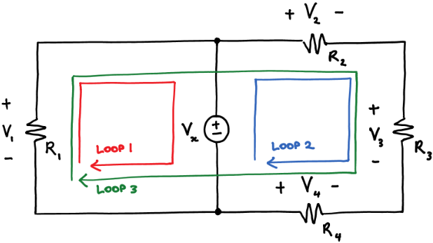
Kirchhoff's voltage law (KVL) states that around a loop:
sum of voltage rises=sum of voltage drops--------------------(1)
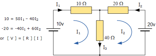
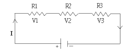
Applying KVL around the three loops we get
V1 = Vx KVL around loop 1
Vx + V4 = V2 + V3 KVL around loop2
V1 + V4 = V2 + V3 KVL around loop3
Kirchhoff Current Law:
A node is a circuit connection that extends to all its neighboring elements but does not contain them.
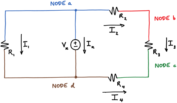
Kirchhoff’s current law states that at a node:
Sum of the in currents = sum of out currents
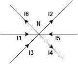
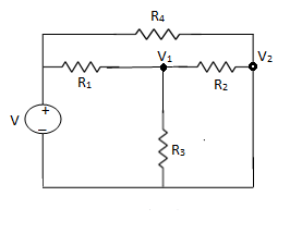
Applying KCL at four nodes
0 = Ix + I1 + I2 KCL at node a
I2 = I3 KCL at node b
I3 + I4 = 0 KCL at node c
Ix + I1 = I4 KCL at node d
Adding equations 6-9 gives the following equation:
Ix + I1 + I2 + I3 + I4 = Ix + I1 + I2 + I3 + I4.
1.1.1 Fundamentals of electrical circuit
Charge:
An electron carries a negative charge of 1.602 x 10⁻¹⁹ C. where the unit of charge is the Coulomb (C).
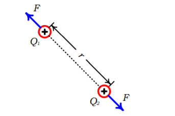
Charges of the same sign repel each other, while charges of opposite sign attract.
For example, consider two point charges, Q1 and Q2, separated a distance r as shown in Figure.
The force exerted by one charge on the other varies directly as the product of the charges and inversely as the square of the distance between them according to Coulomb’s law:
F = k Q1 Q / r 2
The constant of proportionality, k, is approximately 9x10⁹ when the other parameters are given in SI units and the surrounding medium is free space.
Voltage:
Since charges exert forces on other charges, energy must be expended in moving a charge in the vicinity of other charges. Thus, charges produce a type of force field.
The unit of energy is the joule (J), defined as the energy expended in the exertion of ta force of one Newton in moving an object through a distance of one meter (1J = Nm
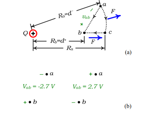
For example, consider moving a charge q from point a to point b along a chosen path in the presence of another charge Q as illustrated in Fig.
The movement of q from a to b as in Fig. requires work wba on our part then we say that the voltage of point b with respect to point a is the work per unit charge required to move the charge from point a to point b:
V ba = w ba / q -------------------------------(1)
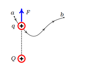
Alternatively, we say that there is a potential difference between points a and b with point b at an assumed higher potential. If this is negative number, it means a is at higher potential.
Determining the voltage between two points that is established by point charge Q is a simple matter as shown by the following example.
Example :
A charge Q establishes a voltage between points a and b as shown in Fig. The two points are at radial distances Ra and Rb from the point charge. Determine the voltage Vbc between the two points (point b at the assumed higher potential).
Solution:
Energy required to move a test charge q from a to b is :
Wba = -  x 10 9 qQ/ r 2 d R = 9 x 10 9 Qq( 1/Rb – 1/Ra) V
Hence the voltage point b with respect to a is given by
Vba = wba / q = 9 x 10 9 Q( 1/Rb – 1/Ra ) V
Vba = wba / q = 9 x 10 9 Q( 1/d+ - 1/d-) V
As an example, suppose that Q is a negative charge,
Q=-1x10⁻⁹ C, and Ra =5 m and Rb = 2 m. The resulting voltage of point b with respect to point a is vba=-2.7 V.
This indicates that point a is at the higher potential than point b by 2.7 V. This is a sensible result in that Q being negative actually provides an attractive force for the movement of q from a to b.
Hence, we could denote the voltage between the two points in either of two equivalent ways as shown in Fig.
Current:
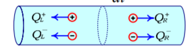
Current is the rate of movement of electric charge. If we observe the charge crossing an area of the cylinder in a certain time interval, ∆t, then the current directed to the right is defined as the net positive charge transferred to the right per unit of time:
i = ∆Q / ∆t
The unit of current is the Ampere (A), defined as the movement of one coulomb of net positive charge past a point in one second (1 A=1 C/s) This rate of movement may not be constant but may vary with time. Hence the general definition of current is:
i(t) = d Q(t) /dt
Consider the plot of net positive charge moving past a point shown in Fig. Over the time interval 1 s ≤ t ≤ 3 s the net positive charge passing to the right is increasing at a rate of 1C/s, and 1 A of current results. Over 3 s ≤ t ≤ 5 s the net positive charge passing to the right is decreasing at a rate of -1.5C/s and hence the current at any point in this time interval is -1.5A.
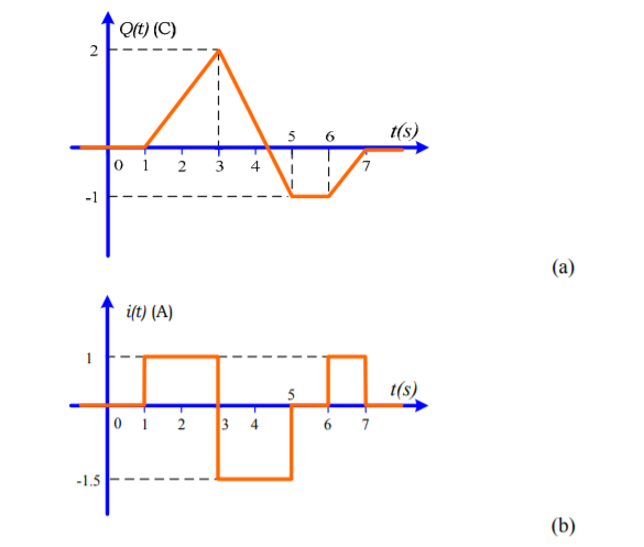
Conversely, the net positive charge passing a point is:
Q(t) =  d
d 
so that the net positive charge passing the point between two times is:
Q(t2) – Q(t1) =  d
d 
This Equation can be interpreted as the total area under the current -versus-time curve from the beginning of time to the present time.
1.1.2 Ohm’s law
Ohm’s Law states that the current flowing through a conductor is directly proportional to the potential difference applied across its ends, provided the temperature and other physical conditions remain unchanged. Mathematically it can be represented as,
Potential difference ∝ Current
V ∝ I
( When the value of V increases the value of I increases simultaneously)
V = IR
Where,
V is Voltage in volts (V)
R is Resistance in ohm (Ω)
I is Current in Ampere (A)
The main applications of Ohm’s law are:
1.1.3 Kirchoff’s laws
The algebraic sum of currents meeting at a junction or node in a electric circuit is zero or the summation of all incoming current is always equal to summation of all outgoing current in an electrical network.
Explanation
Assuming the incoming current to be positive and outgoing current negative we have


I e incoming current = ∑ outgoing current thus, the above Law can also be stated as the sum of current flowing towards any junction in an electric circuit is equal to the sum of currents flowing away from that junction
Kirchhoff’s Voltage Law (KVL)
statement : the algebraic summation of all Voltage in any closed circuit or mesh of loop zero.
ie ∑ Voltage in closed loop = 0 the summation of the Voltage rise (voltage sources) is equal to summation of the voltage drops around a closed loop in 0 circuit for explanation from here
determination of sigh and direction of currents (Don’t write in exams just for understanding)
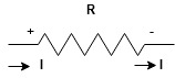
current entering a resistor is +ve and leaving should be –ve
now
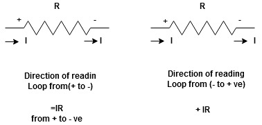


Potential Rise Potential Drop
We are reading from +V to –V we are reading from –V to +V
 potential drops
  potential rise
 -V
-V  +V
+V
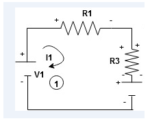
Given Circuit
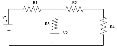
First identify no of loops and assign direction of current flowing in loop
Note : no of loops in circuit = No, of unknown currents = no, of equations in the circuit
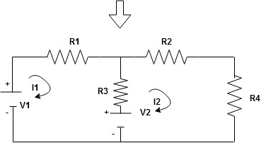
Note : keep loop direction and current direction same ie either clockwise or anticlockwise for all loops I1 I2
Now according to direction of direction assign signs (+ve to –ve) to the resistors
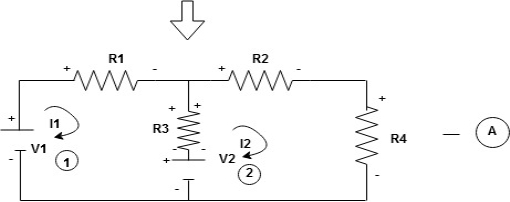
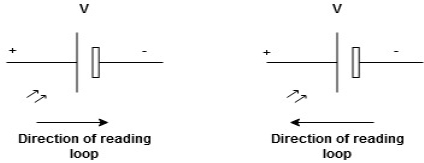
Note : voltage sources (V) polarities does not change is constant.
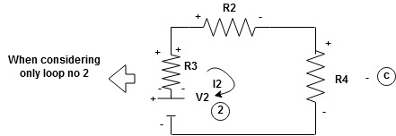
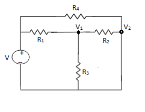
Note: for common resistor between 2 loops appearing in the circuit like R3 give signs according to separate loops as shown

When considering only loop no 1 (+ R3 - )
B
Now consider diagram A and write equations
Two loops  two unknown currents
  two equation
Apply KVL for loop ① [B. Diagram ]
(+ to drop -) = - sign and (- to rise +) = + sign
 for drop = -sign
 for rise = + sign
-
-( ) R2 is considered because in R3,2 currents are flowing
  and
and  and we have taken (
 ) because we are considering loop no 1 and current flowing is
  in loop no 1
 )
)
Similarly for loop no. 2 currents flowing is 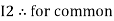 resistor R3 it should be
  )R3
)R3
Consider loop no. 1 apply KVL
- …….①
…….①
-
Consider loop no. 2 apply KVL
- …….②
…….②
-
After solving equation ① and ② we will get branch current  and
and 
1.1.3 Series and parallel connections
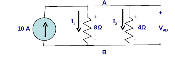
Parallel connection:

Using KVL we get
- I1 . 8 Ω + I2 . 4 Ω =0
Solving we get
I2 = 2 I1
Using KCL we get
I1 + I2 = 10
I1 + 2I1 = 10
3I1 = 10
I1 = 3.33 A
I2 = 6.67 A
VAB = 26.33 volts

In the above circuit the resistors R1 , R2 and R3 are connected in series across the voltage source V1 , V2 , V3 and voltage drops across the resistors R1, R2 , R3 . According to KVL
V + (-V1 ) + (-V2) + (-V3 ) = 0
V – V1 – V2 – V3 =0
V = V1 + V2 + V3
This is called KVL equation that is the applied voltage equals sum of all voltage drops.
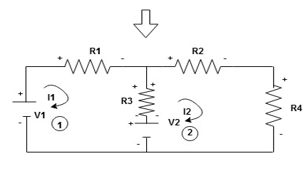
1.1.5 Analysis of circuits using Node voltage
NODE ANALYSIS
For these we assume every node as a voltage point and write the current equation for every element. For current source, current entering is negative.
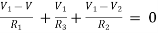
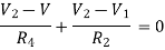
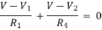
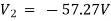
For node V1
For node V2
For V
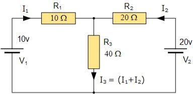
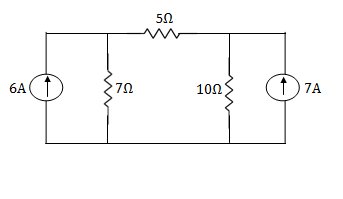
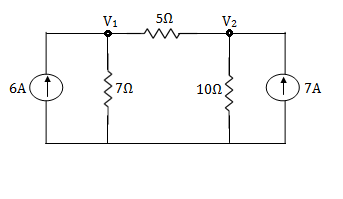
Example: Using nodal analysis find voltage across 5resistor.
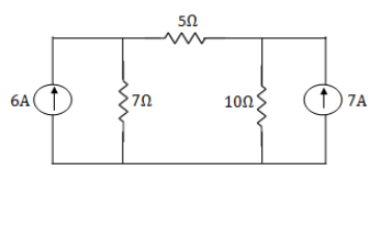
Solution:
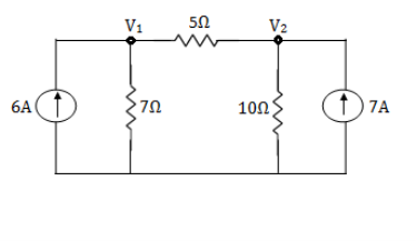
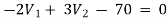
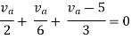
For V1
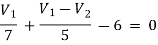
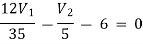
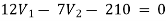 -1
-1
For V2
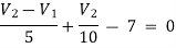
 -2
-2
Solving 1 and 2:

For 5 voltage = 
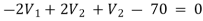
= -50.9 + 57.27
= 6.37V
1.1.6 Mesh current
Mesh Current Analysis
An easier method of solving the above circuit is by using Mesh Current Analysis or Loop Analysis which is also sometimes called Maxwell´s Circulating Currents method.
Instead of labelling the branch currents we need to label each “closed loop” with a circulating current.
Any required branch current may be found from the appropriate loop or mesh currents as before using Kirchhoff´s method.
For example: : i1 = I1 , i2 = -I2 and I3 = I1 – I2
Therefore,
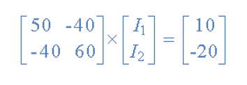
These equations can be solved quite quickly by using a single mesh impedance matrix Z. Each element ON the principal diagonal will be “positive” and is the total impedance of each mesh. Where as, each element OFF the principal diagonal will either be “zero” or “negative” and represents the circuit element connecting all the appropriate meshes.
[ V] = [I] x [R] or [R] x [I] = [V]
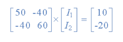
I = V/R = R-1 x V
Inverse of R = [ 60 40
40 50 ]
|R| = (60 x 50 ) – (40 x 40 ) = 1400
R – 1 = 1/1400 [ 60 40
40 50]
having found the inverse of R, as V/R is the same as V x R-1, we can now use it to find the two circulating currents.
[I] = [ R -1] x [V]
[ I1]= 1/1400 [ 60 40 [10]
[I2 ] = 40 50 ] x [ -20]
I1 = (60 x 10 ) + (40 x -20 ) /1400 = -200/1400 = -0.143 A
I2 = (40 x 10 ) + (50 x -20) /1400 = -600/1400 = -0.429A
Where:
and this gives I1 as -0.143 Amps and I2 as -0.429 Amps
As : I3 = I1 – I2
The combined current of I3 is therefore given as : -0.143 – (-0.429) = 0.286 Amps
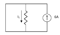
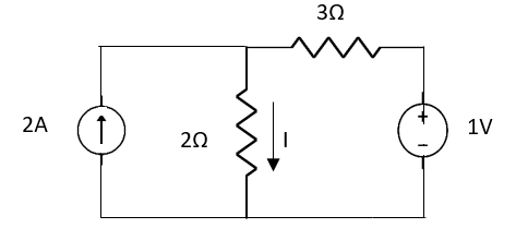
1.1.7 Superposition
Superposition Theorem
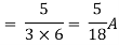
Question 1. Find the current through  resistance.
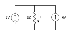
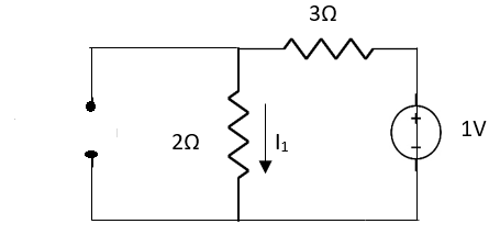
Solution:
 1= 0
1= 0
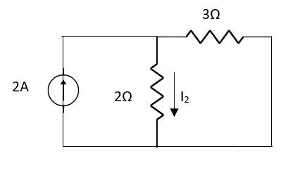
 2=
2=
 1 +
1 +  2
2 
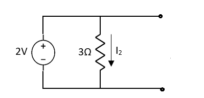
Special Case:
Since two voltage sources with different magnitude in parallel which cannot be connected as in single branch two different current is not possible (if 5V than I = zero).
Question:

 1 =
1 = 
 2 =
2 = 
=
 1 +
1 +  2
2
= 
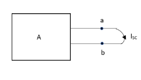
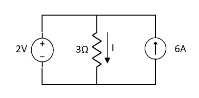
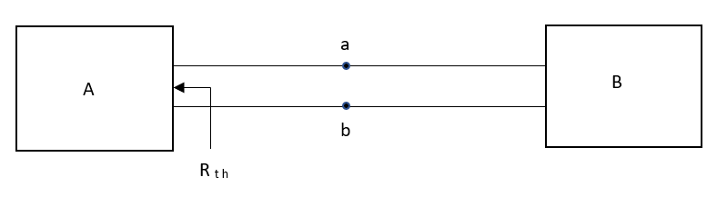
1.1.8 Thevenin and Norton Theorems to solve simple circuits with dc excitation
Thevenin’s and Norton’s Theorem
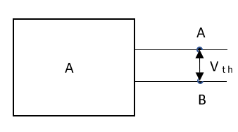
Thevenin’s equivalent of A
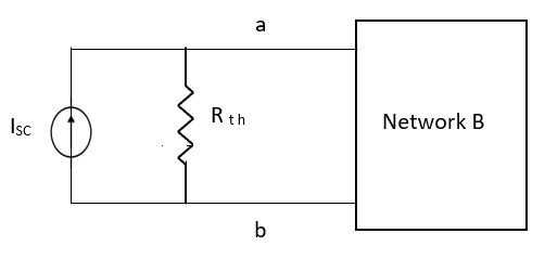
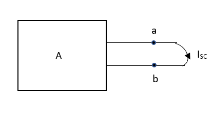
Norton’s equivalent of A
 sc = Vth/Rth
CONDITIONS FOR APPLICATION
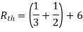
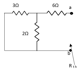
Method for finding Rth :
Firstly, open circuit terminal A and B.
2. If network A is operating with independent and dependent sources:
3. If network is operating with only dependent sources:
Connect generation between A and B

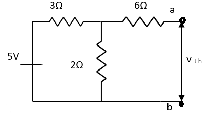
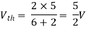
Method for Vth:
First open circuit terminal A and B.
Find out the voltage between A and B this is Vth
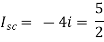
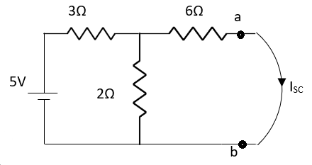
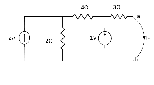
Method for Isc:

Question:
Answer:


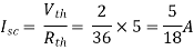
Finding Isc from circuit directly:
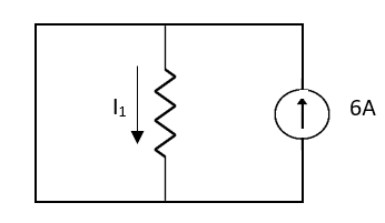
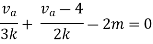
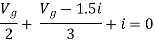
By KCL,


Question:
Answer
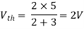
Also, clear from circuit that Vth = 1V.
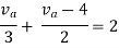
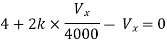
By applying KVL we get,
1-3Isc=0
Isc= A
A
Que:
Ans;
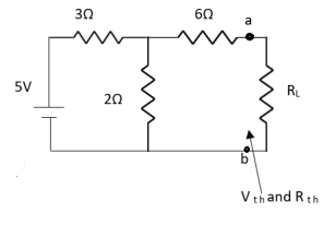
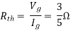
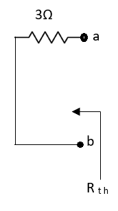
Rth=3k+2k=5k
By applying KVL we get


Therefore, 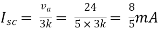
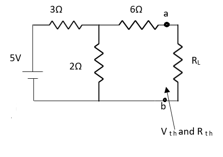
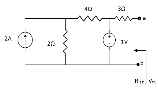
Question:

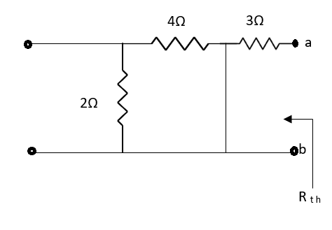
Solution: For Rth
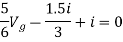
By KCL,
But, 


By KVL,


Question:
Solution: Since, no independent source is present so,
Isc = 0
And we know that,


Since Rth cannot be zero

But 

Question: Find out the Norton’s equivalent
Solution:

Since, there is no significance of current source


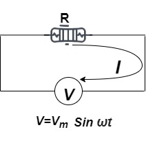
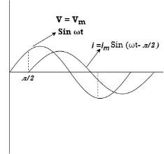
A purely or a non-inductive circuit which has inductance so small that at normal frequency its reactance is negligible compared to its resistance. If the circuit is purely non-inductive no reactance emf is set up and whole of the applied voltage is utilized in overcoming the ohmic resistance of the circuit.
The current flowing through a pure resistance changes, no back emf is set up, therefore, applied voltage overcomes the ohmic drop of i R only:
i.e i R = v
i = v/R = Vmax/R sin wt
current will be maximum when wt = π/2 or sinwt =1
Imax = Vmax/R
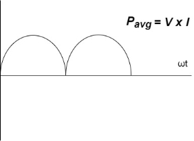
and instantaneous current may be expressed as:
i = Imax sin ωt
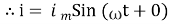
From the expressions of instantaneous applied voltage and instantaneous current, it is evident that in a pure resistive circuit, the applied voltage and current are in phase with each other, as shown by wave and phasor diagrams in (b) and (c) respectively.
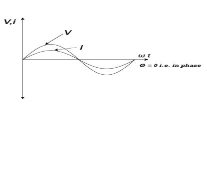
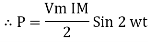
The instantaneous power delivered to the circuit in question is the product of the instantaneous values of applied voltage and current.
i.e p = v i = Vmax sin wt . I max sin wt = Vmax I max sin 2 wt
p = Vmax . Imax / 2 (1 -cos 2 wt) sin 2 wt = 1 – cos 2 wt/2
p = Vmax I max /2 (1 – cos 2 wt)
= Vmax I max /2 - Vmax Imax /2 cos 2 wt
Average Power = Vmax I max / 2 – average of Vmax . I max /2 cos 2 wt
Since average of Vmax I max/2 cos 2wt over a complete cycle is zero
P = Vmax . I max/2 = Vmax /  . I max /
  = VI watts
Where V and I are the rms values of applied voltage and current respectively.
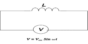
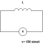
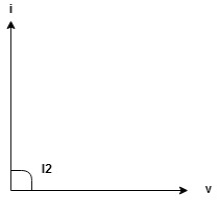
Purely inductive circuit.
An inductive circuit is a coil with or without an iron core having negligible resistance.
When an alternating voltage is applied to purely inductive coil an emf known as self-induced emf is induced in the coil which opposes the applied voltage. Since the coil has no resistance at every instant of the applied voltage has to overcome this self-induced emf only.
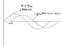
Let the applied voltage v = Vmax sin wt
And self- inductance of coil = L henry
Self- induced emf in the coil eL = - L di/dt
Since the applied voltage at every instant is equal and opposite to the self induced emf
v = - eL
Vmax sin wt = -(-L di/dt)
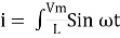
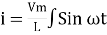
di = Vmax/ L sin wt dt
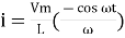
Integrating both sides we ger
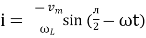
i = Vmax/L  = Vmax / wL sin (wt – π/2)
current will be maximum when sin(wt – π/2) = 1 hence maximum value of current
I max = Vmax / wL
And the instantaneous current is expressed as
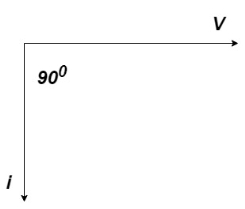
i = I max sin (wt – π/2)
Purely inductive circuit
ωL in the expression Imax = Vmax/ωL is known as inductive reactance and is denoted by XL i.e., XL = ω L
If L is in henry and co is in radians per second then XL will be in ohms.
Power in Purely Inductive Circuit:
Instantaneous power, p = v × i = Vmax sin ω t Imax sin (ωt – π/2)
Or p = – Vmax Imax sin ω t cos ω t = Vmax Imax/2 sin 2 ωt
The power measured by wattmeter is the average value of p which is zero since average of a sinusoidal quantity of double frequency over a complete cycle is zero. Hence in a purely inductive circuit power absorbed is zero
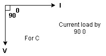
Capacitive:
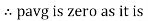
The charging current will flow only during the period of “build up” and will cease to flow as soon as the capacitor has attained the steady voltage of the source. This implies that for a direct current, a capacitor is a break in the circuit or an infinitely high resistance.
During the first quarter-cycle, the applied voltage increases to the peak value, and the capacitor is charged to that value. The current is maximum in the beginning of the cycle and becomes zero at the maximum value of the applied voltage, so there is a phase difference of 90° between the applied voltage and current. During the first quarter-cycle the current flows in the normal direction through the circuit; hence the current is positive.
In the second quarter-cycle, the voltage applied across the capacitor falls, the capacitor loses its charge, and current flows through it against the applied voltage because the capacitor discharges into the circuit. Thus, the current is negative during the second quarter-cycle and attains a maximum value when the applied voltage is zero.
The third and fourth quarter-cycles repeat the events of the first and second, respectively, with the difference that the polarity of the applied voltage is reversed, and there are corresponding current changes.
In other words, an alternating current flows in the circuit because of the charging and discharging of the capacitor. As illustrated in Figs.(b) and (c) the current begins its cycle 90 degrees ahead of the voltage, so the current in a capacitor leads the applied voltage by 90 degrees – the opposite of the inductance current-voltage relationship.
Let an alternating voltage represented by v = Vmax sin ω t be applied across a capacitor of capacitance C farads.
The expression for instantaneous charge is given as:
q = C Vmax sin ωt
Since the capacitor current is equal to the rate of change of charge, the capacitor current may be obtained by differentiating the above equation:
i = dq/dt = [ C Vmax sin wt] = w C Vmax cos wt = V max / 1/wC sin (wt + π/2)
Current is maximum when t=0.
Imax = Vmax / 1/wC
i = Imax sin (wt + π/2)
From the equations of instantaneous applied voltage and instantaneous current flowing through capacitance, it is observed that the current leads the applied voltage by π/2, as shown in Figs. (b) and (c) by wave and phasor diagrams respectively.
Capacitive Reactance:
1/ω C in the expression Imax = Vmax/1/ω C is known as capacitive reactance and is denoted by XC i.e., XC = 1/ω C
If C is in farads and ω is in radians/s, then Xc will be in ohms.
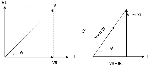
Power in Purely Capacitive Circuit:
p = v I = Vmax sin wt . I max sin (wt + π/2)
= Vmax . I max/2 x average of sin 2 wt
Over complete cycle =0
Hence power absorbed in a purely capacitive circuit is zero. The same is shown graphically in Fig. (b). The energy taken from the supply circuit is stored in the capacitor during the first quarter- cycle and returned during the next.
The energy stored by a capacitor at maximum voltage across its plates is given by the expression:
Wc = ½ C V2 max.
1.2.1 Single phase emf generation
Single phase EMF generation:
Alternating voltage may be generated
1) By rotating a coil in a magnetic field
2) By rotating a magnetic field within a stationary coil .
The value of voltage generated depends upon
1) No. of turns in the coil
2) field strength
3) speed Equation of alternating voltage and current
N= No. of turns in a coil
Φm= Maximum flux when coil coincides with X-axis
ω= angular speed (rad/sec) = 2πf
At θ=ωt, Φ= flux component ⊥ to the plane =Φm cos ωt
According to the Faraday’s law of electromagnetic induction,
e -N dɸ/dt = - N d/dt ɸm cos wt = w N ɸm sin wt ----------------------------(1)
When e is maximum value of Em when sin Ɵ = sin 90 = 1
Ie Em = w N ɸm -----------------------------------------------------------------------(2)
From equation (1) and (2)
e = Em sin wt volt
Now current (i) at any time in the coil is proportional to the induced emf€ in the coil.
Hence i = Im sin wt amp
1.2.2 Representation of sinusoidal waveforms, average, effective, peak and rms values, j operator
Cycle:
Each repetition of set of positive and negative Instantaneous value of an alternating quantity is called as cycle.
Time period:
The time taken by an alternating quantity to complete its on cycle known as time period.
Frequency:
The numbers of cycle completed by an alternating quantity per second known as Frequency.Measured in cycle/second or that.
Angular Frequency (w):
It is the Frequency expressed in electrical radians per second w = 2 X F or w = 
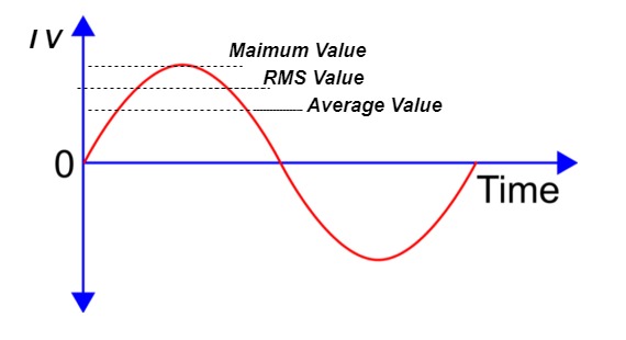
Instantaneous value:
The value of an alternating quantity at a particular instant is known as Instantaneous value.
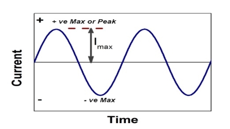
Peat to peak value:
The value of an alternating quantity from its positive peak to negative peak
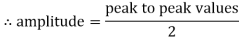
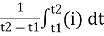
Average Value:
The arithmetic mean of all the value over complete one cycle is called as average value
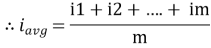
 =
= 
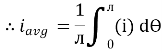
For the derivation we are considering only hall cycle.
Thus  varies from 0 to ᴫ
i = Im Sin
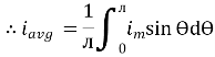
Solving
We get

Similarly, Vavg=
The average value of sinusoid ally varying alternating current is 0.636 times maximum value of alternating current.
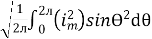
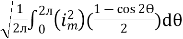
RMS value: Root mean square value
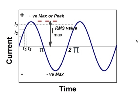
The RMS value of AC current is equal to the steady state DC current that required to produce the same amount of heat produced by ac current provided that resistance and time for which these currents flows are identical.
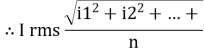
I rms = 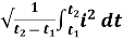
Direction for RMS value:
Instantaneous current equation is given by
i = Im Sin 
but 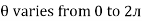
I rms = 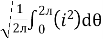
= 
=
=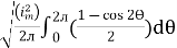
Solving
=
=
Similar we can derive
V rms=  or 0.707 Vm
 the RMS value of sinusoidally alternating current is 0.707 times the maximum value of alternating current.
Peak or krest factor (kp) (for numerical)
It is the ratio of maximum value to rms value of given alternating quantity
Kp = 
 Kp =
Kp = 
 Kp = 1.414
Form factor (Kf): For numerical “It is the ratio of RMS value to average value of given alternating quality”.

1.2.3 Rectangular and polar representation of phasors
The instantaneous voltage equation is given by
Vt= vm sin (w t +Ø)
which can be represented by polar form
vt =  L Ø
L Ø
where  = peak value
e.g. vt =30 sin (w t + 90 )
)
polar form  < 90
< 90
polar form is suitable for multiplication and division of phases.
2. Rectangular Form:
The instantaneous voltage equation is given by
Vt = v m sin (w t +Ø)
which can be represented by Rectangular Form
vt = 
where X =  or Vm cos Ø
Y = or Vm sin Ø
Vt = v m cos Ø + i vm sin Ø
e.g. 30 sin (w t + 90)
Rectangular form vt = 30 cos 90 + i 30 sin 90
 Rectangular Form is suitable for addition and subtraction of Phases.
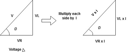
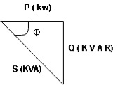
1.2.4 Real power
Real power/ True power/Active power/Useful power : (P) it is defined as the product of rms value of voltage and current and the active component or it is the average or actual power consumed by the resistive path (R) in the given combinational circuit.
It is measured in watts
P = VI  Φ watts / KW, where Φ is the power factor angle.
1.2.5 Reactive power
Reactive power/Imaginary/useless power [Q]
It is defined as the product of voltage, current and sine B and I
Therefore,
Q= V.I  Φ
Φ
Unit –V A R
In kilo- KVAR
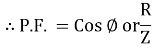
As we know power factor is cosine of angle between voltage and current
i.e. Φ.F= CosΦ
In other words also we can derive it from impedance triangle
Now consider Impedance triangle in R.L.ckt
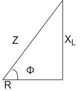
From triangle ,
Now  Φ – power factor=
Power factor =  Φ or
Φ or 
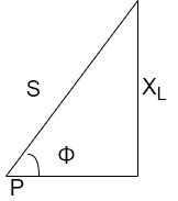
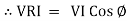
1.2.6 Apparent power
S= V × I
Unit - Volte- Ampere (VA)
In kilo – KVA
1.2.7 Power factor
It is denoted by “PF” and is equal to the cosine function of the phase ɸ between voltage and current vectors in sinusoidal voltage. It is also the ratio of Active Power (P) in watts to Apparent power in VA. The maximum value is 1. It ranges from 0.6 to 0.8
1.2.8 Analysis of single-phase ac circuits consisting of R, L, C, RL, RC, RLC combinations (series and parallel).
3 Basic element of AC circuit.
1] Resistance
2] Inductance
3] Capacitance
Each element produces opposition to the flow of AC supply in forward manner.
Reactance
It is opposition to the flow of an AC current offered by inductor.
XL = ω L But ω = 2 ᴫ F
 XL = 2 ᴫ F L
It is measured in ohm
 XL∝FInductor blocks AC supply and passes dc supply zero
2. Capacitive Reactance (Xc)
It is opposition to the flow of ac current offered by capacitor
Xc = 
Measured in ohm
 Capacitor offers infinite opposition to dc supply
Impedance (Z)
The ac circuit is to always pure R pure L and pure C it well attains the combination of these elements. “The combination of R1 XL and XC is defined and called as impedance represented as
Z = R +i X
Ø = 0
 only magnitude
R = Resistance, i = denoted complex variable, X =Reactance XL or Xc
Polar Form
Z =  L I
L I
Where  =
=
 Measured in ohm
Power factor (P.F.)
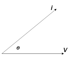
It is the cosine of angle between voltage and current
If Ɵis –ve or lagging (I lags V) then lagging P.F.
If Ɵ is +ve or leading (I leads V) then leading P.F.
If Ɵ is 0 or in phase (I and V in phase) then unity P.F.
Ac circuit containing pure resisting
Consider Circuit Consisting pure resistance connected across ac voltage source
V = Vm Sin ωt ①
According to ohm’s law i =  =
= 
But Im = 
 ②
②
Phases diagram
From ① and ② phase or represents RMD value.
Power P = V. i
Equation P = Vm sin ω t Im sin ω t
P = Vm Im Sin2 ω t
P =  -
- 

Constant fluctuating power if we integrate it becomes zero

Average power
Pavg = 
Pavg = 
Pavg = Vrms Irms
Power ware form [Resultant]
Ac circuit containing pure Inductors
Consider pure Inductor (L) is connected across alternating voltage. Source
V = Vm Sin ωt
When an alternating current flow through inductance it set ups alternating magnetic flux around the inductor.
This changing the flux links the coil and self-induced emf is produced
According to faradays Law of E M I
e = 
at all instant applied voltage V is equal and opposite to self-induced emf [ lenz’s law]
V = -e
 =
= 
But V = Vm Sin ωt
 dt
dt
Taking integrating on both sides
 dt
dt
 dt
dt
 (-cos
(-cos  )
)
but sin (– ) = sin (+
 )
)
 sin (
sin ( -
-  /2)
/2)
And Im= 
 /2)
/2)
 /2
/2
= -ve
= lagging
= I lag v by 900
Phasor:
Power P = Ѵ. I
= Vm sin wt Im sin (wt  /2)
/2)
= Vm Im Sin wt Sin (wt –  /s)
/s)
 ①
①
And
Sin (wt -  /s) = - cos wt ②
Sin (wt –  ) = - cos
 sin 2 wt from ① and ②
The average value of sin curve over a complete cycle is always zero
 Pavg = 0
Ac circuit containing pure capacitors:
Consider pure capacitor C is connected across alternating voltage source
Ѵ = Ѵm Sin wt
Current is passing through capacitor the instantaneous charge ɡ produced on the plate of capacitor
ɡ = C Ѵ
ɡ = c Vm sin wt
the current is rate of flow of charge

i= (cvm sin wt)
i = c Vm w cos wt
then rearranging the above eqth.
i =  cos wt

 = sin (wt +
  X/2)
X/2)
i =  sin (wt + X/2)
but 
 X/2)
X/2)

= leading
= I leads V by 900
Waveform :
Phase
Power P= Ѵ. i
= [Vm sinwt] [ Im sin (wt + X/2)]
= Vm Im Sin wt Sin (wt + X/2)]
 (cos wt)
 to charging power waveform [resultant].
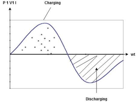
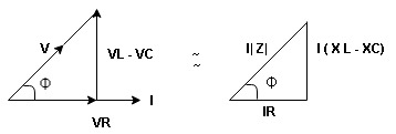
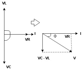
Series R-L Circuit
Consider a series R-L circuit connected across voltage source V= Vm sin wt
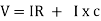
As some I is the current flowing through the resistor and inductor due do this current voltage drops arcos R and L R  VR = IR and L
  VL = I X L
 Total V = VR + VL
V = IR + I X L  V = I [R + X L]


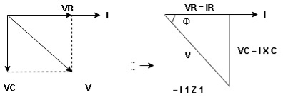
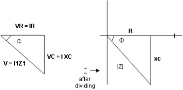
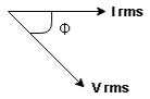
Take current as the reference phasor : 1) for resistor current is in phase with voltage 2) for Inductor voltage leads current or current lags voltage by 90 0.
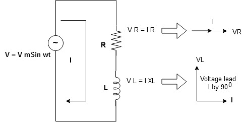
For voltage triangle
Ø is power factor angle between current and resultant voltage V and
V = 
V = 

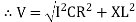
where Z = Impedance of circuit and its value is  =
= 
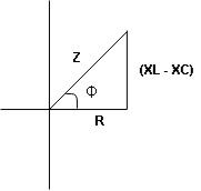
Impedance Triangle
Divide voltage triangle by I
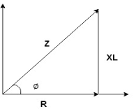
Rectangular form of Z = R+ixL
and polar from of Z =  L +
L + 
(+ j X L +  because it is in first quadrant )
Where  =
= 
 + Tan -1
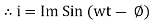
Current Equation :
From the voltage triangle we can sec. that voltage is leading current by  or current is legging resultant voltage by
Or i =  =
=  [ current angles - Ø )
Resultant Phasor Diagram from Voltage and current eqth.
Wave form

Power equation
P = V .I.
P = Vm Sin wt Im Sin wt – Ø
P = Vm Im (Sin wt) Sin (wt – Ø)
P =  (Cos Ø) - Cos (2wt – Ø)
Since 2 sin A Sin B = Cos (A-B) – Cos (A+B)
P =  Cos Ø -
  Cos (2wt – Ø)

①②
Average Power
pang =  Cos Ø
Cos Ø
Since ② term become zero because Integration of cosine come from 0 to 2ƛ
 pang = Vrms Irms cos Ø watts.
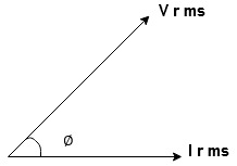
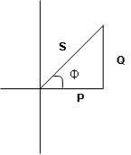
Power Triangle :
From 
VI = VRI + VLI B
Now cos Ø in  A =
A = 
 ①
①
Similarly Sin  =
= 


Apparent Power Average or true Reactive or useless power
Or real or active
-Unit (VI) Unit (Watts) C/W (VAR) denoted by (Ø)
Denoted by [S] denoted by [P]
Power  for R L ekt.
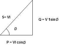
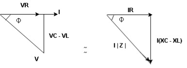
Series R-C circuit
V = Vm sin wt
VR

 I
I
R and C  voltage drops across.
R and C  R
R  VR = IR
And C  Vc = I
 c
c

 V =
V =  lZl
lZl
Voltage triangle : take current as the reference phasor 1) for resistor current is in phase with voltage 2) for capacitor current leads voltage or voltage lags behind current by 900
Where Ø is power factor angle between current and voltage (resultant) V
And from voltage
V = 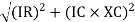
V = 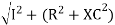
V = 
V =  lZl
lZl
Where Z = impedance of circuit and its value is lZl = 
Impendence triangle :
Divide voltage  by
by  as shown
Rectangular from of Z = R - jXc
Polar from of Z = lZl L - Ø
( - Ø and –jXc because it is in fourth quadrant ) where
lZl = 
and Ø = tan -1 
Current equation :
from voltage triangle we can see that voltage is lagging current by Ø or current is leading voltage by Ø
 i = IM Sin (wt + Ø) since Ø is +ve
Or i =  for RC
 LØ [ resultant current angle is + Ø]
Resultant phasor diagram from voltage and current equation
Resultant wave form :

Power Equation :
P = V. I
P = Vm sin wt. Im Sin (wt + Ø)
= Vm Im sin wt sin (wt + Ø)
2 Sin A Sin B = Cos (A-B) – Cos (A+B)
 -
- 
Average power
pang =  Cos Ø
Cos Ø
since 2 terms integration of cosine wave from 0 to 2ƛ become zero
 2 terms become zero
 pang = Vrms Irms Cos Ø
Power triangle RC Circuit:
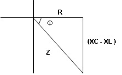
R-L-C series circuit
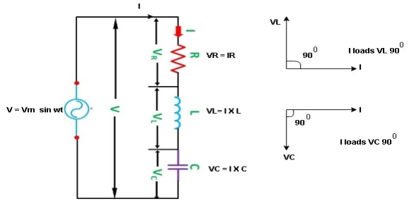
Consider ac voltage source V = Vm sin wt connected across combination of R L and C. when I flowing in the circuit voltage drops across each component as shown below.
VR = IR, VL = I  L, VC = I
  C
C
① XL> XC, ② XC> XL, ③ XL = XC
① XL > XC: Since we have assumed XL> XC
 Voltage drop across XL> than XC
 VL> VC A

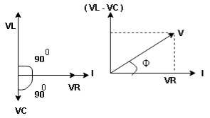
VL and VC are 180 0 out of phase .
Therefore cancel out each other
 Resultant voltage triangle
Now V = VR + VL + VC c phasor sum and VL and VC are directly in phase opposition and VL
 VC
VC their resultant is (VL - VC).
From voltage triangle
V = 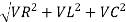
 V =
V = 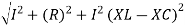
 V = I
V = I 

Impendence  : divide voltage
Rectangular form Z = R + j (XL – XC)
Polor form Z =  l + Ø B
Where  =
= 
And Ø = tan-1 
i =  from B
i =  L-Ø C
L-Ø C
as VL VC the circuit is mostly inductive and
  I lags behind V by angle Ø
 Since i =
  L-Ø
L-Ø
 i = Im Sin (wt – Ø) from c


 the voltage drops across XC
  than XL
 XC
XC  XL (A)
 voltage triangle considering condition (A)
 Resultant Voltage
Now V = VR + VL + VC  phases sum and VL and VC are directly in phase opposition and VC
 VL
VL  their resultant is (VC – VL)
From voltage 
V = 
V = 
 V =
V = 
 V =
V = 

 Impedance
  : Divide voltage
Polar form : Z =  L -
L -
Where 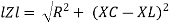
And Ø = tan-1 – 


as VC  the circuit is mostly capacitive and
  leads voltage by angle Ø
since i =  L + Ø
L + Ø
 Sin (wt – Ø) from C

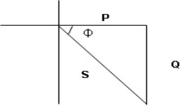
ɡȴ XL= XC then VL= VC and they are 1800 out of phase with each other  they will cancel out each other and their resultant will have zero value.
Hence resultant V = VR and it will be in phase with I as shown in below phasor diagram.
From above resultant phasor diagram
V =VR + IR
Or V = I  lZl
lZl
Because lZl + R
Thus Impedance Z is purely resistive for XL = XC and circuit current will be in phase with source voltage.

 Since VR= V Øis zero when XL = XC
  power is unity
ie pang = Vrms I rms cos Ø = 1 cos o = 1
maximum power will be transferred by condition. XL = XC
References:


