Unit – 2
Minimization of Boolean Functions
- Karnaugh map method or K-map method is the pictorial representation of the Boolean equations and Boolean manipulations are used to reduce the complexity in solving them. These can be considered as a special or extended version of the ‘Truth table’.
- Karnaugh map can be explained as “An array containing 2k cells in a grid like format, where k is the number of variables in the Boolean expression that is to be reduced or optimized”. As it is evaluated from the truth table method, each cell in the K-map will represent a single row of the truth table and a cell is represented by a square.
- The cells in the k-map are arranged in such a way that there are conjunctions, which differ in a single variable, are assigned in adjacent rows. The K-map method supports the elimination of potential race conditions and permits the rapid identification.
- By using Karnaugh map technique, we can reduce the Boolean expression containing any number of variables, such as 2-variable Boolean expression, 3-variable Boolean expression, 4-variable Boolean expression and even 7-variable Boolean expressions, which are complex to solve by using regular Boolean theorems and laws.
Minimization with Karnaugh Maps and advantages of K-map:
- K-maps are used to convert the truth table of a Boolean equation into minimized SOP form.
- Easy and simple basic rules for the simplification.
- The K-map method is faster and more efficient than other simplification techniques of Boolean algebra.
- All rows in the K-map are represented by using square shaped cells, in which each square in that will represent a minterms.
- It is easy to convert a truth table to k-map and k-map to Sum of Products form equation.
There are 2 forms in converting a Boolean equation into K-map:
- Un-optimized form: It involves in converting the number of 1’s into equal number of product terms (min terms) in an SOP equation.
- Optimized form: It involves in reducing the number of min terms in the SOP equation.
Grouping of K-map variables
- There are some rules to follow while we are grouping the variables in K-maps. They are
- The square that contains ‘1’ should be taken in simplifying, at least once.
- The square that contains ‘1’ can be considered as many times as the grouping is possible with it.
- Group shouldn’t include any zeros (0).
- A group should be the as large as possible.
- Groups can be horizontal or vertical. Grouping of variables in diagonal manner is not allowed.
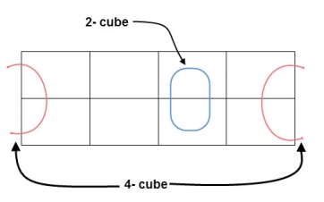
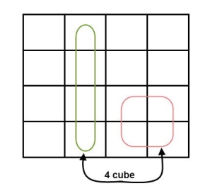
- If the square containing ‘1’ has no possibility to be placed in a group, then it should be added to the final expression.
- Groups can overlap.
- The number of squares in a group must be equal to powers of 2, such as 1, 2, 4, 8 etc.
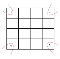
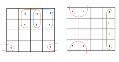
- Groups can wrap around. As the K-map is considered as spherical or folded, the squares at the corners (which are at the end of the column or row) should be considered as they adjacent squares.
- The grouping of K-map variables can be done in many ways, so they obtained simplified equation need not to be unique always.
- The Boolean equation must be in must be in canonical form, in order to draw a K-map.
2 variable K-maps
There are 4 cells (22) in the 2-variable k-map. It will look like (see below image)
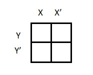
The possible min terms with 2 variables (A and B) are A.B, A.B’, A’. B and A’. B’. The conjunctions of the variables (A, B) and (A’, B) are represented in the cells of the top row and (A, B’) and (A’, B’) in cells of the bottom row. The following table shows the positions of all the possible outputs of 2-variable Boolean function on a K-map.

A general representation of a 2 variable K-map plot is shown below.
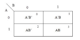
When we are simplifying a Boolean equation using Karnaugh map, we represent each cell of K-map containing the conjunction term with 1. After that, we group the adjacent cells with possible sizes as 2 or 4. In case of larger k-maps, we can group the variables in larger sizes like 8 or 16.
The groups of variables should be in rectangular shape that means the groups must be formed by combining adjacent cells either vertically or horizontally. Diagonal shaped or L-shaped groups are not allowed. The following example demonstrates a K-map simplification of a 2-variable Boolean equation.
Example
Simplify the given 2-variable Boolean equation by using K-map.
F = X Y’ + X’ Y + X’Y’
First, let’s construct the truth table for the given equation,
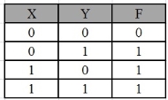
We put 1 at the output terms given in equation.
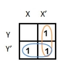
In this K-map, we can create 2 groups by following the rules for grouping, one is by combining (X’, Y) and (X’, Y’) terms and the other is by combining (X, Y’) and (X’, Y’) terms. Here the lower right cell is used in both groups.
After grouping the variables, the next step is determining the minimized expression.
By reducing each group, we obtain a conjunction of the minimized expression such as by taking out the common terms from two groups, i.e., X’ and Y’. So, the reduced equation will be X’ +Y’.
3 variable K-maps
For a 3-variable Boolean function, there is a possibility of 8 output min terms. The general representation of all the min terms using 3-variables is shown below.
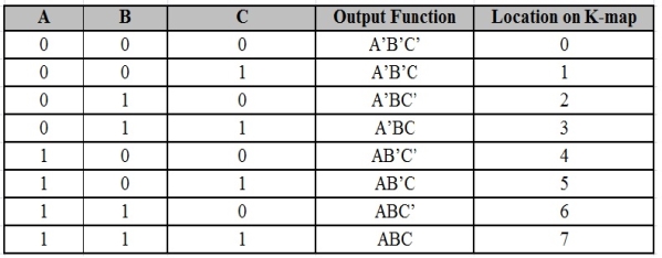
A typical plot of a 3-variable K-map is shown below. It can be observed that the positions of columns 10 and 11 are interchanged so that there is only change in one variable across adjacent cells. This modification will allow in minimizing the logic.
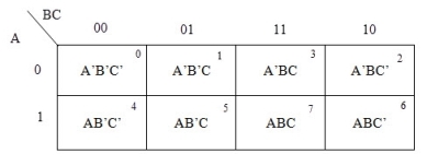
Up to 8 cells can be grouped in case of a 3-variable K-map with other possibilities being 1, 2 and 4.
Example
Simplify the given 3-variable Boolean equation by using k-map.
F = X’ Y Z + X’ Y’ Z + X Y Z’ + X’ Y’ Z’ + X Y Z + X Y’ Z’
First, let’s construct the truth table for the given equation,
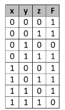
We put 1 at the output terms given in equation.
There are 8 cells (23) in the 3-variable k-map. It will look like (see below image).
The largest group size will be 8 but we can also form the groups of size 4 and size 2, by possibility. In the 3 variable Karnaugh map, we consider the left most column of the k-map as the adjacent column of rightmost column. So, the size 4 group is formed as shown below.
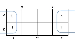
And in both the terms, we have ‘Y’ in common. So, the group of size 4 is reduced as the conjunction Y. To consume every cell which has 1 in it, we group the rest of cells to form size 2 group, as shown below.
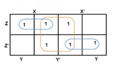
The 2-size group has no common variables, so they are written with their variables and its conjugates. So, the reduced equation will be X Z’ + Y’ + X’ Z. In this equation, no further minimization is possible.
4 variable K-maps
There are 16 possible min terms in case of a 4-variable Boolean function. The general representation of minterms using 4 variables is shown below.
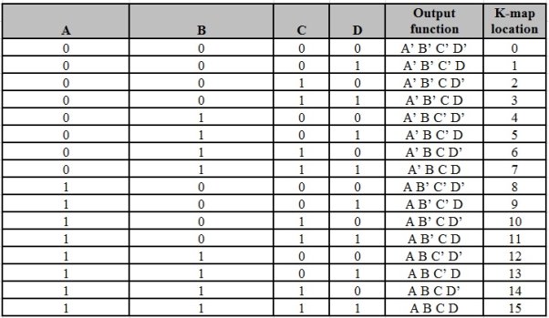
A typical 4-variable K-map plot is shown below. It can be observed that both the columns and rows of 10 and 11 are interchanged.
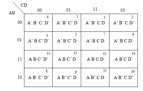
The possible numbers of cells that can be grouped together are 1, 2, 4, 8 and 16.
Example
Simplify the given 4-variable Boolean equation by using k-map. F (W, X, Y, Z) = (1, 5, 12, 13)
Sol: F (W, X, Y, Z) = (1, 5, 12, 13)
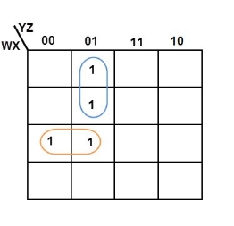
By preparing k-map, we can minimize the given Boolean equation as
F = W Y’ Z + W ‘Y’ Z
5 variable K-maps
A 5-variable Boolean function can have a maximum of 32 minterms. All the possible minterms are represented below
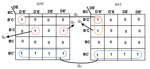
In 5-variable K-map, we have 32 cells as shown below. It is represented by F (A, B, C, D, and E). It is divided into two grids of 16 cells with one variable (A) being 0 in one grid and 1 in other grid.

Example
Simplify the given 5-variable Boolean equation by using k-map.
f (A, B, C, D, E) = ∑ m (0, 5, 6, 8, 9, 10, 11, 16, 20, 42, 25, 26, 27)
6 variable K-maps
A 6-variable Karnaugh map aids simplification of the logic for a 3-bit magnitude comparator. This is an overlay type of map. The binary address code across the top and down the left side of the map is not a full 3-bit Gray code.
Though the 2-bit address codes of the four sub maps is Gray code. Find redundant expressions by stacking the four sub maps atop one another (shown above). There could be cells common to all four maps, though not in the example below. It does have cells common to pairs of sub maps.

The A>B output above is ABC>XYZ on the map below.
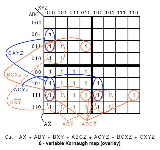
Where ever ABC is greater than XYZ, a 1 is plotted. In the first line ABC=000 cannot be greater than any of the values of XYZ. No 1s in this line. In the second line, ABC=001, only the first cell ABCXYZ= 001000 is ABC greater than XYZ. A single 1 is entered in the first cell of the second line. The fourth line, ABC=010, has a pair of 1s. The third line, ABC=011 has three 1s. Thus, the map is filled with 1s in any cells where ABC is greater than XXZ.
In grouping cells, form groups with adjacent sub maps if possible. All but one group of 16-cells involves cells from pairs of the sub maps. Look for the following groups:
- 1 group of 16-cells
- 2 groups of 8-cells
- 4 groups of 4-cells
The group of 16-cells, AX’ occupies all of the lower right sub map; though, we don’t circle it on the figure above.
One group of 8-cells is composed of a group of 4-cells in the upper sub map overlaying a similar group in the lower left map. The second group of 8-cells is composed of a similar group of 4-cells in the right sub map overlaying the same group of 4-cells in the lower left map.
The four groups of 4-cells are shown on the Karnaugh map above with the associated product terms. Along with the product terms for the two groups of 8-cells and the group of 16-cells, the final Sum-Of-Products reduction is shown, all seven terms.
Counting the 1s in the map, there is a total of 16+6+6=28 ones. Before the K-map logic reduction there would have been 28 product terms in our SOP output, each with 6-inputs. The Karnaugh map yielded seven product terms of four or less inputs. This is really what Karnaugh maps are all about!
The wiring diagram is not shown. However, here is the parts list for the 3-bit magnitude comparator for ABC>XYZ using 4 TTL logic family parts:
- 7410 triple 3-input NAND gate AX’, ABY’, BX’Y’
- 7420 dual 4-input NAND gate ABCZ’, ACY’Z’, BCX’Z’, CX’Y’Z’
- 7430 8-input NAND gate for output of 7-P-terms
- Karnaugh introduced a method for simplification of Boolean functions in a very easy way.
- This method is known as Karnaugh map method or K-map method.
- It is a graphical method, which comprises of 2n cells for ‘n’ variables.
- Here, the adjacent cells vary only in single bit position.
Prime implicant is a product (or sum) term, which cannot be further reduced by combining with any other product (or sum) terms in the given Boolean function.
- K-map method is a convenient method for the minimization of Boolean functions up to 5 variables. But it is very difficult to simplify more than 5 variables by using this method.
- Quine-McCluskey is a tabular method based on the concept of prime implicants.
- Prime implicant is a product (or sum) term, which cannot be further reduced by combining with any other product (or sum) terms in the given Boolean function.
- This tabular method gets the prime implicants by repeatedly using the following Boolean identity.
Xy + xy’ = x (y + y’) = x.1 = x
The procedure of Quine-McCluskey Tabular Method
Steps for simplifying Boolean functions using the Quine-McCluskey method:
Step 1 − Arranging the given min terms in ascending order and making groups based on the number of one’s presence in the binary representations.
So, there are at most ‘n+1’ groups if there are ‘n’ Boolean variables or ‘n’ bits in the binary equivalent of min terms.
Step 2 − Comparing the min terms present in successive groups. If there is a change in only a one-bit position, then taking the pair of two min terms. Placing the symbol ‘_’ in the differed bit position and keeping the remaining bits as it is.
Step 3 − Repeating step2 with newly formed terms until we get all required prime implicants.
Step 4 − Formulating the prime implicant table which consists of a set of rows and columns. It can be placed row-wise and min terms can be placed column-wise. Put ‘1’ in the cells corresponding to the min terms that are covered in each prime implicant.
Step 5 – Now find the essential prime implicants by observing each column. If the minterm is covered by one prime implicant, then it is called as essential prime implicant. They will be a part of the simplified Boolean function.
Step 6 – The prime implicant table is reduced by removing the row and columns of each essential prime implicant corresponding to the min terms. This process is stopped when all min terms of given Boolean function are over.
Example
Simplify, f (W, X, Y, Z) =∑m (2,6,8,9,10,11,14,15) and f (W, X, Y, Z) =∑m (2,6,8,9,10,11,14,15)
Using Quine-McCluskey tabular method.
Solution:
Group Name | Min terms | W | X | Y | Z |
GA1 | 2 | 0 | 0 | 1 | 0 |
8 | 1 | 0 | 0 | 0 | |
GA2 | 6 | 0 | 1 | 1 | 0 |
9 | 1 | 0 | 0 | 1 | |
10 | 1 | 0 | 1 | 0 | |
GA3 | 11 | 1 | 0 | 1 | 1 |
14 | 1 | 1 | 1 | 0 | |
GA4 | 15 | 1 | 1 | 1 | 1 |
Group Name | Min terms | W | X | Y | Z |
GB1 | 2,6 | 0 | - | 1 | 0 |
2,10 | - | 0 | 1 | 0 | |
8,9 | 1 | 0 | 0 | - | |
8,10 | 1 | 0 | - | 0 | |
GB2 | 6,14 | - | 1 | 1 | 0 |
9,11 | 1 | 0 | - | 1 | |
10,11 | 1 | 0 | 1 | - | |
10,14 | 1 | - | 1 | 0 | |
GB3 | 11,15 | 1 | - | 1 | 1 |
14,15 | 1 | 1 | 1 | - | |
|
|
|
|
|
|
Group Name | Min terms | W | X | Y | Z |
GB1 | 2,6,10,14 | - | - | 1 | 0 |
2,10,6,14 | - | - | 1 | 0 | |
8,9,10,11 | 1 | 0 | - | - | |
8,10,9,11 | 1 | 0 | - | - | |
GB2 | 10,11,14,15 | 1 | - | 1 | - |
10,14,11,15 | 1 | - | 1 | - | |
|
|
|
|
|
|
Group Name | Min terms | W | X | Y | Z |
GC1 | 2,6,10,14 | - | - | 1 | 0 |
| 8,9,10,11 | 1 | 0 | - | - |
GC2 | 10,11,14,15 | 1 | - | 1 | - |
Therefore, the prime implicants are YZ’, WX’ & WY.
The prime implicant table is shown below.
Min terms / Prime Implicants | 2 | 6 | 8 | 9 | 10 | 11 | 14 | 15 |
YZ’ | 1 | 1 |
|
| 1 |
| 1 |
|
WX’ |
|
| 1 | 1 | 1 | 1 |
|
|
WY |
|
|
|
| 1 | 1 | 1 | 1 |
The reduced prime implicant table is shown below.
Min terms / Prime Implicants | 8 | 9 | 11 | 15 |
WX’ | 1 | 1 | 1 |
|
WY |
|
| 1 | 1 |
Min terms / Prime Implicants | 15 |
WY | 1 |
Hence, f (W, X, Y, Z) = YZ’ + WX’ + WY.
Simplify (ref: internet)
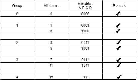
Y (A, B, C, D) =∑ m (0,1,3,7,8,9,11,15)
Groups are made with respect to the no. Of one’s present.
Now, comparing with the above table wherever we have a different bit present we put a ’-‘ there.
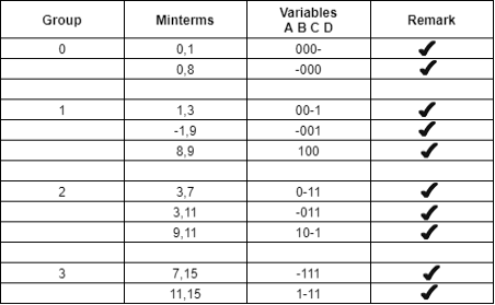
The same thing is done by comparing it from the above table.
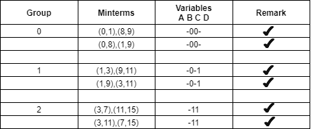
The table for prime implicants is:
PI terms | Group of minterms | Minterms 0 1 3 7 8 9 11 15 |
B’C’ | 0,1,8,9 |
|
B’D | 1,3,9,11 | X X X X |
CD | 3,7,11,15 |
|
Rounding the min terms which has X in the column and hence the final answer is B’C’ + CD.
AND gate
It is a digital circuit that consists of two or more inputs and a single output which is the logical AND of all those inputs. It is represented with the symbol ‘.’.
The following is the truth table of 2-input AND gate.
A | B | Y = A.B |
0 | 0 | 0 |
0 | 1 | 0 |
1 | 0 | 0 |
1 | 1 | 1 |
Here A, B are the inputs and Y is the output of two input AND gate.
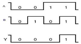
If both inputs are ‘1’, then only the output, Y is ‘1’. For remaining combinations of inputs, the output, Y is ‘0’.
The figure below shows the symbol of an AND gate, which is having two inputs A, B and one output, Y.

Fig.: AND gate
Timing Diagram:
OR gate
It is a digital circuit which has two or more inputs and a single output which is the logical OR of all those inputs. It is represented with the symbol ‘+’.
The truth table of 2-input OR gate is:
A | B | Y = A + B |
0 | 0 | 0 |
0 | 1 | 1 |
1 | 0 | 1 |
1 | 1 | 1 |
Here A, B are the inputs and Y is the output of two input OR gate.
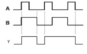
When both inputs are ‘0’, then only the output, Y is ‘0’. For remaining combinations of inputs, the output, Y is ‘1’.
The figure below shows the symbol of an OR gate, which is having two inputs A, B and one output, Y.

Fig.: OR gate
Timing Diagram:
NOT gate
It is a digital circuit that has one input and one output. Here the output is the logical inversion of input. Hence, it is also called as an inverter.
The truth table of NOT gate is:
A | Y = A’ |
0 | 1 |
1 | 0 |
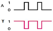
Here A and Y are the corresponding input and output of NOT gate. When A is ‘0’, then, Y is ‘1’. Similarly, when, A is ‘1’, then, Y is ‘0’.
The figure below shows the symbol of NOT gate, which has one input, A and one output, Y.

Fig.: NOT gate (ref. 1)
Timing Diagram:
Special Gates
Ex-OR gate
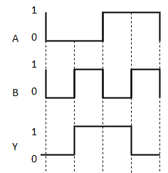
It stands for Exclusive-OR gate. Its function varies when the inputs have even number of ones.
The truth table of 2-input Ex-OR gate is:
A | B | Y = A⊕B |
0 | 0 | 0 |
0 | 1 | 1 |
1 | 0 | 1 |
1 | 1 | 0 |
Here A, B are the inputs and Y is the output of two input Ex-OR gate. The output (Y) is zero instead of one when both the inputs are one.
Therefore, the output of Ex-OR gate is ‘1’, when only one of the two inputs is ‘1’. And it is zero, when both inputs are same.
The symbol of Ex-OR gate is as follows:

Fig.: XOR gate (ref. 1)
It is similar to that of OR gate with an exception for few combination(s) of inputs. Hence, the output is also known as an odd function.
Timing Diagram:
Ex-NOR gate
It stands for Exclusive-NOR gate. Its function is same as that of NOR gate except when the inputs having even number of ones.
The truth table of 2-input Ex-NOR gate is:
A | B | Y = A⊙B |
0 | 0 | 1 |
0 | 1 | 0 |
1 | 0 | 0 |
1 | 1 | 1 |
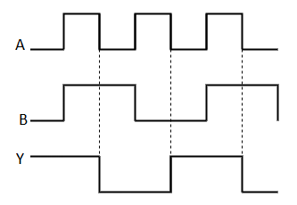
Here A, B are the inputs and Y is the output. It is same as Ex-NOR gate with the only modification in the fourth row. The output is 1 instead of 0, when both the inputs are one.
Hence the output of Ex-NOR gate is ‘1’, when both inputs are same and 0, when both the inputs are different.
The symbol of Ex-NOR gate is:

Fig.: XNOR gate
It is similar to NOR gate except for few combination(s) of inputs. Here the output is ‘1’, when even number of 1 is present at the inputs. Hence is also called as an even function.
Timing Diagram:
- NAND & NOR gates are known as universal gates.
- We can implement any Boolean function by using NAND gates and NOR gates alone.
NAND gate
It is a digital circuit which has two or more inputs and single output and it is the inversion of logical AND gate.
The truth table of 2-input NAND gate is:
A | B | Y = (A.B)’ |
0 | 0 | 1 |
0 | 1 | 1 |
1 | 0 | 1 |
1 | 1 | 0 |
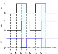
Here A, B are the inputs and Y is the output of two input NAND gate. When both inputs are ‘1’, then the output, Y is ‘0’. If at least one of the input is zero, then the output, Y is ‘1’. This is just the inverse of AND operation.
The image shows the symbol of NAND gate:

Fig.: NAND gate
NAND gate works same as AND gate followed by an inverter.
Timing Diagram:
NOR gate
It is a digital circuit that has two or more inputs and a single output which is the inversion of logical OR of all inputs.
The truth table of 2-input NOR gate is:
A | B | Y = (A+B)’ |
0 | 0 | 1 |
0 | 1 | 0 |
1 | 0 | 0 |
1 | 1 | 0 |
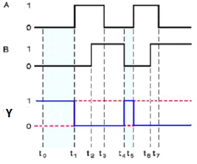
Here A and B are the two inputs and Y is the output. If both inputs are ‘0’, then the output is ‘1’. If any one of the input is ‘1’, then the output is ‘0’. This is exactly opposite to two input OR gate operation.
The symbol of NOR gate is:

Fig.: NOR gate
NOR gate works exactly same as that of OR gate followed by an inverter.
Timing Diagram:
References:
1. Anand Kumar, “Fundamentals of Digital Circuits”, Prentice Hall of India, 1st Edition.
2. J. F. Wakerly, “Digital Design- Principles and Practices,”, Pearson, 3rd Edition.
3. M. M. Mano, “Digital Design,” Prentice Hall India.


