Unit - 3
Coding and Software Testing Techniques
● Coding is done when the design phase is over and the design documents are successfully reviewed.
● Coding is the process of transforming the design of & a system to computer language format.
● Coding is done by the coder or programmers who are independent people then the designers.
Coding Standards & Guidelines
● General and good coding standards refers to how the developers write codes that suit the organization.
The following are some representative coding standards: -
Coding guidelines:
General coding guidelines provide the programmer with a set of best methods which can make the programs more comfortable to read & maintain. The following are some guidelines: -
Code Review
Code review is a systematic examination of computer source code. It is intended to find and fix mistakes overlooked in the initial development phase, thus improving overall quality of the software as well as the developer’s skill.
Generally, the following two types of reviews are carried out on the code. They are:
Walkthroughs
● A structured walkthrough is an in-depth, technical review of some aspects of a software system. Walkthroughs can be anytime, during any phase of a software project.
● A walkthrough team consists of 4 to 6 people. The person whose material is being reviewed is responsible for providing copies of the review materials to the members of the walkthrough group in advance of the walkthrough session and the team members are responsible for understanding the reviewing material before the session.
● During the walkthrough the reviewed “walks through” the material while the reviewers look for errors, request clarification and explore problem areas in the material under review.
● High-level managers should not attend walkthrough sessions as the aim of walkthroughs is error detection not corrective action. It’s important to note that the material is reviewed, not the person whose material is being reviewed.
Inspections
● Design inspections are conducted by teams of trained inspectors who have a checklist of items to be examined.
● Special forms are used to record problems encountered.
● A typical inspection team consists of a Moderator or Secretary, a Designer, an Implementer and a Tester. The Designer, Implementer and Tester may or may not be the people responsible for the actual design, implementation and testing of the product being inspected.
● The team members are trained for their specific roles and typically conduct a dual 2-hrs sessions per day.
Documentation
Code documentation is a type of manual or guide that aids in the understanding and proper application of software code. The designer benefits from coding standards and naming conventions stated in a frequently spoken language in code documentation.
Additionally, they serve as a guide for the software maintenance team (who is responsible for sustaining software by upgrading and upgrading it after it has been provided to the end user) during the software maintenance process. Code documentation aids reusability in this way.
Source code is included in code documentation, which is helpful to software developers while writing software code. Various coding tools that are used to auto-generate code documents can be used to create code documents. In other words, these documents extract comments from source code and turn them into a text or HTML file that serves as a reference manual.
The auto-generated code facilitates the extraction of source code from comments by software developers. Application programming interfaces, data structures, and algorithms are all included in this documentation. Internal documentation and external documentation are the two types of code documentation.
Internal documentation should explain how each code section in the software connects to user needs. Internal documentation often includes the following information.
● Each variable and data structure utilized in the code has a name, type, and purpose.
● Algorithms, logic, and error-handling approaches are briefly described.
● Information on the program's required input and expected outcome.
● Instructions on how to test the software are provided.
● Information on the program's upgrades and enhancements.
External documentation is a type of documentation that focuses on a broad overview of software code rather than specific details. External documentation typically contains structure charts that provide a program outline and describe the program's architecture.
External documentation is beneficial to software developers since it contains information such as a problem description and the program built to solve it.
Key takeaway:
Unit testing focuses verification effort on the smallest unit of software design—the software component or module. Using the component- level design description as a guide, important control paths are tested to uncover errors within the boundary of the module. The relative complexity of tests and uncovered errors is limited by the constrained scope established for unit testing. The unit test is white-box oriented, and the step can be conducted in parallel for multiple components.
Unit Test Considerations
The tests that occur as part of unit tests are illustrated schematically in Figure below. The module interface is tested to ensure that information properly flows into and out of the program unit under test. The local data structure is examined to ensure that data stored temporarily maintains its integrity during all steps in an algorithm's execution. Boundary conditions are tested to ensure that the module operates properly at boundaries established to limit or restrict processing. All independent paths (basis paths) through the control structure are exercised to ensure that all statements in a module have been executed at least once. And finally, all error handling paths are tested.
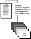
Fig 1: Unit Test
Tests of data flow across a module interface are required before any other test is initiated. If data does not enter and exit properly, all other tests are moot. In addition, local data structures should be exercised and the local impact on global data should be ascertained (if possible) during unit testing.
Selective testing of execution paths is an essential task during the unit test. Test cases should be designed to uncover errors due to erroneous computations, incorrect comparisons, or improper control flow. Basis path and loop testing are effective techniques for uncovering a broad array of path errors.
Among the more common errors in computation are
● Misunderstood or incorrect arithmetic precedence,
● Mixed mode operations,
● Incorrect initialization,
● Precision inaccuracy,
● Incorrect symbolic representation of an expression.
Comparison and control flow are closely coupled to one another (i.e., change of flow frequently occurs after a comparison). Test cases should uncover errors such as
Among the potential errors that should be tested when error handling is evaluated are
● Error description is unintelligible.
● Error noted does not correspond to error encountered.
● Error condition causes system intervention prior to error handling.
● Exception-condition processing is incorrect.
● Error description does not provide enough information to assist in the location of the cause of the error.
Boundary testing is the last (and probably most important) task of the unit test step. Software often fails at its boundaries. That is, errors often occur when the nth element of an n-dimensional array is processed, when the ith repetition of a loop with i passes is invoked, when the maximum or minimum allowable value is encountered. Test cases that exercise data structure, control flow, and data values just below, at, and just above maxima and minima are very likely to uncover errors.
Unit Test Procedures
Unit testing is normally considered as an adjunct to the coding step. After source level code has been developed, reviewed, and verified for correspondence to component level design, unit test case design begins. A review of design information provides guidance for establishing test cases that are likely to uncover errors in each of the categories discussed earlier. Each test case should be coupled with a set of expected results.
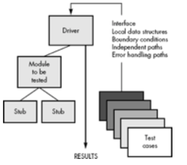
Fig 2: Unit Test Environment
Because a component is not a stand-alone program, driver and/or stub software must be developed for each unit test. The unit test environment is illustrated in Figure above. In most applications a driver is nothing more than a "main program" that accepts test case data, passes such data to the component (to be tested), and prints relevant results. Stubs serve to replace modules that are subordinate (called by) the component to be tested.
A stub or "dummy subprogram" uses the subordinate module's interface, may do minimal data manipulation, prints verification of entry, and returns control to the module undergoing testing. Drivers and stubs represent overhead. That is, both are software that must be written (formal design is not commonly applied) but that is not delivered with the final software product. If drivers and stubs are kept simple, actual overhead is relatively low. Unfortunately, many components cannot be adequately unit tested with "simple" overhead software. In such cases, complete testing can be postponed until the integration test step (where drivers or stubs are also used).
Unit testing is simplified when a component with high cohesion is designed. When only one function is addressed by a component, the number of test cases is reduced and errors can be more easily predicted and uncovered.
Advantage of Unit Testing
● Can be applied directly to object code and does not require processing source code.
● Performance profilers commonly implement this measure.
Disadvantages of Unit Testing
Key takeaway:
It is also known as “behavioural testing” which focuses on the functional requirements of the software, and is performed at later stages of the testing process unlike white box which takes place at an early stage. Black-box testing aims at functional requirements for a program to derive sets of input conditions which should be tested. Black box is not an alternative to white-box, rather, it is a complementary approach to find out a different class of errors other than white-box testing.
Black-box testing is emphasizing on different set of errors which falls under following categories:
Advantages:
● More effective on larger units of code than glass box testing.
● Testers need no knowledge of implementation, including specific programming languages.
● Testers and programmers are independent of each other.
● Tests are done from a user's point of view.
● Will help to expose any ambiguities or inconsistencies in the specifications.
● Test cases can be designed as soon as the specifications are complete.
Disadvantages:
● Only a small number of possible inputs can actually be tested, to test every possible input stream would take nearly forever.
● Without clear and concise specifications, test cases are hard to design.
● There may be unnecessary repetition of test inputs if the tester is not informed of test cases the programmer has already tried.
● May leave many program paths untested.
● Cannot be directed toward specific segments of code which may be very complex (and therefore more error prone).
● Most testing related research has been directed toward glass box testing.
Key takeaway:
● In this testing technique the internal logic of software components is tested.
● It is a test case design method that uses the control structure of the procedural design test cases.
● It is done in the early stages of software development.
● Using this testing technique software engineer can derive test cases that:
● All independent paths within a module have been exercised at least once.
● Exercise true and false both the paths of logical checking.
● Execute all the loops within their boundaries.
● Exercise internal data structures to ensure their validity.
Advantages:
● As the knowledge of internal coding structure is prerequisite, it becomes very easy to find out which type of input/data can help in testing the application effectively.
● The other advantage of white box testing is that it helps in optimizing the code.
● It helps in removing the extra lines of code, which can bring in hidden defects.
● We can test the structural logic of the software.
● Every statement is tested thoroughly.
● Forces test developers to reason carefully about implementation.
● Approximate the partitioning done by execution equivalence.
● Reveals errors in "hidden" code.
Disadvantages:
● It does not ensure that the user requirements are fulfilled.
● As knowledge of code and internal structure is a prerequisite, a skilled tester is needed to carry out this type of testing, which increases the cost.
● It is nearly impossible to look into every bit of code to find out hidden errors, which may create problems, resulting in failure of the application.
● The tests may not be applicable in a real-world situation.
● Cases omitted in the code could be missed out.
Key takeaway:
Cyclomatic complexity is a measure of source code complexity that is linked to a number of coding faults. It's calculated by creating a code Control Flow Graph that counts the number of linearly independent paths through a program module.
The number of linearly independent pathways in a code segment is measured in terms of cyclomatic complexity. It's a software statistic that shows how complicated a program is. It is calculated using the program's Control Flow Graph. The graph's nodes represent the smallest collection of commands in a program, and a directed edge connects the two nodes, indicating that the second instruction may immediately follow the first.
The directed graph inside control flow is the edge connecting two basic blocks of the program mathematically, as control may transfer from first to second.
As a result, cyclomatic complexity M is defined as,
Cyclomatic complexity = E - N + 2*P
where,
E = number of edges in the flow graph.
N = number of nodes in the flow graph.
P = number of nodes that have exit points
Example:
A = 10
IF B > C THEN
A = B
ELSE
A = C
ENDIF
Print A
Print B
Print C
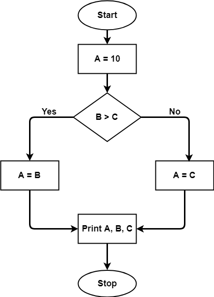
Fig 3: control flow graph
The control flow graph will be used to calculate the cyclomatic complexity for the above code. Because there are seven shapes (nodes) and seven lines (edges) in the graph, the cyclomatic complexity is 7-7+2 = 2.
Advantages
● It can be used as a quality metric, giving relative complexity of various designs.
● It is able to compute faster than Halstead's metrics.
● It is used to measure the minimum effort and best areas of concentration for testing.
● It is able to guide the testing process.
● It is easy to apply.
Disadvantages
● It is the measure of the program's control complexity and not the data's data complexity.
● In this, nested conditional structures are harder to understand than non-nested structures.
Key takeaway
The process of code coverage analysis entails:
● Identifying portions of a software that aren't being tested by a set of test cases,
● Adding more test cases to boost coverage, as well as.
● Developing a quantifiable measure of code coverage, which serves as an indirect quality indicator.
The following is an optional feature of code coverage analysis:
● Identifying test cases that are redundant and do not add to coverage.
This is done with the help of a code coverage analyzer.
Code coverage is a software testing statistic, also known as Code Coverage Testing, that aids in evaluating how much source code is checked, which aids in establishing the quality of the test suite and examining how thoroughly a software is validated. In reality, code coverage refers to the extent to which the software code's source code has been tested. This type of white box testing is referred to as Code Coverage.
As we all know, at the end of the development process, each client desires a high-quality software product, and the developer team is also accountable for delivering a high-quality software product to the customer. The product's performance, functionality, behavior, accuracy, reliability, effectiveness, security, and maintainability are all examples of quality. The Code Coverage statistic is used to determine the performance and quality of software.
The formula for calculating code coverage is as follows:
Code Coverage = (Number of lines of code executed)/ (Total Number of lines of code in a system component) * 100
Key takeaway
Code coverage is a software testing statistic, also known as Code Coverage Testing, that aids in evaluating how much source code is checked, which aids in establishing the quality of the test suite and examining how thoroughly a software is validated.
Mutation testing is a white box software testing method in which we purposefully introduce defects into a program (under test) to see if the existing test case can detect the issue. The mutant of the program is developed in this testing by adding various changes to the original program.
The fundamental goal of mutation testing is to determine whether each mutant produced an output that is distinct from the original program's result. We'll make little changes to the mutant program because changing it on a large scale will have an impact on the entire strategy.
When we find a large number of mistakes, it means either the software is correct or the test case is ineffective at detecting the problem.
The purpose of mutation testing is to evaluate the quality of the case that should be able to fail the mutant code; therefore, this method is also known as Fault-based testing because it is used to produce an error in the program; thus, mutation testing is performed to check the efficiency of the test cases.
Types of Mutation Testing
Testing for mutations can be broken down into three categories:
As an example, consider the following arithmetic operator changes:
● plus (+) → minus (-)
● asterisk (*) → double asterisk (**)
● plus (+) →incremental operator(i++)
As an example, consider the following logical operator changes:
● Exchange P > → P<, OR P>=
Let's look at an example to help us understand:
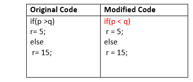
2. Value mutation: The values will change to detect the program's problems, and we will normally update the following:
For example:
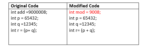
3. Statement mutation: Statement mutations imply that we can make changes to statements by removing or replacing lines, as shown in the following example:
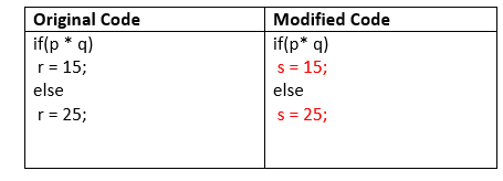
In the above case, we have replaced the statement r=15 by s=15, and r=25 by s=25.
Advantages
● It is a right approach for error detection to the application programmer
● The mutation testing is an excellent method to achieve the extensive coverage of the source program.
● Mutation testing helps us to give the most established and dependable structure for the clients.
● This technique can identify all the errors in the program and also helps us to discover the doubts in the code.
Disadvantages
● This testing is a bit of time taking and costlier process because we have many mutant programs that need to be created.
● The mutation testing is not appropriate for Black-box testing as it includes the modification in the source code.
● Every mutation will have the same number of test cases as compare to the actual program. Therefore, the significant number of the mutant program may need to be tested beside the real test suite.
● As it is a tedious process, so we can say that this testing requires the automation tools to test the application.
Key takeaway
Debugging is the method of repairing a bug in the programme in the sense of software engineering. In other words, it applies to error detection, examination and elimination. This operation starts after the programme fails to function properly and ends by fixing the issue and checking the software successfully. As errors need to be fixed at all levels of debugging, it is considered to be an extremely complex and repetitive process.
Debugging process
Steps that are involved in debugging include:
● Identification of issues and preparation of reports.
● Assigning the software engineer's report to the defect to verify that it is true.
● Defect Detection using modelling, documentation, candidate defect finding and checking, etc.
● Defect Resolution by having the device modifications required.
● Corrections validation.
Debugging strategies -
Key takeaway:
Integration testing is a systematic technique for constructing the program structure while at the same time conducting tests to uncover errors associated with interfacing. The objective is to take unit tested components and build a program structure that has been dictated by design.
There is often a tendency to attempt non incremental integration; that is, to construct the program using a "big bang" approach. All components are combined in advance. The entire program is tested as a whole. And chaos usually results! A set of errors is encountered.
Correction is difficult because isolation of causes is complicated by the vast expanse of the entire program. Once these errors are corrected, new ones appear and the process continues in a seemingly endless loop.
Incremental integration is the antithesis of the big bang approach. The program is constructed and tested in small increments, where errors are easier to isolate and correct; interfaces are more likely to be tested completely; and a systematic test approach may be applied.
Top-down Integration
Top-down integration testing is an incremental approach to construction of program structure. Modules are integrated by moving downward through the control hierarchy, beginning with the main control module (main program). Module’s subordinate (and ultimately subordinate) to the main control module is incorporated into the structure in either a depth-first or breadth-first manner.
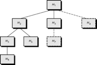
Fig 4: Top-down integration
Referring to Figure above, depth-first integration would integrate all components on a major control path of the structure. Selection of a major path is somewhat arbitrary and depends on application-specific characteristics. For example, selecting the left-hand path, components M1, M2, M5 would be integrated first. Next, M8 or (if necessary for proper functioning of M2) M6 would be integrated.
Then, the central and right-hand control paths are built. Breadth-first integration incorporates all components directly subordinate at each level, moving across the structure horizontally. From the figure, components M2, M3, and M4 (a replacement for stub S4) would be integrated first. The next control level, M5, M6, and so on, follows.
The integration process is performed in a series of five steps:
● The main control module is used as a test driver and stubs are substituted for all components directly subordinate to the main control module.
● Depending on the integration approach selected (i.e., depth or breadth first), subordinate stubs are replaced one at a time with actual components.
● Tests are conducted as each component is integrated.
● On completion of each set of tests, another stub is replaced with the real component.
● Regression testing may be conducted to ensure that new errors have not been introduced. The process continues from step 2 until the entire program structure is built.
The top-down integration strategy verifies major control or decision points early in the test process. In a well-factored program structure, decision making occurs at upper levels in the hierarchy and is therefore encountered first. If major control problems do exist, early recognition is essential. If depth-first integration is selected, a complete function of the software may be implemented and demonstrated.
For example, consider a classic transaction structure in which a complex series of interactive inputs is requested, acquired, and validated via an incoming path. The incoming path may be integrated in a top-down manner. All input processing (for subsequent transaction dispatching) may be demonstrated before other elements of the structure have been integrated. Early demonstration of functional capability is a confidence builder for both the developer and the customer.
Top-down strategy sounds relatively uncomplicated, but in practice, logistical problems can arise. The most common of these problems occurs when processing at low levels in the hierarchy is required to adequately test upper levels. Stubs replace low-level modules at the beginning of top-down testing; therefore, no significant data can flow upward in the program structure. The tester is left with three choices:
The first approach (delay tests until stubs are replaced by actual modules) causes us to loose some control over correspondence between specific tests and incorporation of specific modules. This can lead to difficulty in determining the cause of errors and tends to violate the highly constrained nature of the top-down approach. The second approach is workable but can lead to significant overhead, as stubs become more and more complex.
Bottom-up Integration
Bottom-up integration testing, as its name implies, begins construction and testing with atomic modules (i.e., components at the lowest levels in the program structure). Because components are integrated from the bottom up, processing required for components subordinate to a given level is always available and the need for stubs is eliminated.
A bottom-up integration strategy may be implemented with the following steps:
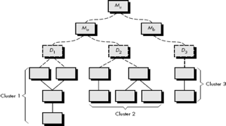
Fig 5: Bottom-up integration
Integration follows the pattern illustrated in Figure above. Components are combined to form clusters 1, 2, and 3. Each of the clusters is tested using a driver (shown as a dashed block). Components in clusters 1 and 2 are subordinate to Ma. Drivers D1 and D2 are removed and the clusters are interfaced directly to Ma. Similarly, driver D3 for cluster 3 is removed prior to integration with module Mb. Both Ma and Mb will ultimately be integrated with component Mc, and so forth.
As integration moves upward, the need for separate test drivers lessens. In fact, if the top two levels of program structure are integrated top down, the number of drivers can be reduced substantially and integration of clusters is greatly simplified.
Key takeaway:
Software is the only one element of a larger computer-based system. Ultimately, software is incorporated with other system elements (e.g., hardware, people, information), and a series of system integration and validation tests are conducted. These tests fall outside the scope of the software process and are not conducted solely by software engineers. However, steps taken during software design and testing can greatly improve the probability of successful software integration in the larger system.
A classic system testing problem is "finger-pointing." This occurs when an error is uncovered, and each system element developer blames the other for the problem. Rather than indulging in such nonsense, the software engineer should anticipate potential interfacing problems and
● Design error-handling paths that test all information coming from other elements of the system,
● Conduct a series of tests that simulate bad data or other potential errors at the software interface,
● Record the results of tests to use as "evidence" if finger-pointing does occur, and
● Participate in planning and design of system tests to ensure that software is adequately tested.
System testing is actually a series of different tests whose primary purpose is to fully exercise the computer-based system. Although each test has a different purpose, all work to verify that system elements have been properly integrated and perform allocated functions.
Key takeaway:
Regression testing is a type of black box testing. It is used to verify that a software code modification does not affect the product's existing functionality. Regression testing ensures that a product's new functionality, issue patches, or other changes to an existing feature work properly.
Software regression testing is a sort of testing. Test cases are re-run to ensure that the application's previous functionality is still operational and that the new changes haven't introduced any defects.
When there is a significant change in the original functionality, regression testing can be performed on a new build. It ensures that the code continues to function even as modifications are made.
Regression testing refers to re-testing the elements of the application that haven't changed.
The Verification Method is another name for regression tests. Many test cases are automated. Test cases must be run multiple times, and manually repeating the same test case over and over is time-consuming and tiresome.
Regression Testing Steps:
Regression tests are the ideal cases of automation which results in better Return on Investment (ROI).
● Select the Tests for Regression.
● Choose the apt tool and automate the Regression Tests
● Verify applications with Checkpoints
● Manage Regression Tests/update when required
● Schedule the tests
● Integrate with the builds
● Analyze the results
Key takeaway
Software reliability was created to predict the number of defects or faults in the software. Software reliability is the probability that the software will execute properly without any failure for a given period of time. Reliability is concerned with how well the software functions to meet the requirements of the customer. It represents a user-oriented view of the software quality.
The two terms related to software reliability are-
Software reliability is hard to achieve, because the complexity of software tends to be high. While the complexity of software is inversely related to software reliability it is directly related to other important factors like software quality, especially functionality, capability.
Hardware versus Software Reliability
In any software industry, system quality plays an important role. It comprises hardware quality and software quality. We know that hardware quality is constantly high. So, if the system quality changes, it is because of the variation in software quality only.
Hardware components basically fail due to wear and tear, whereas software components fail due to bugs. To fix the hardware fault, we have to either repair or replace the failed parts. On the other hand, to fix software faults one has to track down until the error is encountered or the design is changed to fix the bug. Doing this the hardware reliability would remain the same, but software reliability would either increase or decrease.
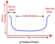
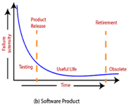
Fig 6: Change in failure rate of a product
Reliability Metrics
Reliability Metrics are used to qualitatively express the reliability of the software product. Some reliability metrics which can be used to quantify the reliability of the software are as follows:
(i) Rate of Occurrence of failure (ROCOF):
It is the number of failures appearing in a unit time internal. The number of unexpected events over a specific time of operation. ROCOF is the frequency of occurrence with which an unexpected role is likely to appear. For e.g. A ROCOF of 0.05 means that five failures are likely to occur in 100 operational time unit steps.
(ii) Mean time to failure (MTTF):
MTTF is described as the time interval between the two successive failures. To measure MTTF, we can evidence data for n failures. Let the failures appear at time instants t1, t2, t3……… tn
So, MTTF can be calculated as,

An MTTF of 175 means that 1 failure is expected in each 175-time unit
(iii) Mean Time to Repair (MTTR):
MTTR is the average time it takes to track the errors causing the failure and to fix them.
(iv) Mean Time Between failure (MTBF):
The combination of MTTF and MTTR is MTBF.
MTBF = MTTF + MTTR
MTBF of 300 denotes that the next failure is expected to appear after 300 hours.
(v) Probability of Failure on Demand (POFOD):
POFOD is described as the possibility that the system will fail when a service request is made.
A POFOD of 0.1 means that one out of ten service requests may fail.
(vi) Availability (AVAIL):
Availability is the probability that the system is available for use at a given time. It also takes into account the repair time and the restart time for the system. An AVAIL of 0.995 means that in every 1000-unit time, the system is feasible to be available for 995 of these.
The metrics are used to improve the reliability of the system by identifying the areas of requirements.
Reliability Growth Modeling:
A reliability growth model is a mathematical model of how software reliability improves as errors are detected and repaired.
Jelinski & Moranda model:
The simplest reliability growth model is a step function model where it is assumed that the reliability increases by a constant increment each time errors are deleted and repaired.
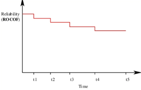
Fig 7: Step Function Model of Reliability Growth
Little wood and Verall’s model:
This model allows for negative reliability growth to reflect the fact that when a repair is carried out, it may introduce additional errors. It also models the fact that as errors are repaired, the average improvement to the product reliability per repair decreases.
Key takeaway:
References: