Unit - 2
Basic Architectural Framework
The ability of wireless sensor nodes to communicate through a wireless network is one of its most appealing features. Mobile applications can be supported, nodes can be deployed in flexible ways, and nodes can be placed in regions that would normally be inaccessible to wired nodes. It is feasible to reorganize node placement after deployment in order to provide optimal coverage and connection, and this rearrangement can be done without disturbing the structure or process that the nodes monitor.
Wireless communication, on the other hand, faces some serious problems. Restricted bandwidth, limited transmission range, and poor packet delivery performance due to interference, attenuation, and multipath scattering are just a few of the issues. Understanding the features of these difficulties, as well as some of the mitigating methods already in place, is critical to addressing them.
2.1.1 Basic Components
The transmitter, channel, and receiver are the three main components of a digital communication system. Because wireless sensor nodes in a wireless sensor network are close to one another, short-range communication is of relevance.
A block diagram of a digital communication system is shown in Figure. One or more sensors are represented by the communication source, which generates a message signal, which is an analog signal. The signal is a low-frequency baseband signal with dominant frequency components close to zero. To be processed by the processor subsystem, the message signal must be transformed to a discrete signal (discrete in both time and amplitude).
To ensure that no information is lost during the conversion, the signal must be sampled at least at Nyquist rate. The discrete signal is transformed to a binary stream after sampling. This is referred to as source encoding. It's critical to use an effective source-coding strategy in order to meet the channel's bandwidth and signal power requirements. One approach to do this is to define a probability model for the information source, in which the length of each information symbol is determined by its likelihood of occurrence.
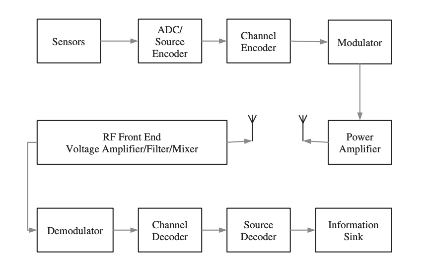
Fig 1: Components of a digital communication system
The following phase is channel encoding, which aims to make the transmitted signal noise and interference resistant. Furthermore, in the event of signal corruption, it allows for the detection of a mistake and the recovery of the original data. The transmission of symbols from a preset codebook and the transmission of redundant symbols are the two main ways.
2.1.2 Source and Channel Encoding
An analog signal is converted into a digital sequence using a source encoder. Sampling, quantification, and encoding are all part of the process.
Consider the following scenario: a sensor generates an analog signal that may be written as s (t). The analog-to-digital converter (ADC) with a resolution of Q distinct values will sample and quantize s(t) during the sampling process. As a result, a sample sequence S = (s[1], s[2],..., s[n]) is generated. The quantization error is the difference between the sampled s[j ] and its analog value at time tj. The quantization error fluctuates with the signal over time and can be described as a random variable with a probability density function, Ps (t).
The source encoder's goal is to convert each quantized element, s[j ], into a binary symbol of length r from a codebook, C. The codebook is called a Block Code if all of the binary symbols in it are the same length. However, the symbol length and sampling rate are not always consistent. As a result, most likely sample values are assigned short-sized symbols with high sampling rates, whereas less probable sample values are assigned long-sized symbols with low sampling rates. Figure illustrates the input–output relationship of a source encoder.

Fig 2: Input – output relationship of a source encoder
A codebook, C, can be uniquely decoded, if each sequence of symbols, (C(1), C(2), ...) can be mapped back to a corresponding value in S = (s[1], s[2], ..., s[n]). A binary codebook has to satisfy Equation (5.1) to be uniquely decoded.

where u denotes the codebook's size and li denotes the codeword's size (i).
If each symbol sequence can be extracted (decoded) from a stream of symbols without taking into account previously decrypted symbols, a codebook can be decoded instantly. This will be allowed if and only if a symbol in the codebook does not exist, such that the symbol a = (a1, a2,..., am) is not a prefix of the symbol b = (a1, a2,..., am) (b1, b2, ..., bn), where m<n and ai = bi, ∀i = 1, 2, ..., m within the same codebook.
Channel Encoding
A channel encoder's principal function is to generate a noise-resistant data sequence and to provide error detection and forward error correction techniques. Forward error correction is expensive in simple and low-cost transceivers, so the duty of channel encoding is confined to packet transmission error detection.
The size and rate of signal transmission are limited by the physical channel. These limitations are depicted in the diagram. The Shannon–Hartley theorem states that a channel's ability to send a message without error is given as:

where C denotes the channel capacity in bits per second, B denotes the channel bandwidth in hertz, S is the average signal power across the entire bandwidth in watts, and N denotes the average noise power over the entire bandwidth in watts.
According to the above equation, data should be transferred at a rate that is less than the channel's capacity to avoid errors. It also shows how increasing the signal-to-noise (SNR) ratio can increase channel capacity. The equation indicates two distinct reasons why errors may occur during transmission:
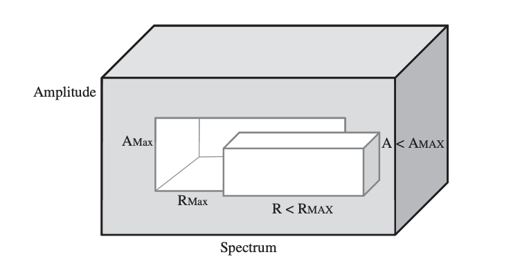
Fig 2: Stochastic model of a channel
Types of Channels
● Binary Symmetric Channel
A binary symmetric channel (BSC) is a channel type that allows for the transmission of bits of information (0 and 1). With a probability of p, the channel transmits a bit of information correctly (whether 0 or 1) and erroneously (by flipping 1 to 0 and 0 to 1) with a probability of 1 p. Figure shows an example of such a model.

Fig 3: A binary symmetric channel model
The following are the conditional probabilities for correct and incorrect transmissions:


As a result, the channel matrix of a binary symmetric channel is:

Binary Erasure Channel
There is no guarantee that the transmitted bit of information will be received at all in a binary erasure channel (BEC) (correctly or otherwise). As a result, the channel is classified as having a binary input and a ternary output. The likelihood of erasure is p, but the probability of receiving the information correctly is 1 p. The likelihood of a mistake in an erasure channel is zero. A binary erasure channel is shown in the diagram.
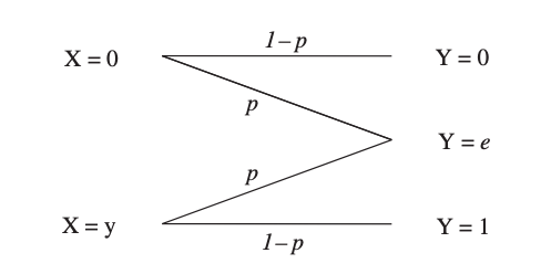
Fig 4: A stochastic model of a binary erasure channel
For a binary erasure channel, the channel matrix is:

According to equation, a bit of data is either effectively conveyed with P (1|1) = P (0|0) = 1 p or completely deleted by the channel with a probability of p. The probability that 0 is received by transmitting 1 or vice versa is 0.
2.1.3 Modulation
Modulation is the process of changing the parameters of a carrier signal (amplitude, frequency, and phase) in response to the message (baseband) signal. Modulation offers a number of benefits:
● The message signal will become noise-resistant,
● The channel's spectrum will be more efficiently utilized, and
● Signal recognition will be straightforward.
A baseband signal is used to transmit the message. That is to say, the major frequency components are close to zero. If this signal were to be delivered over a wireless link without any sort of modulation, the receiver antenna would need to be around one-fourth the wavelength of the signal. This is a very long antenna, and using one on a wireless device is unfeasible.
The message signal can also be superimposed on a bandpass carrier signal with a wavelength substantially smaller than the baseband signal. Sinusoidal carrier signals are utilized for modulation for a variety of reasons.
An amplitude modulation can be theoretically defined as follows, assuming both the carrier and modulating signals are analog sinusoidal signals:

In other words, the modulating signal, sm, affects the amplitude of sc(t) (t). Assume that the two signals are in phase (m = c = 0) to simplify the analysis, then the following Equation becomes:

The preceding Equation is reduced to: ejt = cos(t) + j sin(t) using Euler's formula (ejωt = cos(ωt) + j sin(ωt)).

The message signal is not a simple sinusoidal signal in reality. Instead, it's a B-band baseband signal, in which the amplitude and frequency shift as a function of time.
● Frequency and Phase Modulation
The carrier signal, sc(t), retains its amplitude in frequency modulation, but its frequency changes in response to the message signal, sm (t). It's crucial to keep the modulating signal's amplitude under control so that |sm(t)| 1. As a result, the modulated signal is defined as:

where  is the instantaneous variation of the local oscillator’s frequency. When this frequency variation is expressed as a function of the modulating signal, we get:

where fδ is the maximum frequency deviation of the carrier frequency, fc. Rearranging the terms in Equation yields:

The carrier's phase changes in step with the message signal in phase modulation.
● Amplitude Shift Keying
Until now, the modulated signal was thought to be analog. The modulated signal in digital communication is a binary stream.
The amplitude of an analog carrier signal is adjusted in accordance with a binary stream in amplitude shift keying, a digital modulation technique. The carrier signal's frequency and phase remain unaltered.
Amplitude shift keying can be accomplished in a variety of ways. The most straightforward method is to employ a on–off modulation scheme, as shown in Figure. The mixer (multiplier) provides an output that is the multiplication of two input signals, one of which is the message stream and the other is the output of the local oscillator, namely the sinusoidal carrier signal with a frequency of fc, as shown in Figure.
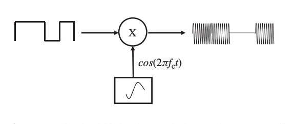
Fig 5: Amplitude shift-keying technique using an on-off switch.
Directly mixing a square wave (the bit stream) necessitates the use of a mixer with a large bandwidth, which is costly. A pulse-shaping filter can also be used to perform amplitude shift keying (PSF). The PSF reduces the square wave signal's high-frequency components and approximates it with a low-frequency signal, which modulates the carrier signal. This is displayed in Figure.

Fig 6: An amplitude shift-keying process using a pulse-shaping filter
● Frequency Shift Keying
In frequency shift keying, the carrier signal's frequency varies in response to the message bit stream. Because the message bit stream can be either 0 or 1, the carrier frequency can also be either 0 or 1. In frequency shift-keying modulation, a basic switching amplifier and two local oscillators with carrier frequencies f1 and f2 are shown in Figure. The message bit stream controls the switching amplifier.
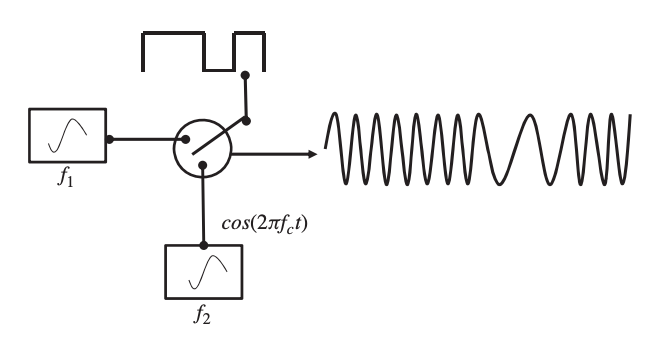
Fig 7: A frequency shift-keying modulation
● Phase Shift Keying
The phase of a carrier signal is modified according to the message bit stream in phase shift keying. When the bit stream goes from 1 to 0 or vice versa, the simplest type of phase shift keying is to make a 180-degree phase shift. Figure shows a phase shift-keying process in which a transition from 1 to 0 results in a phase shift of 180◦.

Fig 8: A phase shift-keying modulation process
The modulation process requires a local oscillator, an inverter, a switching amplifier, and a PSF. The inverter is responsible for inverting the carrier signal by 180◦
2. Quadratic Amplitude Modulation
A single message source has been used to modify a single carrier signal up to this point. This, however, is insufficiently effective. To fully use the bandwidth of a channel, orthogonal signals can be used. When two amplitude-modulated orthogonal carriers are joined as a composite signal in the QAM process, the bandwidth efficiency is doubled compared to standard amplitude modulation.
In digital systems, QAM is utilized in conjunction with pulse amplitude modulation (PAM), particularly in wireless applications. The modulated bit stream is split into two parallel substreams, each modulating the two orthogonal carrier signals independently.
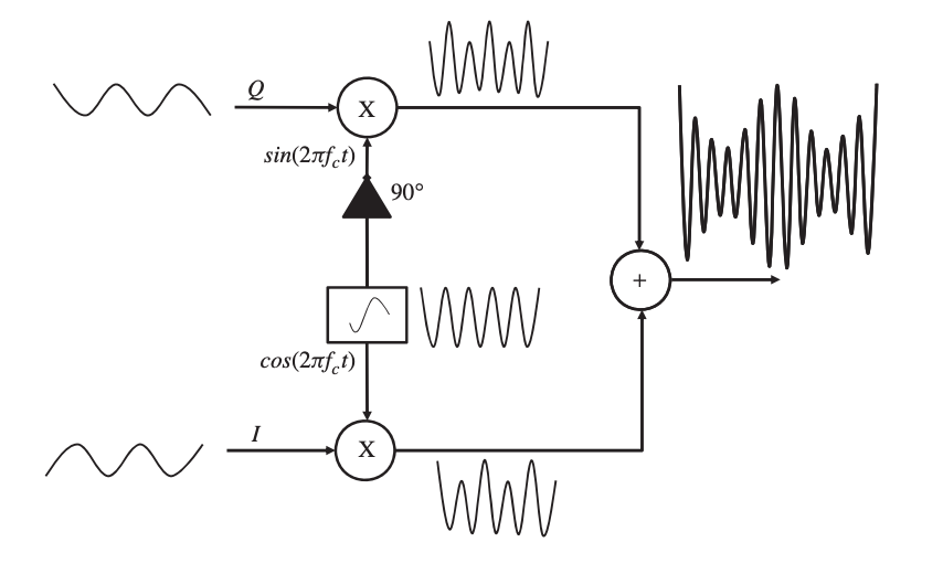
Fig 9: A quadratic amplitude modulation process
2.1.4 signal Propagation
Because wireless sensor networks operate in the license-free ISM spectrum, they must share the spectrum with and accept interference from devices that do the same – such as cordless phones, WLAN, Bluetooth, microwave ovens, and so on.
The effect of interference is ignored in a simple channel model, which considers the ambient noise to be the most important component affecting the transmitted signal. Furthermore, the noise can be described as an additive white Gaussian noise (AWGN) with a constant spectral density and a normal amplitude distribution over the full operational spectrum. The noise alters the magnitude of the transmitted signal in this model.
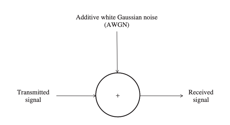
Fig 10: An additive white Gaussian noise channel
When it comes to dealing with noise, there are two options. First, the received power can be increased until the signal-to-noise ratio is much higher and the channel becomes noise agnostic. Second, a spread spectrum approach can be used to distribute the energy of the transmitted signal over a larger effective bandwidth.
A variety of parameters on both the transmitter and the receiver can be tweaked to optimize the received power. The relationship between received and transmitted power can be stated as shown in Figure.

Fig 11: Relationship between the transmitted power and the received power
Assume that the power amplifier, which is the last stage in the transmitter before the electric signal is transformed into electromagnetic waves, outputs a constant transmission power, Pt, to broadcast the signal across a distance of ρ. The relationship between the antenna gain of the transmitter, gt, and the effective area of the antenna, At, is given as:

where λ is the wavelength of the carrier signal.
The transmitted signal is received at the receiver's end, and the received power is a function of the distance, the path loss index, and the antenna gain and effective area of the receiver.
Key takeaway
Because the wireless medium must be shared by different network devices, a means to manage access to the medium is required. The data connection layer, the second layer of the OSI reference model, is responsible for this task. This layer is further separated into the logical link control layer and the medium access control layer, according to the IEEE 802 reference model (also shown in Figure).
The MAC layer sits on top of the physical layer, giving it complete control over the media. The MAC layer's primary responsibility is to determine when a node can access a shared medium and to handle any potential conflicts between competing nodes. It's also in charge of fixing communication faults at the physical layer, as well as other tasks including framing, addressing, and flow management.
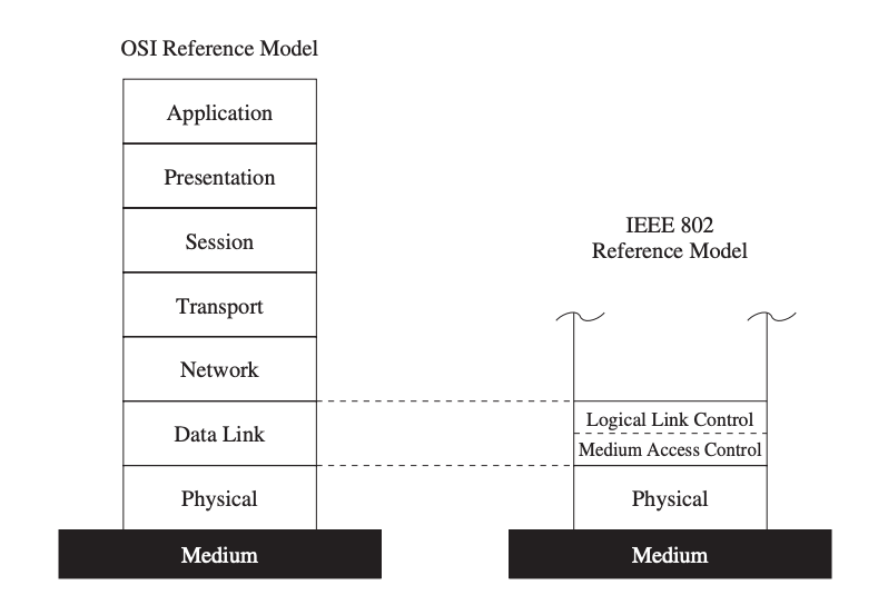
Fig 12: The MAC layer in the IEEE 802 reference model
Wireless MAC Protocols
While these protocols may not be ideal for wireless sensor networks, they do present fundamental concepts, many of which may be found in protocols designed expressly for sensor networks and their limitations.
Carrier Sense Multiple Access
The notion of CSMA is used in many contention-based protocols for wireless sensor networks. The primary difference between CSMA and ALOHA is that in CSMA, nodes first sense the medium before transmitting. In ALOHA, nodes first detect the medium before transmitting. As a result, the number of collisions is reduced. When a wireless node detects that the medium is idle in non-persistent CSMA, it is allowed to send data immediately.
If the media is busy, the node executes a backoff operation, which means it waits a certain amount of time before transmitting again. A node desiring to transmit data constantly observes the medium for activity in 1-persistent CSMA, on the other hand. The node transmits its data as soon as the medium is detected to be idle.
CSMA/CA (CSMA with Collidation Avoidance) is a CSMA variant that tries to increase performance by avoiding collisions. When nodes detect the medium in CSMA/CA, they do not immediately access the channel if it is discovered to be idle. Instead, a node waits for DCF interframe space (DIFS) plus the random backoff value, which is a multiple of the slot size.
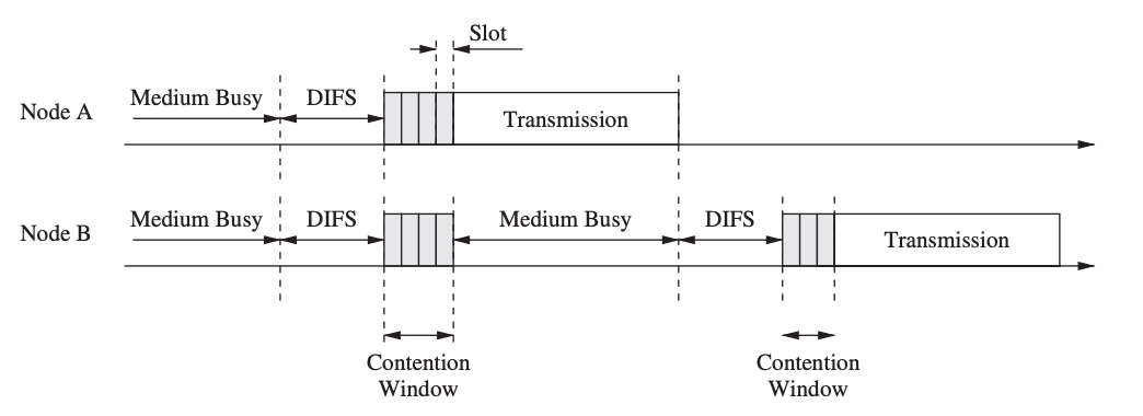
Fig 13: Medium access using CSMA/CA
Multiple Access with Collision Avoidance (MACA) and MACAW
Other collision avoidance techniques, such as MACA, use a dynamic reservation mechanism like ready-to-send (RTS) and clear-to-send (CTS) control packets (Karn 1990). A sender device uses RTS to communicate that it wants to deliver a data packet to a specific receiver. The receiver responds with a CTS control message if the RTS comes without collision and the receiver is ready to accept the packet.
If a sender does not get a CTS in response to an RTS, the sender will attempt again later. If, on the other hand, the CTS message is received, the channel reservation is complete. Other nodes that hear the RTS or CTS message are aware that a data transfer is about to take place, and they wait before attempting to reserve the channel. This wait time in MACA can be determined by the size of the data transmission, which can be specified in the RTS and CTS messages. By reserving the medium for data transfers, MACA addresses the hidden terminal problem and minimizes the amount of collisions.
When a packet is correctly received in MACAW (MACA for Wireless LANs), the receiver responds with an acknowledgment (ACK) control message, allowing other nodes to realize that the channel is available again and increasing transmission reliability.
MACA By Invitation
The MACA By Invitation (MACA-BI) Protocol adds to this by allowing a destination device to initiate data transfers by sending a Ready To Receive (RTR) packet to the source. The data message is then returned by the source. MACA-BI reduces overhead (raising theoretical maximum throughput) when compared to MACA, but it is dependent on the destination knowing when to receive data.
Source nodes can include an optional field in the data message to indicate the number of queued messages, indicating to the destination that further RTS packets will be needed.
IEEE 802.11
The 802.11 wireless LAN standard, issued by the Institute of Electrical and Electronics Engineers (IEEE) in 1999, specifies the physical and data link levels of the OSI model for wireless connectivity. Because of its widespread use and popularity, this section briefly describes some of the properties of this set of protocols. IEEE 802.11 is also known as "Wireless Fidelity" (Wi-Fi), a Wi-Fi Alliance certification that ensures compatibility between hardware devices that use the 802.11 standard.

Fig 14: IEEE 802.11 medium access control
IEEE 802.11 is available in two modes: point coordination function (PCF) and distributed coordination function (DCF). Communication between devices occurs in the PCF mode through a central entity known as an access point (AP) or a base station (commonly referred to as the managed mode). Devices communicate directly with each other in the DCF mode.
IEEE 802.11 is based on CSMA/CA, which means that before a node transmits, it first detects activity in the medium. The node is authorized to broadcast if the medium has been idle for at least the DCF interframe space (DIFS). Otherwise, a backoff mechanism is used to defer transmission to a later time. This method picks a number of time slots to wait for at random and saves the value in a backoff counter.
IEEE 802.15.4 and ZigBee
Low-power devices operating in the 868 MHz, 915 MHz, and 2.45 GHz frequency ranges are covered by the IEEE 802.15.4 standard. This standard supports data speeds of 20, 40, and 250 kbps, which are rather low when compared to other protocols like IEEE 802.11a (e.g., IEEE 802.11a offers data rates of up to 54 Mbps).
The ZigBee Alliance worked on a low-cost communication system with low data rates and low power consumption before this standard was created. After the IEEE and the ZigBee Alliance merged, ZigBee became the commercial name for the IEEE 802.15.4 technology. There are two topology modes in the standard: star and peer-to-peer. All communication occurs through the Personal Area Network (PAN) coordinator in the star topology, which is analogous to Bluetooth.
Devices can communicate directly with each other in a peer-to-peer manner. They must, however, first establish a relationship with the PAN coordinator before engaging in peer-to-peer communication. There are two sorts of modes in the star topology: synchronized (or beacon-enabled) mode and unsynchronized mode. The PAN coordinator transmits beacon messages for synchronization and management purposes in the synchronized mode.
2.2.1 Characteristics of MAC Protocols in Sensor Networks
The majority of MAC protocols are designed for fairness, which means that everyone should receive an equal quantity of resources (access to the wireless medium) and no one should be treated differently. Because all nodes in a WSN work together to achieve a common goal, fairness is less of an issue. Instead, wireless nodes are primarily concerned with energy consumption, and sensing applications may place a higher importance on low latency or high dependability than on fairness.
The following are the primary characteristics and design goals for WSN MAC protocols.
● Energy Efficiency
Because sensor nodes rely on finite energy sources (batteries), MAC protocols must be energy-efficient. Because MAC protocols have complete control over the wireless radio, their design can greatly reduce a sensor node's overall energy needs. Dynamic power management (DPM) is a typical strategy for conserving energy in which a resource can be moved between multiple operational modes such as active, idle, and sleep.
The active mode can gather together numerous various modes of operation, such as transmitting and receiving, for resources such as the network. Most transceivers transition between transmit, receive, and idle modes without power management, while the power consumption of the receive and idle modes is often similar.
● Scalability
Many wireless MAC protocols were created with infrastructure-based networks in mind, where access points or controller nodes arbitrate channel access or perform other centralized coordination and administration tasks.
Without centralized coordinators, most wireless sensor networks (WSNs) rely on multi-hop and peer-to-peer communications, and they can have hundreds or thousands of nodes. As a result, MAC protocols must be capable of allowing for effective resource utilization while avoiding unacceptable overheads, especially in very large networks.
● Adaptability
A WSN's ability to self-manage, or adapt to changes in the network, such as changes in topology, network size, density, and traffic characteristics, is a crucial feature. A WSN's MAC protocol should be able to adapt gracefully to such changes without incurring considerable expense.
This condition often supports dynamic protocols, i.e. protocols that make medium access decisions depending on current demand and network state. Due to adaptations of such assignments that may influence many or all nodes in the network, protocols with fixed assignments (e.g., TDMA with fixed-size frames and slots) may incur enormous overheads.
● Low Latency and Predictability
Many WSN applications have timeliness requirements, which means sensor data must be gathered, aggregated, and transmitted within a particular amount of time. Sensor data must be supplied to monitoring stations in a timely manner in a network that monitors the spread of a wildfire, for example, to provide accurate information and quick responses.
The MAC protocol is one of many network activities, protocols, and procedures that contribute to the delays experienced by such data. In a TDMA-based protocol, for example, a large frame size and a small number of slots given to a node might result in delays before crucial data can be carried over the wireless medium.
Nodes may be able to access the wireless medium faster in a contention-based protocol, but collisions and the consequent retransmissions cause delays. The MAC protocol chosen can also affect how predictable the experienced delay is, as indicated in higher latency boundaries, for example.
● Reliability
Finally, most communication networks have a requirement for reliability.
By identifying and recovering from transmission faults and collisions, the MAC protocol can contribute to greater reliability (e.g.using acknowledgments and retransmissions). Many link-layer protocols are concerned about reliability, especially in wireless sensor networks where node failures and channel problems are common.
2.2.2 Contention-Free MAC Protocols
Contention-free or schedule-based MAC techniques aim to prevent collisions and message retransmissions by allowing only one sensor node to access the channel at any given time. This, of course, requires a pristine medium and environment, with no other competing networks or misbehaving devices that could cause collisions or even jam a channel. This section covers some of the most prevalent aspects of contention-free MAC protocols for wireless sensor networks, as well as a few illustrative examples.
Characteristics
Contention-free protocols allocate resources to specific nodes to ensure that only one node can use a resource (for example, access to the wireless medium). This method reduces sensor node collisions, revealing a number of useful properties.
To begin with, a set allocation of slots allows nodes to precisely specify when they must activate their radio for data transmission or reception. The radio (or even the entire sensor node) can be switched into a low-power sleep mode during all other slots. As a result, common contention-free methods provide an energy efficiency benefit.
Fixed slot allocations also set upper boundaries on the delay that data may incur on a node in terms of predictability, making it easier to provide delay-bounded data delivery.
Traffic-Adaptive Medium Access
When compared to standard TDMA and contention-based solutions, the Traffic-Adaptive Medium Access (TRAMA) protocol (Rajendran et al. 2003) is a contention-free MAC protocol that strives to boost network throughput and energy efficiency. It determines when nodes are authorized to transmit using a distributed election process based on information about traffic at each node.
This avoids assigning slots to nodes who have no traffic to send (leading to increased throughput) and allows nodes to decide when they can stop listening to the channel and become idle (increased energy efficiency).
TRAMA presupposes that the channel is time-slotted, with time divided into periodic random access periods (signalling slots) and scheduled-access intervals (transmission slots). The Neighbour Protocol (NP) is used to transport one-hop neighbors' information to neighbouring nodes during random-access periods, allowing them to get consistent two-hop topology information.
Y-MAC
Y-MAC is another protocol that uses TDMA-based media access for multiple channels. Y-MAC splits time into frames and slots in the same way as TDMA does, with each frame containing a broadcast and unicast period. At the start of a broadcast period, every node must wake up, and nodes compete for access to the media during this time. If no broadcast messages are received, each node turns off its radio and waits for its first assigned slot in the unicast period.
For receiving data, each slot in the unicast period is allotted to only one node. Because each node samples the medium only in its own receive time intervals, this receiver-driven approach can be more energy-efficient under light traffic situations. This is especially relevant for radio transceivers, since the cost of receiving energy is higher than the cost of broadcasting (e.g., due to sophisticated despreading and error correction techniques).
In Y-MAC, medium access relies on synchronous low-power listening. Multiple senders' contention is resolved in the contention window, which appears at the start of each slot. The node wakes up after this time and senses the medium for activity for a set length of time. If the medium is free, the node transmits a preamble to inhibit competing transmissions until the end of the contention window. At the end of the contention window, the receiver wakes up to await packets in its allotted slot.
DESYNC-TDMA
DESYNC is a self-organizing de-synchronization algorithm that is used to construct a collision-free TDMA-based MAC protocol (dubbed DESYNC-TDMA). This MAC protocol addresses two flaws in standard TDMA: it doesn't require a global clock and it automatically adjusts to the number of participating nodes to ensure that all available bandwidth is used.
De-synchronization is a valuable basis in a range of sensor applications for periodic resource sharing. Sensors sampling a common geographic region, for example, can de-synchronize their sampling schedules such that the monitoring task's requirements are evenly spread across the sensors. De-synchronization is employed in DESYNC to implement TDMA-style medium access.
Low-Energy Adaptive Clustering Hierarchy
For wireless sensor networks, the Low-Energy Adaptive Clustering Hierarchy (LEACH) protocol combines TDMA-style contention-free communication with a clustering algorithm. A cluster is made up of a single cluster head and any number of cluster members, all of whom communicate solely with the cluster head.

Fig 15: Operation and communication structure of LEACH
Clustering is a popular sensor network strategy because it allows for data aggregation and in-network processing at the cluster head, reducing the quantity of data that must be transferred to the base station. LEACH works in rounds, which are divided into two phases: setup and steady-state.
● Setup Phase
Cluster heads and communication schedules within each cluster are chosen during the setup process. The cluster head's energy consumption will be much higher than those of other sensor nodes because it is responsible for coordinating cluster activity and relaying data to the base station. To distribute the energy load uniformly, LEACH rotates the cluster head responsibilities among sensor nodes.
● Steady-State Phase
A sensor node communicates exclusively with the cluster head and is only authorized to transmit data during the time slots specified in the cluster head's schedule. The cluster head is then responsible for forwarding sensor data from one of its sensor nodes to the base station. To save energy, each cluster member sends the smallest amount of data possible to the cluster head and turns off the wireless radio between slots. In order to acquire sensor data from its cluster members and connect with the base station, the cluster head, on the other hand, must remain awake at all times.
Lightweight Medium Access Control
The Lightweight Medium Access Control (LMAC) protocol is TDMA-based, which means that time is divided into frames and slots, with each slot belonging to one node. Rather than relying on a central manager to allot slots to nodes, nodes use a distributed mechanism to do so.
Each node sends a message that is made up of two parts: a control message and a data unit. The identity of the time slot controller, the distance (in hops) between the node and the gateway (base station), the address of the intended receiver, and the length of the data unit are all included in the fixed-size control message.
2.2.3 Contention-Based MAC Protocols
Contention-based MAC protocols don't use transmission schedules to address contention, instead relying on other means. When opposed to other schedule-based strategies, the main advantage of contention-based techniques is their simplicity. Schedule-based MAC protocols, for example, must record and maintain schedules or tables indicating transmission order, whereas most contention-based protocols do not involve saving, maintaining, or sharing state information.
Contention-based protocols can also adapt fast to changes in network topologies or traffic characteristics as a result of this. Due to idle listening and overhearing, contention-based MAC protocols often result in greater collision rates and energy expenditures. Contention-based approaches may also have concerns with fairness, since certain nodes may be able to get more frequent channel access than others.
Power Aware Multi-Access with Signaling
The Power Aware Multi-Access with Signalling (PAMAS) protocol's main goal is to minimize wasting energy due to overhearing. Because node C is node B's near neighbor, node B's transmission to node A is overheard by node C in Figure. As a result, receiving a packet destined for another node consumes energy at node C.
Furthermore, because C is within B's interference range, C will not be able to receive a frame from another node while B is transmitting. As a result, C can put its radio into a low-power sleep mode for the duration of B's transmission to save energy. This is especially beneficial in dense networks, when a node may be inside the interference ranges of a large number of other nodes.

Fig 16: Power consumption caused by unnecessary overhearing
Sensor MAC
The sensor MAC (S-MAC) protocol aims to save energy by reducing superfluous transmissions while also ensuring scalability and collision avoidance. S-MAC uses a duty-cycle technique, in which nodes alternate between a listen and a sleep state on a regular basis. Each node sets its own schedule, while it is preferable if nodes' schedules are synchronized so that they listen or sleep at the same time. Nodes that use the same schedule are deemed to be part of the same virtual cluster in this situation, but there is no real clustering and all nodes are allowed to connect with nodes outside their clusters.
Nodes use SYNC messages to communicate their schedules to their neighbors on a regular basis, so each node knows when any of its neighbors will be awake. If node A wants to connect with a neighbor B who operates on a different schedule, A must first wait for B to listen before initiating the data transfer. The RTS/CTS method is used to resolve medium contention.
A node first listens to the media for a specific amount of time in order to choose a schedule. When this node receives a schedule from a neighbor, it adopts it as its own, and it becomes a follower.
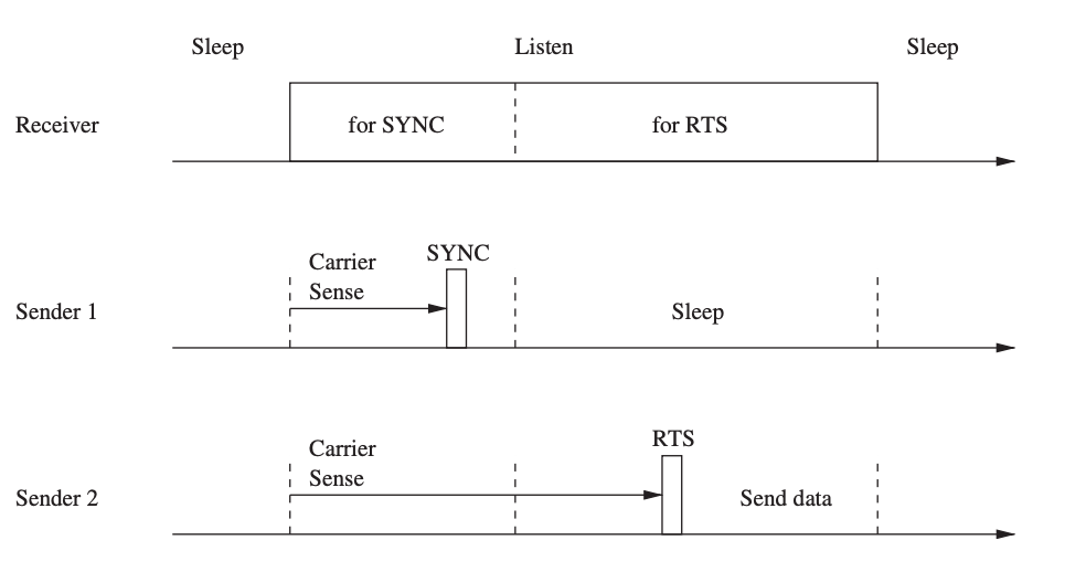
Fig 17: S-MAC timing and messaging relationships
Timeout MAC
S-listening MAC's period is set in stone, which means that if there isn't much traffic, it will waste electricity. However, if traffic is high, the fixed length may not be sufficient. As a result, the Timeout MAC (T-MAC) protocol is a version of the S-MAC protocol that has an active time that varies according to traffic density.
When no communication is detected, nodes wake up at the start of a slot to listen for activity for a short period of time before returning to sleep. When a node transmits, receives, or overhears a message, it remains alert for a short amount of time after the message transfer is completed to see whether there is any additional traffic. This short timeout interval allows a node to go into sleep mode as soon as feasible. As a result, a node's awake times will rise as traffic increases, and they will be very brief if traffic is light.
Pattern MAC
Another TDMA-style protocol that employs frames and slots is the Pattern MAC (PMAC) protocol (Zheng et al. 2005), which changes its sleep periods based on its own traffic and the traffic patterns of its neighbors. PMAC, in comparison to S-MAC and T-MAC, minimizes the energy expenditures of idle listening by allowing devices to turn off their radios for long periods of time when they are not in use.
Nodes utilize patterns to define their tentative sleep and wake timings. A pattern is a string of bits, each bit representing a time slot and signaling whether a node intends to sleep (bit is 0) or be awake (bit is 1). (bit is 1).
In summary, PMAC is a simple tool for creating timetables that adjust to the amount of traffic in a given area. When traffic loads are low, a node might spend a significant amount of time in the sleep state, conserving energy. Collisions during the PETF, on the other hand, may prohibit nodes from receiving pattern updates from all neighbors, even though other nodes may have gotten them. This causes inconsistencies in the schedules of nodes in a neighborhood, which can lead to more collisions, wasted transmissions, and idle listening.
Routing-Enhanced MAC
The Routing-Enhanced MAC (RMAC) protocol is another example of an energy-saving technology that uses duty cycles. It aims to enhance end-to-end latency and contention avoidance when compared to S-MAC. RMAC's central notion is to coordinate the sleep/wake times of nodes along the sensor data pipeline so that a packet can be transmitted to its destination in a single operational cycle. This is accomplished by sending a control frame along the path to notify nodes about the forthcoming packet, letting them learn when to be awake to accept and forward it.
The SYNC phase, the DATA period, and the SLEEP period are the three parts of an operating cycle that RMAC divides into. Nodes synchronize their clocks during the SYNC phase to ensure that they maintain appropriate precision. The DATA period is used to notify and start the packet transmission process on its way to its destination. The sender waits for a randomly chosen period of time plus an additional DIFS period during which it senses the medium during the DATA period, which is contention-based.
Data-Gathering MAC
The Data-Gathering MAC (DMAC) protocol takes advantage of the fact that many wireless sensor networks use convergecast as a communication pattern, which means that data from sensor nodes is collected at a central node in a data-gathering tree (the "sink"). DMAC's purpose is to send data with minimal latency and good energy efficiency along the data gathering tree.
The duty cycles of nodes along the multi-hop path to the sink are "staggered" in DMAC; nodes wake up in a chain reaction fashion. Figure shows an example of a data-gathering tree and the staggered wakeup technique to explain this concept.

Fig 18: Data-gathering tree and convergecast communication in DMAC
Nodes cycle through the stages of sending, receiving, and sleeping. During the sending state, a node transmits a packet to the route's next hop node and waits for a response (ACK). The next hop node is in the receiving state at the same moment, followed by a sending state to forward the packet to the next hop (unless the node is the packet's destination).
Preamble Sampling and WiseMAC
WiseMAC is a MAC protocol that addresses the energy consumption of downlink communication in infrastructure-based sensor networks, that is, communication between a base station and sensor nodes. WiseMAC uses the preamble sampling approach to prevent energy waste from idle listening.
The receiving node is alerted by the base station transmitting a preamble before the actual data delivery. With a fixed period Tw, all sensor nodes sample the medium (listen to the channel), but with separate and consistent relative sampling schedule offsets. A sensor node listens until the media becomes idle or a data frame is received if the medium is busy.
The preamble is the same length as the sampling period, ensuring that the receiver is awake when the data portion of the packet is received. This method allows energy-constrained sensor nodes to turn off the radio while the channel is idle without losing packets.

Fig 19: Preamble sampling
Receiver-Initiated MAC
The Receiver-Begun MAC (RI-MAC) protocol is another contention-based method, in which a transmission is always initiated by the data receiver. Each node wakes up at regular intervals to check for incoming data packets. That is, a node checks if the medium is idle immediately after turning on its radio and, if it is, transmits a beacon message declaring that it is awake and ready to receive data.
A node with untransmitted data remains awake and listens for a beacon from its intended receiver. The sender instantly transmits the data after receiving this beacon, which is acknowledged by the recipient with another signal.
The beacon, in other words, has two functions: it encourages new data transmissions and it acknowledges prior data broadcasts. After a specified period of time passes without any arriving data packets following the beacon broadcast, the node falls back to sleep.
A receiver's beacon frames are used to coordinate broadcasts when there are numerous competing senders. The backoff window size (BW) is a field in the beacon that indicates the window over which to choose a backoff value. Senders instantly begin transmission if the beacon does not contain a BW (the initial beacon broadcast after waking up does not contain a BW).
2.2.4 Hybrid MAC Protocols
Some MAC protocols do not easily fit into either the schedule-based or contention-based categories, but instead exhibit traits from both. For example, they may attempt to reduce the number of collisions by relying on features found in periodic contention-free medium access protocols while utilizing the flexibility and low complexity of contention-based protocols. Describes some representative hybrid protocol examples.
Zebra MAC
The Zebra MAC (Z-MAC) protocol (Rhee et al. 2005) employs frames and slots to offer contention-free access to the wireless medium, comparable to TDMA-based protocols. Z-MAC, on the other hand, permits nodes to use CSMA with prioritized backoff periods to use slots they don't control. As a result, in low-traffic settings, Z-MAC emulates a CSMA-based approach, whereas in high-traffic scenarios, it emulates a TDMA-based approach.
When a node first starts up, it goes through a setup phase that allows it to find its neighbors and receive its TDMA frame slot. Every node sends out a message providing a list of its neighbors on a regular basis. A node learns about its 1-hop and 2-hop neighbors through this method.
This data is fed into a distributed slot assignment mechanism, which assigns time slots to each node, guaranteeing that no two nodes in the same 2-hop neighborhood are assigned the same slot. Furthermore, Z-MAC enables nodes to choose the periodicity of their allotted slots, with different nodes having varying time frames (TF).
The benefit of this strategy is that a maximum slot number (MSN) does not need to be propagated throughout the entire network, and the protocol can alter slot allocations locally.
Mobility Adaptive Hybrid MAC
Some or all nodes in many sensor networks may be mobile, posing substantial issues for the design of a MAC protocol. The Mobility Adaptive Hybrid MAC (MH-MAC) protocol presents a hybrid solution in which static nodes use a schedule-based approach while mobile nodes utilize a contention-based approach.
While determining a TDMA-style schedule for static nodes is simple, this is not the case for mobility nodes. As a result, MH-MAC allows mobile nodes entering a neighborhood to employ a contention-based method instead of adding delays to the schedule.
A frame's slots fall into one of two groups in MH-MAC: static slots or mobile slots. To estimate its mobility and which type of slots it should use, each node uses a mobility estimation technique. The mobility estimation is based on the frequency of hello messages and the intensity of the received signal.
The greeting messages are always sent at the same transmit power, and the receiving nodes compare the signal intensities of subsequent messages to calculate the relative location displacement between themselves and their neighbors. At the start of each frame, a mobility beacon interval is supplied to distribute mobility information to neighbors.
In summary, MH-MAC combines the LMAC protocol's characteristics for static nodes with contention-based protocol features for mobile nodes. As a result, mobile nodes can instantly join a network without having to wait for setup or adaption. MHMAC, unlike LMAC, allows nodes to own several slots in a frame, increasing bandwidth usage and lowering latencies.
Key takeaway
Centric Routing, Proactive Routing, On-Demand Routing, Hierarchical Routing, Location-Based Routing, QoS-Based Routing Protocols
The network layer's main job is to find pathways from data sources to sink devices (e.g., gateways). All sensor nodes can connect directly with the sink device in the single-hop routing architecture l (left graph in Figure). The simplest approach is direct communication, in which all data travels a single hop to reach its destination. In practice, however, a single-hop communication model (right graph in Figure) is unworkable, and a multi-hop communication model is required. The network layer of all sensor nodes' important role in this situation is to find a path from the sensor to the sink via several other sensor nodes functioning as relays.
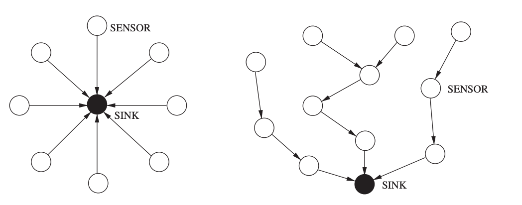
Fig 20: Single-hop routing model (left) versus multi-hop routing model (right)
Because of the inherent properties of WSNs, such as resource scarcity and the unreliability of the wireless medium, designing a routing protocol is difficult. For example, limited processing, storage, bandwidth, and energy capacity necessitate lightweight routing solutions, yet frequent dynamic changes in a WSN (e.g., topology changes due to node failures) necessitate adaptive and flexible routing solutions.
2.3.1 Routing Metrics
The restrictions and characteristics of wireless sensor networks and their applications vary greatly, which must be taken into account while designing a routing protocol. Most WSNs, for example, will be limited in terms of available energy, computing power, and storage capacity.
Sensor networks differ greatly in terms of scale, geographic coverage, and position awareness. In networks with heterogeneous nodes and node mobility, global addressing methods (such as IP addresses used on the Internet) may be unavailable or perhaps impossible. Finally, from the standpoint of the application, sensor data can be acquired in a variety of ways.
In time-driven systems (such as environmental monitoring), nodes send their collected sensor data to a sink or gateway device on a regular basis. Event-driven methods (for example, wildfire detection) need nodes to communicate their acquired data only when events of interest occur. Finally, in query-driven systems, the sink is responsible for requesting data from sensors when necessary. The design of a routing protocol is motivated by the resources available in the network and the needs of the applications, regardless of the network architecture utilized.
Commonly Used Metrics
● Minimum Hop
● Energy
● Quality-of-Service
● Robustness
2.3.2 Flooding and Gossiping
Flooding the entire network is an ancient and straightforward approach for disseminating information into a network or reaching a node at an unknown location. A sender node broadcasts packets to its immediate neighbors, who then rebroadcast the packets to their own neighbors until all nodes have received the packets or the packets have traveled the maximum number of hops.
If there is a path to the destination (and assuming lossless communication), the data is guaranteed to reach the target. Flooding has a lot of benefits, but it also has a lot of drawbacks, one of which is that it produces a lot of traffic.
As a result, precautions must be made to ensure that packets do not transit endlessly through the network. Maximum-hop counts, for example, are used to limit how many times a packet is transmitted. It should be large enough to reach all intended receivers, but small enough to avoid packets taking too long to travel over the network.
Flooding is complicated by a number of factor :
● Implosion
● Overlap
● Resource Blindness
2.3.3 Data-Centric Routing
In most sensor networks, the information generated by the sensor nodes is more essential than the sensor nodes themselves. As a result, rather than collecting data from specific sensors, data-centric routing strategies focus on retrieving and disseminating information of a specific sort or specified by certain features.
Sensor Protocols for Information via Negotiation
Sensor Protocols for Information through Negotiation (SPIN) is a group of flooding protocols that are based on negotiation, data-centric, and time-driven. In contrast to traditional flooding, SPIN nodes rely on two fundamental strategies to overcome flooding's shortcomings.
To avoid implosion and overlap, SPIN nodes communicate with their neighbors before transmitting data, allowing them to avoid sending unneeded data. To combat resource blindness, each SPIN node employs a resource manager to measure actual resource consumption, allowing them to adjust routing and communication behavior in response to resource availability. SPIN employs meta-data to explain the data collected by sensor nodes in a concise and comprehensive manner.
Directed Diffusion
Directed diffusion is a data-centric data distribution system that is also application-aware, in the sense that data generated by sensor nodes is named using attribute-value pairs. Directed diffusion's primary principle is that nodes seek data by transmitting interests for specific data. This interest dissemination creates network gradients that route sensor data to the intended receiver, while intermediate nodes along data channels can aggregate data from several sources to avoid redundancy and reduce the amount of transmissions.
Instead of using universally valid node identifiers, directed diffusion uses attribute-value pairs to specify a sensing task and direct the routing process. For example, a simple vehicle-tracking program could be described as follows:
type
type = vehicle // detect vehicle location
interval = 20 ms // send data every 20 ms
duration = 10 s // perform task for 10 s
rect = [-100, -100, 200, 200] // from sensors within rectangle
A task description, in other words, communicates a node's desire (or interest) in receiving data that matches the specified attributes. The data delivered in response to such interests is similarly named using attribute-value pairs.
Rumor Routing
While event flooding describes the process of propagating queries to all nodes in the network when no localization information is available to steer the query toward the appropriate sensors, query flooding describes the process of propagating queries to all nodes in the network when no localization information is available to steer the query toward the appropriate sensors. Rumor routing is a hybrid of directed diffusion and rumor routing that aims to incorporate the best of both strategies.
Each node in rumor routing has a list of its neighbors as well as an event table with forwarding information for all known events. When a node observes an event (i.e., a physical phenomena), the event is recorded in this table (with a distance of zero) and an agent with a specific probability is formed (i.e., not all events may result in an agent generation). This agent is a long-lived packet that travels the network to inform faraway nodes about this and other events it encounters along the way. When an agent arrives to a node, the node can update its own table using the content of the agent.
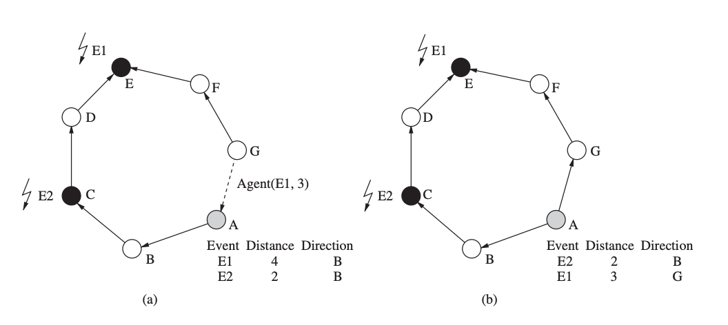
Fig 21: Rumor routing: (a) before the arrival of the agent notifying B of a shorter path to E1, (b) after the arrival of the agent
Gradient-Based Routing
Gradient-Based Routing (GBR) is a variation of directed diffusion in which a gradient is determined based on the number of hops to the sink. GBR, like directed diffusion, uses interests to capture a sink's desire to accept specific sorts of information, and gradients are established on each node during the flooding of these interests. Each interesting announcement message keeps track of how many hops it's taken since it left the sink.
This allows nodes in the network to calculate their distance to the sink (in terms of hops), which is referred to as a node's height in GBR. The gradient on the link between these two nodes is defined as the difference between a node's height and the height of its neighbor. Following that, a data packet is forwarded on the link with the greatest gradient.
Data from various pathways passing through a node may be merged. In GBR, nodes can create a Data Combining Entity (DCE), which is responsible for data compression in order to improve the network's resource efficiency. GBR also employs traffic dispersion techniques to better balance traffic across the network. When there are two or more future hops with the same gradient, each node in the stochastic spreading scheme chooses the next hop at random.
2.3.4 Proactive Routing
Routing protocols that are proactive (or table-driven) create paths before they are required. The fundamental benefit of this strategy is that routes are available anytime they are needed, and there are no delays in finding routes, as with on-demand routing protocols. The overheads associated in developing and maintaining potentially very large routing tables, as well as the risk of routing errors due to stale information in these tables, are the key drawbacks.
Destination-Sequenced Distance Vector
The DSDV routing protocol is a tweaked variant of the original Distributed Bellman-Ford algorithm. Every node I in a distance-vector method keeps a list of distances dxij for each destination x via each neighbor j. If dikx = min dx ij, node I chooses node k as the next step for packet forwarding. This data is saved in a routing table, along with a sequence number issued by the destination node to each entry. The sequence numbers are used to help nodes distinguish between old and new routes in order to avoid routing loops.
Each node updates the routing table on a regular basis, as well as whenever important new information becomes available. To share the content of its routing table, DSDV uses two sorts of packets. An incremental packet only provides information that has changed since the last complete dump, whereas a full dump contains all available routing information. Because incremental packets are often significantly smaller than entire dumps, DSDV's control overhead is reduced.

Fig 22: Example of a network with a moving node
Optimized Link State Routing
The Optimized Link State Routing (OLSR) protocol, which is based on the link state algorithm, is another proactive approach. Nodes in this approach broadcast topological information updates to all other nodes in the network on a regular basis, allowing them to get a comprehensive topological map of the network and quickly find pathways to any destination.
In the OLSR, every node employs neighbor sensing to identify its neighbors and notice changes in the node's environment. A node accomplishes this by broadcasting a HELLO message that provides the node's identity (address) as well as a list of all known neighbors. This list also indicates whether the link between the node and the neighbor is symmetric (both can receive each other's messages) or asymmetric (both can send and receive messages).
A node can learn about its two-hop neighborhood by collecting HELLO messages from its neighbors. Topological information must be flooded throughout the network in order to gather network-wide information. OLSR depends on multipoint relays (MPRs) to provide a more efficient manner of spreading such control information than the traditional flooding approach. In other words, a node chooses a set of symmetric neighbor nodes as MPRs, which is referred to as the MPR selection set.
2.3.5 On-Demand Routing
Reactive routing systems, in contrast to proactive routing protocols, do not find and maintain routes unless they are expressly requested and used. Knowing the identification or address of the destination node, a source node starts a route discovery process within the network, which ends when at least one route is found or all feasible routes have been investigated. The route is then maintained until it either breaks or the source no longer requires it.
Ad Hoc On-Demand Distance Vector
The Ad Hoc On-Demand Distance Vector (AODV) protocol is an example of an on-demand or reactive protocol. Unlike OLSR, nodes do not keep track of routing information or exchange routing tables on a regular basis. AODV uses a broadcast route discovery approach to establish route table entries at intermediate nodes dynamically.
When a source node needs to transmit data to another node for which it does not have routing information in its table, the AODV path discovery procedure is started. The source node accomplishes this by broadcasting a route request (RREQ) packet to its neighbors, which contains the source and destination addresses, a hop count value, a broadcast ID, and two sequence numbers.
When a source sends out a new RREQ packet, the broadcast ID is incremented, and it is used with the source's address to uniquely identify an RREQ. When a node with a current route to the given destination receives an RREQ packet, it reacts by sending a unicast route reply (RREP) message straight to the neighbor who sent the RREQ. Otherwise, the RREQ is rebroadcast to the neighbors of the intermediary node. A duplicate RREQ is discarded (identified by its source address and broadcast ID).

Fig 23: Path discovery process of AODV
Dynamic Source Routing
Similar to AODV, the Dynamic Source Routing (DSR) protocol (Johnson 1994) uses route discovery and maintenance algorithms. Each node in DSR keeps a route cache with entries that are constantly updated as new routes are learned. A node desiring to send a packet will first check its route cache to verify if it already has a route to the destination, similar to AODV. If no valid route is found in the cache, the sender launches a route discovery procedure by broadcasting a route request packet containing the destination's address, the source's address, and a unique request ID.
As a result, a request packet saves a route that includes all nodes it has visited. When a node receives a request packet and discovers that it contains its own address, it discards the packet and does not rebroadcast it. A node stores a cache of recently forwarded request packets, records their sender addresses and request IDs, and discards any request packets that are duplicated.
A request packet will have logged the whole path from the source to the destination whenever it arrives at the destination. In symmetric networks, the destination node can unicast a response packet containing the route information obtained back to the source using the same path as the request packet. In networks with asymmetric links, the destination can commence a route discovery procedure to the source, with the path from the source to the destination included in the request packet.
2.3.6 Hierarchical Routing
Hierarchical routing techniques use clustering of nodes to alleviate some of the shortcomings of flat routing protocols, namely scalability and efficiency. The primary notion underlying hierarchical routing is that sensor nodes only communicate with the cluster head, or the leader node in their own cluster. The sensor data is subsequently sent to the sink by these cluster heads, which may be more powerful and less energy-constrained devices than "normal" sensor nodes. Sensor nodes will incur substantially less communication and energy costs as a result of this technique, whereas cluster heads will see significantly more traffic than ordinary sensor nodes.
The selection of cluster heads, the construction of clusters, and modifications to network dynamics such as mobility or cluster head failures are all challenges in the design and operation of hierarchical routing protocols. Hierarchical solutions, as opposed to flat routing systems, may reduce collisions in the wireless medium and make duty cycling of sensor nodes easier, resulting in increased energy efficiency.
Clustering can help with routing, but it can also result in longer routes than many flat routing protocols. Because data from collocated sensors (which may monitor overlapping portions of the environment) is likely to transit via the same cluster head, clustering facilitates in-network aggregation of sensor data. Two clustering approaches are depicted in the diagram. The routing problem is reduced to the cluster formation problem when all cluster heads communicate directly with the sink node (left graph). A cluster-based routing protocol must construct multi-hop routes from all cluster heads to the sink when cluster heads do not directly connect with the sink (right graph).
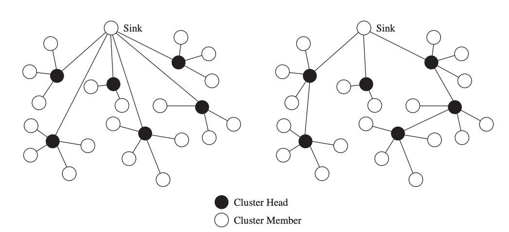
Fig 24: Clustering with single-hop connections to the sink (left) and clustering with multi-hop connections to the sink (right)
Nodes self-organize into hierarchies in the landmark routing technique, where a landmark is a node to which its neighbors within a particular number of hops know a path. Assume that nodes 2–6 contain routing information for node 1 in the left network of Figure. Nodes 7–11, on the other hand, do not have routes to node 1, hence node 1 is a landmark that can be seen from all nodes within a 2-hop distance. Node 1 becomes a landmark with a radius of 2. A landmark of radius n is a node I for which all other nodes within n hops contain routing information toward it.
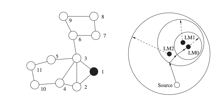
Fig 25: Definition of a landmark (left) and routing using a hierarchy of landmarks (right)
2.3.7 Location-Based Routing
In networks where sensor nodes can detect their position using a variety of localization techniques and algorithms, location-based or geographic routing can be used. Sensors make forwarding decisions based on geographic information rather than topological connectivity information. Packets are sent directly to a single destination, which is identified by its location, in unicast location-based routing. That is, a sender must be aware of both its own location and the destination's location.
This location can be retrieved by querying (for example, flooding a query to seek a response from the destination with the destination's location) or using a location broker, which is a service that maps node IDs to locations. The same packet must be spread to numerous destinations in broadcast or multicast location-based routing systems. Multicast methods take advantage of known destination locations to reduce unnecessary links and thus reduce resource consumption.
The identity of a sensor node is usually less relevant than its position, which means that data can be distributed to all nodes in a certain geographic region. This method is known as geocasting, and it can be used to direct queries to specific areas of interest rather than overwhelming the entire network, resulting in significant bandwidth and energy savings. When a packet arrives in the intended region, it must either be disseminated (multicast) to all nodes in the region or transmitted to at least one node in the region (anycast).
Unicast Location-Based Routing
The purpose of unicast location-based routing is to transmit a packet to a specific node at a known position to the sender. On each node, the routing protocol's job is to make a local forwarding decision so that a packet gets closer to its destination with each hop.
Figure shows an example of this simple operation, with broken circles indicating the forwarding nodes' transmission ranges and arrows indicating the packet's subsequent travel. In this greedy forwarding method, all that is required is that each node knows its own location as well as the locations of its neighbors, and that the source knows the destination's location.
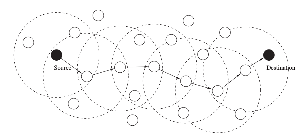
Fig 26: Unicast location-based routing
However, there are certain drawbacks to this strategy. Most notably, a packet may arrive at a node with no neighbors that could act as next hops, bringing the packet closer to its destination. Most location-based routing protocols address the difficulty of identifying and avoiding such blanks or holes. The remainder of this section discusses solutions to this problem using different typical unicast location-based routing technologies.
Multicast Location-Based Routing
The term "multicast" refers to the delivery of the same packet to several receivers at the same time. Using unicast routing, a simple way might deliver the packet to each receiver separately. This strategy, however, is wasteful in terms of resources since it does not take advantage of the fact that routes to various receivers may share paths.
Another method is to just flood the network, which assures that all recipients receive a copy of the packet but is quite resource intensive. Multicast routing is concerned with delivering the identical packet to all recipients as efficiently as possible by reducing the number of links that the packet must travel to reach all destinations. A popular method is to create a multicast tree with the packet source as the root node and the destinations as leaf nodes.
To keep track of all destinations for a given packet, the Scalable Position-Based Multicast (SPBM) protocol uses a group management mechanism. Instead of putting all destinations in the packet header, SPBM uses hierarchical group membership management to ensure that the technique is efficient even when there are a lot of them.
Geographic Multicast Routing (GMR) and Receiver Based Multicast (RBMulticast) are two further location-based multicast technologies. GMR employs a low-computing-overhead heuristic neighbor selection approach that produces efficient routes based on a cost-over-progress metric. The number of selected forwarding nodes divided by the progress made toward all destinations yields this measure (i.e., the total remaining distance from the neighbors to the destinations minus the total distance from the forwarding node to all destinations).
Geocasting
In many wireless sensor networks, propagating information to all or some nodes within a defined geographic region is preferred. For many sensor network applications, this is a natural approach, especially when the exact placement of individual sensors is uncertain.
In query-based networks, for example, instead of sending the same question to different individual sensors, the same query can be spread to several sensors monitoring a specified geographic area. The routing problem is then broken down into two parts: (1) propagating a packet near the target region, and (2) distributing a packet within the target region.
Although no specific location of a sensor node near or within the target region may be known, the first difficulty can be addressed using methodologies similar to unicast location-based routing as previously discussed. If a packet only needs to reach one node inside the target region, the protocol is considered successful once it reaches at least one node within the region. However, if every node in the region needs a copy of the packet, the second difficulty can be solved using techniques similar to broadcasting. As a result, geocasting to many receivers combines unicast and broadcast geographic routing.
2.3.8 QoS-Based Routing Protocols
Although most routing and data dissemination protocols aim for some type of Quality-of-Service (QoS), certain techniques proposed for sensor networks expressly target one or more QoS routing metrics. For example, minimum hop routing protocols try to achieve low latencies by employing "short" connections.
The purpose of these protocols is to find feasible pathways between sender and destination while meeting one or more QoS metrics (latency, energy, bandwidth, and dependability), as well as maximizing the use of limited network resources. Dynamic topologies, resource constraint (including power limitations), fluctuating quality of radio channels, absence of centralized control, and variety of network devices all pose obstacles to providing sufficient QoS in wireless sensor networks.
Sequential Assignment Routing
The Sequential Assignment Routing (SAR) protocol, which is also an example of a multi route routing strategy, was one of the first routing protocols to explicitly include Quality-of-Service. To establish several paths from each node to the sink, SAR creates multiple trees, each rooted at a 1-hop neighbor of the sink. These trees spread outward from the sink, avoiding nodes with poor quality of service (e.g., high delay).
A path's QoS is expressed as an additive QoS metric, with greater values implying lower QoS. After the tree-building method is complete, a node is likely to be a part of numerous trees, allowing it to choose between multiple paths to the sink.
SAR chooses a route for a packet based on the QoS metric, energy (the number of packets that may be transferred without depleting the path's energy, assuming exclusive use), and the packet's priority level. SAR's purpose is to reduce the average weighted QoS metric over the network's lifetime.
SPEED
To ensure that the obtained data is relevant and can be acted upon in a timely manner, many wireless sensor applications require sensor data collection within specified time restrictions. Such events as the detection of moving objects in surveillance systems or the approaching destruction of a bridge, for example, necessitate quick responses.
SPEED is an example of a protocol that delivers real-time communication services, such as real-time unicast, real-time area-multicast, and real-time area-anycast, for applications with soft real-time requirements. SPEED is also an example of a location-based routing protocol, which means that instead of routing tables, a node relies on position information from its neighbors.
Periodic HELLO (or beacon) messages with a node's ID, position, and average receive delay are used to gather position data. Each node additionally keeps track of its neighbors' node IDs and positions, as well as an expiration period (ExpireTime) and two delays called ReceiveFromDelay and SendToDelay.
The SendToDelay is determined by measuring the delay experienced by a packet in the sender's MAC layer plus a propagation delay, whereas the ReceiveFromDelay is determined by measuring the delay experienced by a packet in the sender's MAC layer plus a propagation delay. To obtain a single receive delay, the ReceiveFromDelay values of all neighbors are averaged on a regular basis.
Multipath Multi-SPEED
The MMSPEED protocol's purpose is to provide QoS difference in terms of timeliness and reliability while minimizing protocol overhead by making localized routing decisions without a priori route discovery or global network state updates. The protocol, like SPEED, makes forwarding decisions based on node geographic positions, which are communicated between surrounding nodes via periodic beacon messages.
MMSPEED provides packets with numerous delivery speed options that are guaranteed across the network in terms of timeliness. This protocol can be thought of as a virtual overlay of many SPEED layers on top of a single physical layer in terms of concept.
Key takeaway
References: