Unit 2
Application of Thermodynamics
Thermodynamics is the science of energy transfer and its effects on the physical properties of substance. It deals with the transfer of energy of all kind from one form to another. It is based on first and second law of thermodynamics. The name thermodynamics derives from Greek words thermo and dynamics meaning heat and mechanical power respectively.
Thermodynamics has wide range of applications. It is useful in the design of energy conversion devices such as internal combustion engine, steam and gas turbine, design of refrigeration and air conditioning equipment like refrigerators, air conditioners, water coolers and ice plants.
Applications of thermodynamics:
In the modern world of pneumatics, air compressors are vital to the operations of factories and workshops across the globe. But they haven’t always been. Air compressors are a relatively recent invention in the context of machine-age history.
Before air compressors, many tools got their power from complicated systems with belts, wheels and other large components. This machinery was massive, heavy and costly, and typically out of reach for many small operations. Today, air compressors come in many shapes and sizes, and you can find them in large shop floors, auto workshops and even your neighbour’s garage. In this guide, we’ll discuss air compressors and how they work.
Air compressors can be used for a wide variety of tasks. They can supply air for filling up objects like tires or inflatable pool toys, or they can supply power for operating tools. Some of the equipment that works well with compressed air power includes:
From drills to AC units, many versatile air-powered tools and machines are responsible for the comfort, shelter, automation and efficiency of everyday life. The compressors themselves are more compact and lightweight than other centralized power sources. They are also long-lasting, require less maintenance and are easier to move than other old-fashioned machinery.
Piston Air Compressor Functionality
So, how does an air compressor get air? For those that use pistons, it involves two parts: Raising the pressure and reducing the volume of the air. Most compressors use reciprocating piston technology.
An air compressor typically uses:
The compressor draws in air and creates a vacuum to reduce its volume. The vacuum pushes the air out of the chamber and into its storage tank. Once the storage tank reaches its maximum air pressure, the compressor turns off. This process is called the duty cycle. The compressor will turn back on when the pressure drops below a specific number.
Air compressors don’t need to have storage tanks, and a few of the smaller options forego them in favour of portability.
What Is Air Displacement
Air displacement is at the core of each air compressor. To compress air, the internal mechanisms within the compressor move to push air through the chamber. There are two primary types of air displacement used for this purpose:
Positive displacement: Most air compressors use this method, in which air is pulled into a chamber. There, the machine reduces the volume of the chamber to compress the air. Next, it is moved into a storage tank and saved for later use.
Dynamic displacement: Also called nonpositive displacement, this method uses an impeller with rotating blades to bring air into the chamber. The energy created from the motion of the blades builds up air pressure in a shorter amount of time. Dynamic displacement can be used with turbo compressors because it works quickly and generates large volumes of air. Turbochargers in cars often use dynamic displacement air compressors.
Types of Positive Displacement Air Compressors
Because positive displacement is the more common type of air compression method, there is a large variety of positive displacement air compressors. However, each one works differently. Some are better for industrial use, and others are suitable for home projects and smaller applications. Here are some of the different types of positive displacement air compressors:
Rotary screw: A rotary screw compressor is typical for industrial use and has sizes to fit many applications. These compressors have two screws inside the motor, turning continuously in opposite directions. The motion of the screws creates a vacuum that sucks in air. That air becomes trapped between the screws’ threads and is compressed as it is forced between them. Finally, it is sent through the output or into a containment tank.
Rotary vane: A rotary vane compressor or vacuum pump has a similar principle to a rotary screw. With a rotary vane, a motor is placed off-centre inside a rounded cavity. The engine has blades with automatically adjusting arms. As the arms approach the air input, they are elongated, creating a large air cavity. As the motor spins, moving air with it, the arms approach the output and get smaller, creating a smaller space between the vanes and the round casing, which compresses the air. Vane-operated rotors are small and easy to use, making them great for homeowners and contractors.
Reciprocating/piston: In a reciprocating air compressor, a rotor spins, causing a piston to move up and down. When the piston goes down, freestanding air is pulled into a chamber. Then, the air is compressed and forced back outward as the piston rises back up. Some compressors, called single-stage compressors, use only one piston. Others, called two-stage compressors, use two pistons and are able to pressurize more air. The reciprocating type of air compressor is one of the most common.
The Mechanics of an Air Compressor
How air compressors work can vary according to design. Piston-based air compressors can have one of two types of compression cycles:
How Does an Air Compressor Regulator Work
A regulator attaches to the outlet for your compressor’s air tank and features an adjustable nob and a pressure indicator. As you rotate the knob counter clockwise, it pushes on a spring which restricts a valve, which lowers the pressure by reducing the supply of air entering the regulator. When you turn the knob clockwise, the spring and the valve release, allowing more high-pressure air through the output.
For many single-stage air compressors, the present pressure limit is 125 psi. When this limit is reached, a pressure switch goes off to stop the motor and the production of compressed air. In most operations, you don’t need to reach that pressure limit, so many compressors set air lines to a regulator. With a regulator, you can input the appropriate pressure level for a given tool.
When the amount of pressure needed to power your tool is lower than the pressure in your air pressure tank, a regulator adjusts the pressure for you. While the regulator can’t raise the pressure above what’s already in your tank, it ensures your tool gets a consistent flow of air at the correct pressure.
When the specified pressure is reached, the regulator shuts off the pump at any point in its cycle, which means the piston can be halfway through a stroke, with pressurized air in the chamber, when it stops. This air can put undue pressure on the starting circuit, which needs more power to start the motor. An unloader valve is a simple addition that releases the trapped air to avoid this problem.
A regulator is bookended by two gauges — one to monitor the pressure of the tank and another to monitor the pressure within the air line. Also, the tank has an emergency valve that triggers if the pressure switch malfunctions.
Reciprocating Piston
The reciprocating piston involves the following parts:
It works similarly to a combustion engine in a car. The crankshaft rod raises the piston in the cylinder and pushes air into the compression chamber, decreasing air volume and increasing the pressure. The piston closes, forcing the compressed air into the storage tank. Then the piston opens again to draw in more air and start the process over.
Compressors that use pistons can be louder than some other designs because of the way the machine’s components move and generate friction. But new technologies and advancing designs are bringing dual and multi-piston models that can make things quieter by splitting up the workload.
A generating station which converts heat energy of coal combustion into electrical energy is known as a steam power station. It can also be called as the thermal power station or thermal power generating plant.
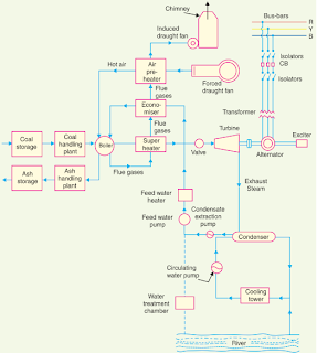
A steam power station basically works on the Rankine cycle. Steam is produced in the boiler by utilising the heat of coal combustion. The steam is then expanded in the prime mover (i.e.., steam turbine) and is condensed in a condenser to be fed into the boiler again. The steam turbine drives the alternator which converts mechanical energy of the turbine into electrical energy. This type of power station is suitable where coal and water are available in abundance and a large amount of electric power is to be generated.
Steam Power Plant Schematic Diagram:
Although steam power station simply involves the conversion of the heat of coal combustion into electrical energy, yet it embraces many arrangements for proper working and efficiency. The schematic diagram of steam power station is shown in the figure below. The whole arrangement can be divided into the following stages for the sake of simplicity .
1. Coal and ash handling arrangement
2. Steam generating plant
3. Steam turbine
4. Alternator
5. Feed water
6. Cooling arrangement
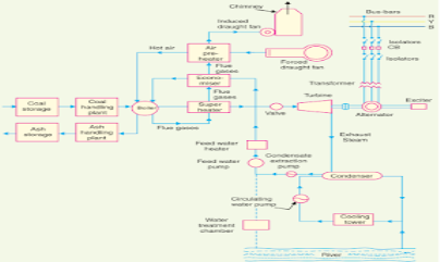
Layout of steam power station or steam power generation plant
The common type of domestic refrigerator has a cabinet shaped with compressor, the condenser and receiver fitted in their basement. The expansion valve and evaporator coils are exposed in the storage cabinet with the pipings, carrying liquid refrigerant passing through the body.
Generally, methylene chloride, Freon-12, and Freon-11 are used as the refrigerants.
Refrigeration is not only provided with double-walled cabinet packed with materials having high thermal insulation such as fiberglass, cork or expanded rubber but also all around the inside of door flap soft rubber seal is used which makes the cabinet airtight.
Also the door is provided with automatic closing mechanism door hinges are provided in such a way that door flap when left in open position automatically comes to closing position due to gravity and as it approaches closing position it is attracted by the magnetic strip fitted behind the sealing rubber ring and thus the door is closed with snap action.
All this is done to prevent leakage of atmospheric heat inside the refrigerator. The main precaution to be taken is that very hot things should not be put in the refrigerator if it is done it will quickly evaporate the refrigerant in evaporator coils producing a large vapour pressure increasing the duty of the compressor. It may damage the motor, which is short-time rated.
Parts of refrigerator:
The refrigerator can be categorized into two categories: internal and external.
The internal parts are ones that carry out actual working of the refrigerator. Some of the internal parts are located at the back of the refrigerator, and some inside the main compartment of the refrigerator.
1) Refrigerant:
The refrigerant flows through all the internal parts of the refrigerator. It is the refrigerant that carries out the cooling effect in the evaporator. It absorbs the heat from the substance to be cooled in the evaporator (chillier or freezer) and throws it to the atmosphere via condenser. The refrigerant keeps on recirculating through all the internal parts of the refrigerator in cycle.
2) Compressor: The compressor is located at the back of the refrigerator and in the bottom area. The compressor sucks the refrigerant from the evaporator and discharges it at high pressure and temperature. The compressor is driven by the electric motor and it is the major power consuming device of the refrigerator.
3) Condenser: The condenser is the thin coil of copper tubing located at the back of the refrigerator. The refrigerant from the compressor enters the condenser where it is cooled by the atmospheric air thus losing heat absorbed by it in the evaporator and the compressor. To increase the heat transfer rate of the condenser, it is finned externally.
4) Expansive valve or the capillary: The refrigerant leaving the condenser enters the expansion devise, which is the capillary tube in case of the domestic refrigerators. The capillary is the thin copper tubing made up of number of turns of the copper coil. When the refrigerant is passed through the capillary its pressure and temperature drops down suddenly.
5) Evaporator or chiller or freezer: The refrigerant at very low pressure and temperature enters the evaporator or the freezer. The evaporator is the heat exchanger made up of several turns of copper or aluminium tubing. In domestic refrigerators the plate types of evaporator is used as shown in the figure above. The refrigerant absorbs the heat from the substance to be cooled in the evaporator, gets evaporated and it then sucked by the compressor. This cycle keeps on repeating.
6) Temperature control device or thermostat: To control the temperature inside the refrigerator there is the thermostat, whose sensor is connected to the evaporator. The thermostat setting can be done by the round knob inside the refrigerator compartment. When the set temperature is reached inside the refrigerator the thermostat stops the electric supply to the compressor and compressor stops and when the temperature falls below certain level it restarts the supply to the compressor.
7) Defrost system: The defrost system of the refrigerator helps removing the excess ice from the surface of the evaporator. The defrost system can be operated manually by the thermostat button or there is automatic system comprising of the electric heater and the timer. Those were the some internal components of the domestic refrigerator; now let us see the external parts.
External visible Parts of the Refrigerator
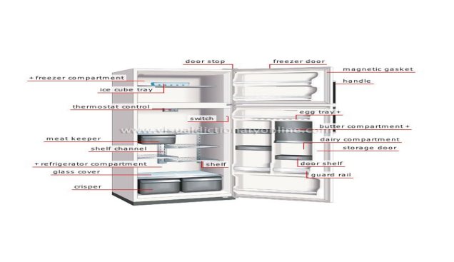
The external parts of the compressor are the parts that are visible externally and used for the various purposes. The figure below shows the common parts of the domestic refrigerator and some them are described below:
1) Freezer compartment: The food items that are to be kept at the freezing temperature are stored in the freezer compartment. The temperature here is below zero degrees Celsius so the water and many other fluids freeze in this compartment. If you want to make ice cream, ice, freeze the food etc. they have to be kept in the freezer compartment.
2) Thermostat control: The thermostat control comprises of the round knob with the temperature scale that help setting the required temperature inside the refrigerator. Proper setting of the thermostat as per the requirements can help saving lots of refrigerator electricity bills.
3) Refrigerator compartment: The refrigerator compartment is the biggest part of the refrigerator. Here all the food items that are to be maintained at temperature above zero degree Celsius but in cooled condition are kept. The refrigerator compartment can be divided into number of smaller shelves like meat keeper, and others as per the requirement.
4) Crisper: The highest temperature in the refrigerator compartment is maintained in the crisper. Here one can keep the food items that can remain fresh even at the medium temperature like fruits, vegetables, etc.
5) Refrigerator door compartment: There are number of smaller subsections in the refrigerator main door compartment. Some of these are egg compartment, butter, dairy, etc.
6) Switch: This is the small button that operates the small light inside the refrigerator. As soon the door of the refrigerator opens, this switch supplies electricity to the bulb and it starts, while when the door is closed the light from the bulb stops. This helps in starting the internal bulb only when required.
Working Principle of domestic refrigerator:
The refrigerator works on the vapour compression refrigeration cycle. The refrigerant vapour is first compressed in the compressor. The compressor is a special one known as the hermetic compressor. In this unit, the compressor is sealed casing along with an electrical motor to run. This sealing prevents leakage of refrigerant and lubrication oil. The pressure and temperature of the refrigerant increases after compression and is subsequently condensed in a condenser. In the condenser, the refrigerant rejects heat to a coolant and cools down and finally gets condensed. The condensate is then allowed to pass through capillary to reduce temperature and pressure by expansion of refrigerant. The refrigerant is filtered before entering the capillary tube. The pressure of the refrigerant, when it leaves the capillary, is maintained above atmospheric and temperature corresponds to saturation temperature so that the refrigerant can absorb heat in the evaporator. The refrigerant enters the evaporator and is heated by the heat absorbed from the body or space thereby producing the refrigeration effect. The vapour refrigerant enters the compressor again and the cycle is completed.
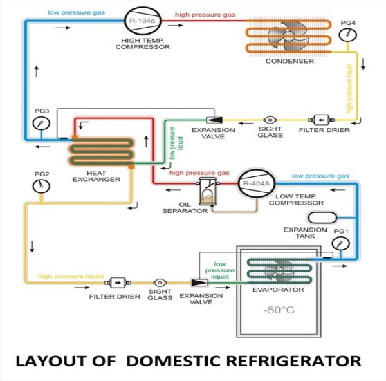
When power to the compressor is switched on, a humming sound is heard and the refrigerator is functional. The refrigerant flows through its circuit and ice is produced in the freezer. Frost, i.e., moisture from ambient air, gets deposited on the evaporator coil. Defrosting removes this frost. The water from defrosting is collected in a tray to be removed manually. Articles to be refrigerated are placed on shelves. Fruits and vegetables, which contain moisture, are stored at the base. The temperature here is around 8°C. Thus there are temperature gradients in the refrigerator, negative temperature in the freezer and positive temperature at the base.
Applications of Refrigerator
As we studied in above article a refrigerator is a device used to maintain the lower temperature than that of its surroundings by absorbing heat from the refrigerated space and reject it into the surrounding. In past time the main use of refrigerator was only produce ice which is used for many purposes but now days the application of the refrigerator increases day by day as the new technology develops.
Some major application of the refrigerator are given as follow
Heat pump
A heat pump is a device which applies external work to extract an amount of heat QC from a cold reservoir and delivers heat QH to a hot reservoir. A heat pump is subject to the same limitations from the second law of thermodynamics as any other heat engine and therefore a maximum efficiency can be calculated from the Carnot cycle. Heat Pumps are usually characterized by a coefficient of performance which is the number of units of energy delivered to the hot reservoir per unit work input.

The coefficient of performance (CP) for a heat pump is the ratio of the energy transferred for heating to the input electric energy used in the process. In reference to the standard heat engine illustration, the coefficient is defined by
Coefficient of performance = QH/W
There is a theoretical maximum CP, that of the Carnot cycle :

For a refrigerator, however, the useful quantity is the heat extracted, QC , not the heat exhausted. Therefore, the coefficient of performance of a refrigerator is expressed as

Internal combustion (IC) engines- the fuel used undergoes combustion inside the engine in the presence of air. The product produced by the combustion becomes the working fluid of the engine.
Internal combustion engines have higher efficiency and are lighter in weight in comparison to the power developed. They have become very much suitable for mobile applications. With all these advantages, IC engines have become universal means of power generation and very much popular.
Classification of Internal Combustion (IC) Engine:
Internal combustion engines may be classified on the basis of:
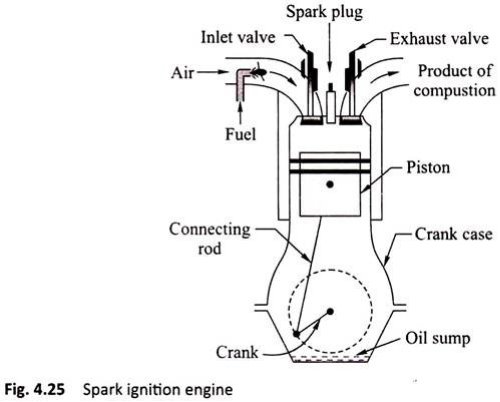
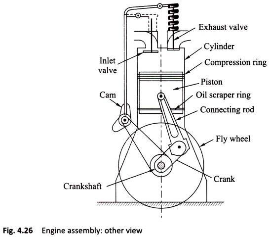
An assembled diagram with various parts of an IC engine is shown in Figure
i. Engine Cylinder:
It is a cylindrical vessel in which the fuel is burnt and the product of combustion gets expanded to develop power. Inside the cylinder, there is a sleeve fitted called the cylinder liner of hard metal. A piston makes reciprocating motion inside the cylinder.
ii. Cylinder Head:
It is fitted at the top of cylinder to cover the cylinder. The cover provides the accommodation of inlet valve, exhaust valve, and spark plug (in SI engine) or injector (in CI engine).
iii. Piston:
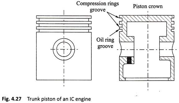
Piston is a tightly fitted block generally known as trunk piston which receives the gas pressure inside the engine cylinder. The gas pressure is transmitted to the crankshaft through the connecting rod (Fig. 4.27).
Piston Rings:
There are two types of rings fitted on the circumferential groove provided on the outer surface of piston (Fig. 4.28):

Compression Ring:
Compression rings maintain a gas tight contact between cylinder and the piston.
Oil Scraper Ring:
Lubrication is required in the cylinder sleeve surface to reduce frictional forces. However, the excess oil needs to be removed. Thus, the ring will have a groove which removes this excess lubricating oil from the sleeve of the cylinder into the crank case.
Connecting Rod:
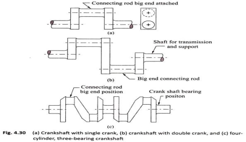
Connecting rod transmits the force from piston to crankshaft. It helps in converting the reciprocating motion to rotary motion. It has two ends—small end and big end. The small end is connected with piston with a gudgeon pin. The big end is connected with crankshaft (Fig. 4.29).

Crank and Crankshaft:
It converts the reciprocating motion of the piston to rotary motion of the shaft. The crankshaft is enclosed inside a crank case [Figs. 4.30(a) – 4.30(c)].
Valves:
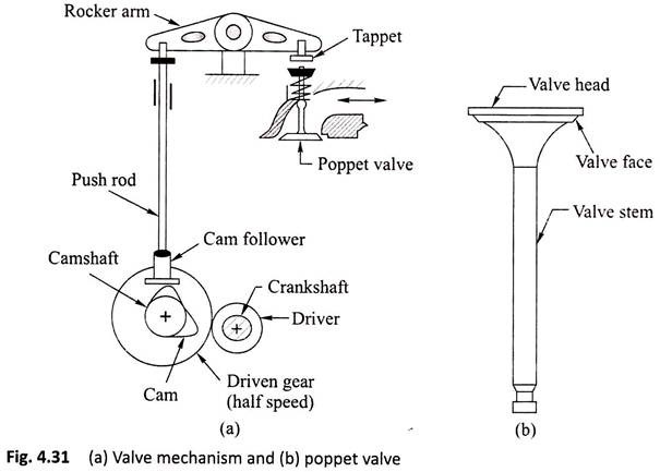
These valves are also called poppet valves.
There are two types of valves:
i. Suction valve and
ii. Exhaust valve.
i. Suction Valve:
This valve controls the mixture of petrol vapours and air in SI engines and only air in CI engines.
ii. Exhaust Valve:
It controls the flow of exhaust gas from the cylinder. The product of combustion is to be expelled out by opening this valve for starting fresh cycle.
The valves are operated by cam mechanism with the help of rocker arms in a single cylinder engine and by camshaft in a multi cylinder engine [Figs. 4.31(a) and 4.31(b)]. In four-stroke engines, the rotation of the camshaft is half of rotation of the crankshaft.
Fly Wheel:
Fly wheel is a heavy wheel mounted on engine shaft. It has large moment of inertia and, hence, absorbs energy during operation and supplies back the energy to the engine when required. Thus, this removes the cyclic fluctuation and maintains uniform rotation of the crankshaft. A single cylinder engine will have a large fly wheel, whereas a multi cylinder engine will have a smaller fly wheel.
Crank Case:
It is fitted in the lower part of the engine cylinder to cover crankshaft and also to store the lubricating oil known as oil sump.