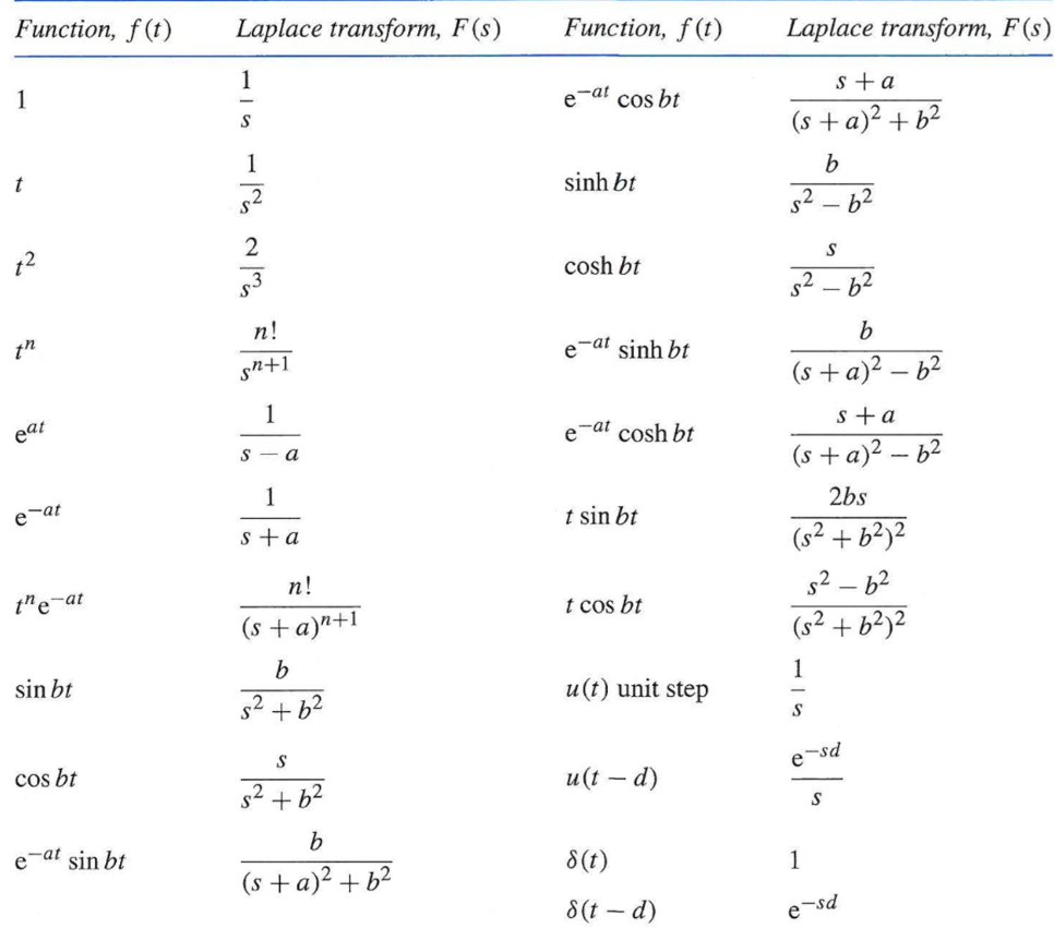
Unit - 4
Electrical Circuit Analysis Using Laplace Transforms
It is a technique for solving differential equations. The time domain differential equations are transformed into algebraic equation of frequency domain. After solving the algebraic equation in frequency domain, the result then is finally transformed to time domain form to achieve the ultimate solution of the differential equation.
The Laplace Transform is given as
F(s)= dt
dt
The advantages of Laplace Transform are:
1) It is systematic.
2) It gives total solution (transient and sustained solution) in one operation.
3) The initial conditions are automatically specified in the transformed equations.
Key takeaway
There are many functions which do not have Laplace Transforms. These functions are not generally used in analysis of linear systems. But some conditions can be defined to get Laplace transformation of such functions. The Dirichlet condition defines the necessary condition for transformation of some functions such as:
a) The function should be continuous. The function should be single-valued.
b) The function must be of exponential order.
Properties of Laplace Transform:
1) Linearity Property:
If f1(t) and f2(t) are two functions of time. Then, in domain of convergence
L [a f1(t)+b f2(t)] =a + b
+ b =aF1(s)+bF2(s)
2) Differentiation Property:
If x(t) is function of time then Laplace transform of nth derivative is given as

3) Integration Property:
The Laplace of nth order integral is given as
L [ ]=
]= +
+
L[f-n(t)] = +
+ +
+ +……….
+……….
As 
 ……...=0. Hence
L[f-n(t)] =
Key takeaway
4.2 Analysis of electrical circuits using Laplace Transform for standard inputs
LAPALACE TRANSFORM:
If LT[f(t)] = F(s)
Where F(s)= dt
dt
f(t) F(s)
F(s)

 sF(s)-f (0-)
 f(t)
f(t) S2F(s)-sf (0-)-f’ (0-)
Now, we find Laplace for 
 =
= +
+
Now if f(t)=ic(t) [current through capacitor]
 =
= +
+
 =
= +
+
= [q (0)-q ( )] +
)] +
= [q (0)-0] +
Multiplying both sides by 1/C
 =
= +
+
Vc(t)= +
+
Vc(t)=Vc (0) +
By Laplace Transform
Vc(s)= +
+
Vc(s)= +
+
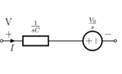
Fig. Laplace transformed circuit for C
Now by source conversion

Fig. Source transformed circuit for C
 =
= +
+
Now if f(t)=VL(t) [voltage across inductor]
 =
= +
+
 =
= +
+
= -
- ]+
]+
= -0] +
-0] +
Multiplying both sides by 1/L

 =
= +
+
iL(t)=iL (0) +
By Laplace Transform
IL(s)= +
+
IL(s)= +
+
NOTE: Voltage------->Series circuit
Current------->Parallel circuit
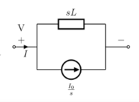
Fig. Laplace transformed circuit for L
By source transformation

Fig. Source transformed circuit for L
Current through capacitor
iC(t)=
IC(s)=C[sVc(s)-Vc (0)]
Vc(s)= +
+
Voltage about inductor,
VL(t)=
VL(s)=L[sIL(s)-iL (0)]
IL(s)= +
+
Key takeaway
Vc(s)= +
+
IL(s)= +
+
Que For given RL circuit find the differential equation for current i?
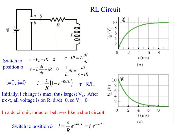
Fig. Series RL circuit
After switch is closed applying KVL
 =0
=0
This is first order homogeneous differential equation so
 dt
dt
Integrating both sides
ln i=  t+K
t+K
taking antilog of both sides
i=k
At t=0
i (0) = =I0
=I0
 =ke0
=ke0
The particular solution is given as
i=  for t≥0
= for t<0
Ques: Find IL (0) for the given circuit below
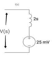
Sol: From above circuit
L = 2H
LiL (0) = 25 mv
IL (0) = 12.5 m A
Que: Find value across capacitor?
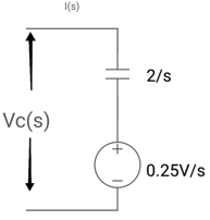
Sol: From above circuit we can write
1/cs = 2/s
C=1/2f
Vc (0)/s = 0.25v/s
Vc (0) = .25v
Ques: Find voltage across capacitor?
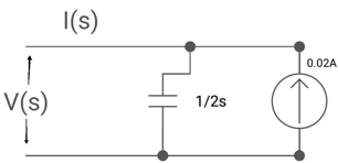
Sol: 1/cs = 1/2S
C=2F
CVc (0) = 0.02
Vc (0) = 0.01V
Que:
(a) switch is at before moving to position = at t= 0, at t= 0+, i1(t) is
(a) –V/2R (b) –V/R (c) – V/4R

Sol:
I1(t) L.T I1(s)
I2(t) L.T I2(s)
then express in form
[ I1(s)/I2(s)] [:] = [:]
Drawing the ckl at t = 0-
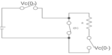
:. The capacitor is connected for long
Vc1(0-) = V
iL (0-) =0
Vc2(0-) =0
at t= 0+
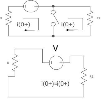
i1 (0+) = -V/2R
for t>0 the circuit is
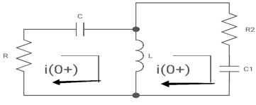
Apply KVL
-R i1(t) -1/c  dt -L
dt -L =0
=0
Also, we can deduce i1(t)- i2 (t) = iL(t)
-Ri1(t) -1/c  - L
- L = 0
= 0
-RI1(s)-[ -
- ]-L[sI1(s)-iL (0-)] =0
- RI1(s)- -
-  -s L I2(s)=0
 - s L I2(s)= -
  (1)
(1)
Again
-Ri2(t)) -1/c  dt -L
dt -L =0
=0
-Ri1(t) -1/c  - L
- L = 0
= 0
Taking Laplace Transform
-RI2(s)- [ -
- ]- L [s IL(s)- iL (0-)] =0
-RI2(s)-  -
- Ls [ I1(s)- I2(s)] =0
 - s L I1(s)=0 (2)
Hence in matrix representation

 =
= 
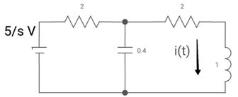
Ques: All initial conditions are zero i(t) L.T, I(s), then find I(s)?
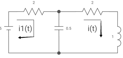
Sol: Drawing Laplace circuit
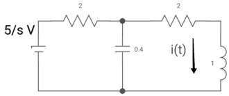
(2+S) 11 2/S
Zeq = [(2+S)2/S]/[2+S+2/S] =[2(S+2)]/[S2+2s+2]
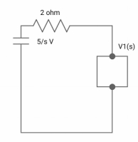
V1(s) = [5/S{2(S+2)/S2+2S+2}]/[2+{2(S+2)/ S2+2S+2}]
V1(s) = [5(S+2)/S]/ [S2+ 3S +4]
I(s) = V1(s)/(S+2) = (5/S)/(S2+35+4)
Singularity functions are discontinuous functions or their derivatives are discontinuous. A singularity is a point at which a function does not possess a derivative. In other words, a singularity function is discontinuous at its singular points. Hence a function that is described by polynomial in t is thus a singularity function. The commonly used singularity functions are
Step Function,
Ramp Function, and
Impulse Function
The convolution theorem states that f1(t) and f2(t) are two-time functions which are zero for t<0 and if Laplace transform are F1(s) and F2(s)then the transform of convolution of f1(t) and f2(t) is the product of individual transforms F1(s) and F2(s).
f(t) = f1(t)*f2(t) = 
= f2(t)*f1(t) = 
He convolution theorem of
Laplace transform is
L[f1(t)*f2(t)] = L[f2(t)*f1(t)] = F1(s)F2(s)
The Laplace Transformation transforms convolution into multiplication.
The graphical presentation of the convolution integral helps in the understanding of every step in the convolution procedure. According to the definition integral, the convolution procedure involves the following steps:
1) Apply the convolution duration property to identify intervals in which the convolution is equal to zero.
2) Flip about the vertical axis one of the signals (the one that has a simpler form (shape) since the commutativity holds), that is, represent one of the signals in the time scale.
3) Vary the parameter from - to +
to + , that is, slide the flipped signal from the left to the right, look for the intervals where it overlaps with the other signal, and evaluate the integral of the product of two signals in the corresponding intervals.
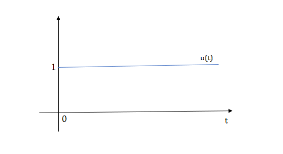
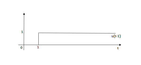
1) Step Function:
U(t)=1 t≥0
=0 t<0
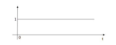
Fig. Step Signal
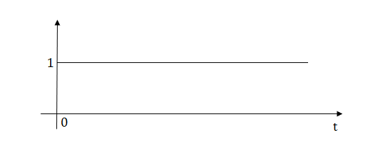
Fig. Shifted unit step signal
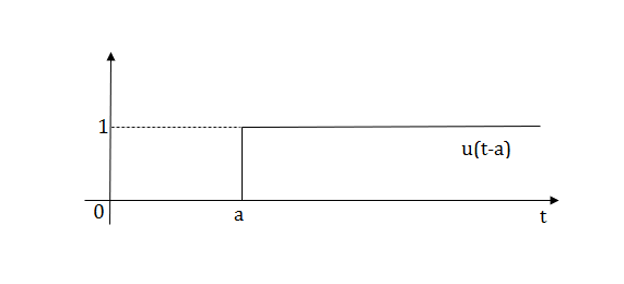
Fig. unit step signal -u(t)
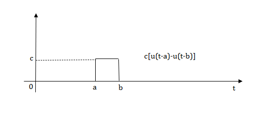
2) Pulse Function:
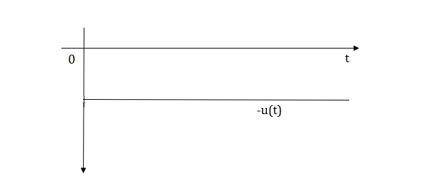
Fig. Pulse signal
L[u(t)] = =
=
f(t)<—>F(s)
f(t-a) = F(s)
F(s)
L[u(t-a)] =
Laplace transforms of pulse
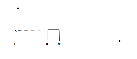
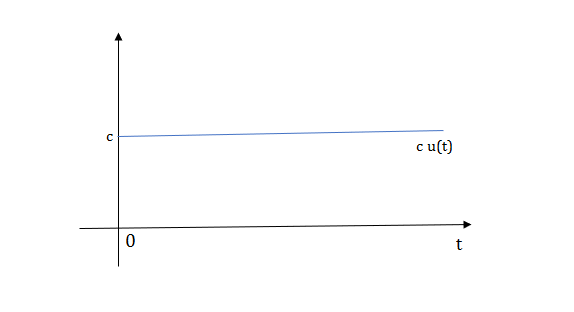
Fig. Shifted Pulse signal
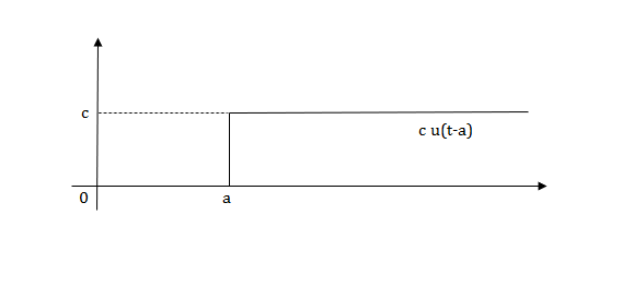
Fig. Shifted Pulse signal
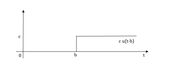
Fig. Final required Pulse signal
Q.1) Write equation for given waveform
Sol:
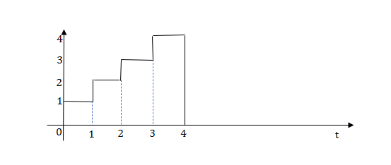


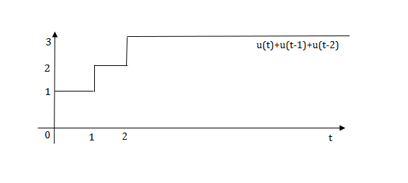
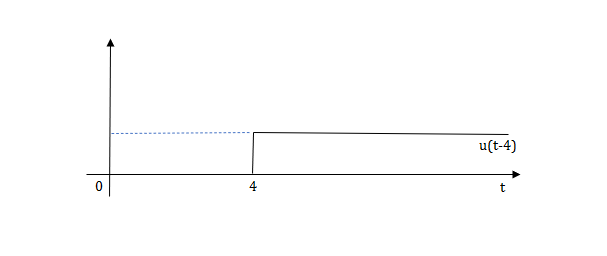
The final equation is=u(t)+u(t-1) +u(t-2) +u(t-3)-4u(t-4)
As the waveform is stopped at t=4 with amplitude 4, so we have to balance that using -4u(t-4).
Ramp function:

Fig. Ramp Function
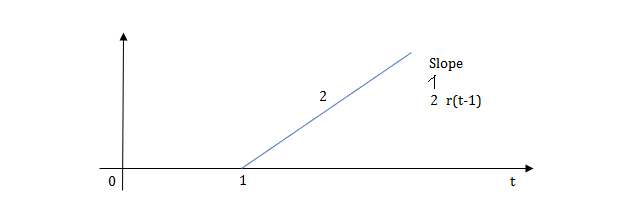
Fig. Shifted Ramp Function
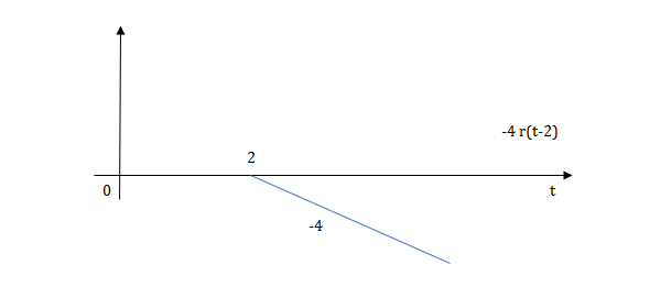
Fig. Shifted Ramp Function
L[r(t)] =
R(t)=tu(t)
R(t)=∫u(t)
Impulse Signal:
This signal has zero amplitude everywhere expect at the origin. fig below shown the representation of Impulse signal.
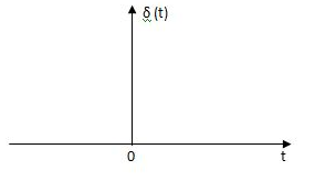
Fig. Impulse Function
The mathematical representations
A (t) = 0 for t ≠0
 dt = A e
Where A represent energy or area of the Laplace Transform of Impulse signal is
L [A (t)] = A
The transfer function of a linear time invariant System is the Laplace transform of the impulse response of the system
Q.3) Write the equation for the given waveform?
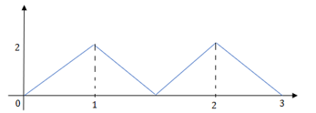
Sol: Calculating slope of above waveform
Slope for (0,0) and (1,2)
a1 slope= =2
=2
a2 slope= =-4
=-4

a3 slope =4 and a4= -2
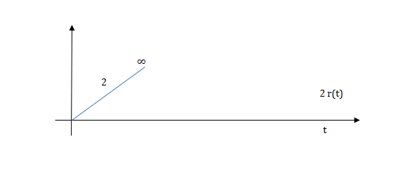

At t=1 slope changes from 2 to -4 so we need to add -6r(t-1) to 2r(t) to get the slope of -4.
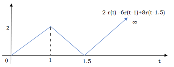
At t=1.5 slope changes from -4 to 4 so adding 8r(t-1.5) to get slope of 4
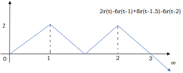
At t=2 slope changes from +4 to -2 so we add -6r(t-2). But we need to stop the waveform at t=3. Hence, we have to make slope 0. Which can be done by adding +2r(t-3). Final equation is given as 2r(t)-6r(t-1.5) +8r(t-1.5)-6r(t-2) +2r(t-3)
The Laplace inverse of any function H(s) is given by
L-1 H(s) = h(t)
Properties of Inverse Laplace transform are
Linearity property
L-1 {aH1(s)+b H2(s)} = ah1(t)+bh2(t)
Shifting property
L-1 H(s) = h(t)
L-1 H(s-a) = eat h(t)
If L-1 H(s) = h(t)
Then, L-1 [H(s)/s] = 
If L-1 H(s) = h(t)
L-1 e-at H(s) = u(t-a). h(t-a)
Key takeaway

Que: The switch is at before moving to position = at t= 0, at t= 0+, i1(t) is
(b) –V/2R (b) –V/R (c) – V/4R (d) 0
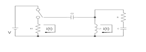
Sol: -
I1(t) L.T I1(s)
I2(t) L.T I2(s)
then express in form
[ I1(s)/I2(s)] [:]. [:]
Drawing the ckl at t = 0-
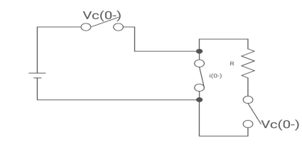
Fig. circuit at t=0-
:. The capacitor is connected for long
Vc1(0-) = V
iL (0-) =0
Vc2(0-) =0
at t= 0+
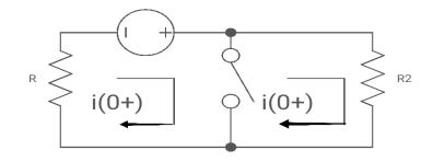
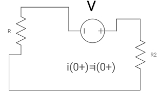
Fig. Circuit at t=0+
i1 (0+) = -V/2R
for t>0 the circuit is
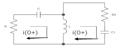
Fig. KVL in Circuit
Apply KVL
-R i1(t) -1/c  dt -L
dt -L =0
=0
Also, we can deduce i1(t)- i2 (t) = iL(t)
-Ri1(t) -1/c  - L
- L = 0
= 0
-RI1(s)-[ -
- ]-L[sI1(s)-iL (0-)] =0
- RI1(s)- -
-  -s L I2(s)=0
 - s L I2(s)= -
  (1)
(1)
Again
-Ri2(t)) -1/c  dt -L
dt -L =0
=0
-Ri1(t) -1/c  - L
- L = 0
= 0
Taking Laplace Transform
-RI2(s)- [ -
- ]- L [s IL(s)- iL (0-)] =0
-RI2(s)-  -
- Ls [ I1(s)- I2(s)] =0
 - s L I1(s)=0 (2)
Hence in the matrix representation

 =
= 
Ques: All initial conditions are zero i(t) I(s), then find I(s)?
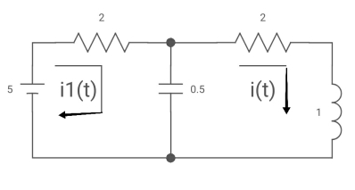
Sol: Drawing Laplace circuit
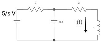
(2+S) 11 2/S
Zeq = [(2+S)2/S]/[2+S+2/S] =[2(S+2)]/[S2+2s+2]
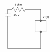
V1(s) = [5/S{2(S+2)/S2+2S+2}]/[2+{2(S+2)/ S2+2S+2}]
V1(s) = [5(S+2)/S]/ [S2+ 3S +4]
I(s) = V1(s)/(S+2) = (5/S)/(S2+35+4)

a) All coefficients of p(s) and q(s) should be real and positive for q(s)
b) The poles must be conjugate if imaginary or complex.
c) The real part of poles must be negative or new of zero than pole must be simple.
d)The degree of p(s) could be zero and it is independent of q(s) for example f(s) 5/ (s3+3s+1)
e) q(s) cannot have missing terms between the highest and lowest degree unless all the even or all odd terms are missing
f) degree of q(s) >, p(s)
g) p(s) may have missing terms between the highest and lowest degree and its coefficients could be negative.
Key takeaway
The degree of q(s) >p(s).
All coefficients of p(s) and q(s) should be real and positive for q(s)
Let us consider the following transfer function

a, b- coefficient with are real and positive
Features of poles and zeros of network function.
a) The network function is described by poles and zeros.
b) The zeros of the network exit for the complex frequencies where N(s)=0
c) The poles of the network exit for the complex frequencies where N(s)=o
d)The number of poles is equal to some zeros considering types poles and zeros which at infinity.
e) when n>m, poles at infinity has a degree(n-m)
f) When m>n, zeros at infinity with a degree (m-n)
g) The time variation response of the network is determined through the poles.
h) The magnitude of response is determined by poles and zeros of the network function.
i) If q(s) =0, is the characteristics equation of N(S).
J) Capacitor is represented as (ʊ)=1/cs so, for
S = 0, It behaves like open circuits
S= behaves as a short circuit
k) for inductor z(s) = Ls so, for
s= o It behaves short circuit
s = It behaves as given circuits
Key takeaway
The zeros of the network exit for the complex frequencies where N(s)=0
The poles of the network exist for the complex frequencies where N(s)=o
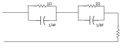
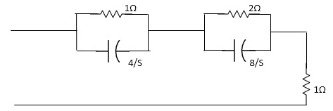
Que) For the network shown, find driving point input impedance. plot the pole-zero patterns for each as well.
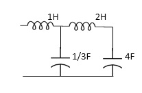
Fig (1). Circuit Diagram
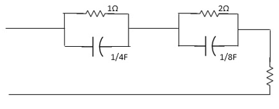
Fig (2). Circuit Diagram
Solution - For Fig 22(1) taking L.T we have
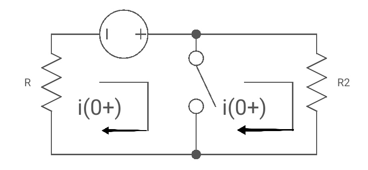
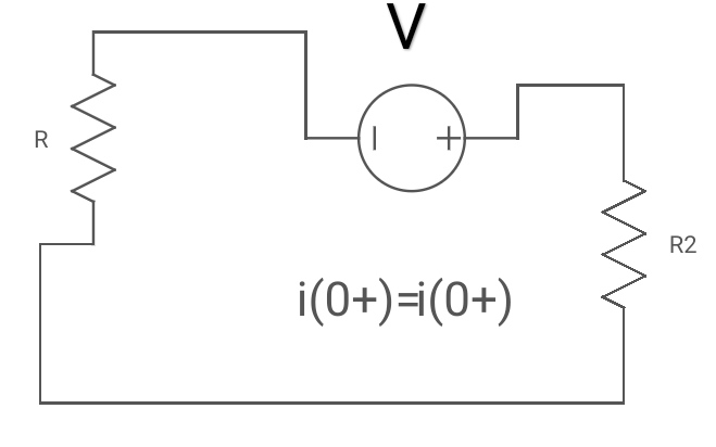
Fig Laplace for above figure (1) with roots
Z11= 1+ 1 /S/3+1/25+1/1/4S
=1+ 1/ 5/3+1/6S
=1+ 18S/6S2+3
Z11=6S2+3+18S/ 6S2+3 =2S2+6S+2/2S2+1
Zeros of equations are taking lt. of circuit b)
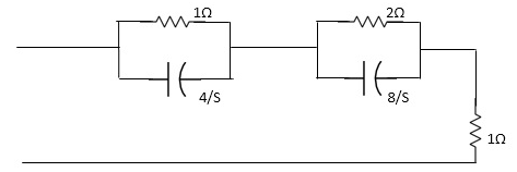
Fig. Laplace for Fig (2)
Z11= 1*4/5
1+4/5+2.8/3/2+8/5+1
=4/5+4 + 16/ 25+8+1
= 4/5+4+8/5+4+1
=s+12+4/ (5+4)
Z11= S+16/(S+4)
For zeros of system
s+16=0
s=-16
for poles of system
s+4=0
s=-4
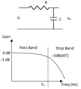
For RC LPF the reactance of ‘C’ is very high at low frequency so, capacitor acts as open circuit and blocks i/p signal Vi until cut-off frequency is reached.
Cut-off frequency for a LPF is that frequency at which the voltage at output equals 70.7% of input voltage ( -3 dB point).
LPF are used to filter noise from circuit.
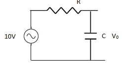
Q –A LPF circuit consisting of a resistor of 40KΩ in series with capacitor 47nF across a 10V sinusoidal supply. Calculate VO at frequency 1Kz?

Sol:
R = 40KΩ
C = 47nF
Vi = 10V
F = 1000 Hz
For LPF,
Capacitive Reactance is XC
The output voltage is given as
VO = Vi
XC =  =
= 
XC = 3.386KΩ
VO = 
=10 x
= 10 x
VO = 0.843 V
(b) RL LPF
FC = R / 2nt
VO = Vi
Characteristic impedance of low pass
A Basic LPF circuit can be designed using passive elements R, L and C. The circuit is having single ‘R’ in series with capacitor ‘C’.
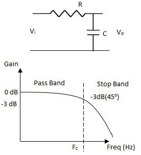
For RC LPF
VO = = Vi x  fC = 1 / 2∏RC
But Z =  Phase shift φ = -cot(2∏FC)
And XC =
VO – output voltage
Vi – input voltage
Z – Impedance
XC – Capacitive Reactance
FC – cut off Frequency
For RC LPF the reactance of ‘C’ is very high at low frequency so, capacitor acts as open circuit and blocks i/p signal Vi until cut-off frequency is reached.
Cut-off frequency for a LPF is that frequency at which the voltage at output equals 70.7% of input voltage ( -3 dB point).
LPF are used to filter noise from circuit.
Q –A LPF circuit consisting of a resistor of 40KΩ in series with capacitor 47nF across a 10V sinusoidal supply. Calculate VO at frequency 1Kz?
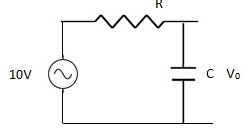
Sol:
R = 40KΩ
C = 47nF
Vi = 10V
F = 1000 Hz
For LPF,
Capacitive Reactance is XC
The output voltage is given as
VO = Vi
XC =  =
= 
XC = 3.386KΩ
VO = 
=10 x
= 10 x
VO = 0.843 V
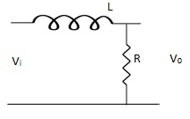
(b) RL LPF
FC = R / 2nt
VO = Vi
Comparison of RL – RC circuits
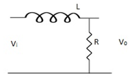
Q – An RL LPF consists of 5.6mH coil a 3.3 KΩ resistor. The output voltage is taken across resistor. Calculate the critical frequency?
Sol Given:
L = 5.6 x 10⁻³ H
R = 3.3 x 10³Ω
For RL LPF
F = =
= 
F = 93.78 KHz
Q – A sinusoidal voltage with peak-to-peak value of 10 V is applied to an RC LPF. If reactance at input is zero, find output voltage?
Sol:
VO = 
XC = 
F = XC = 0, F ->∞
Hence, VO = 0V.
Q. An RC – LPF consists of 120 Ω resistor and 0.02 µF capacitor. The output is taken through capacitor. Calculate the critical frequency?
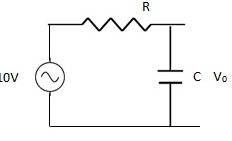
For RC LPF FC is given as
FC= =
=
FC = 66.31 KHz
High pass
(a). The RC – HPF circuits is shown below, which is having capacitor at input and resistor at output.
Reactance of capacitor is very high at low frequency.
XC =
XC when F (C acts as open circuit)
XC when F (C acts as short circuit)
FC = 
Phase shift = Cot 
VO =Vi
VO = Vi
At low F: XC ->∞ VO = 0
At high F: XC -> 0 VO = Vi
Q An RC HPF with input capacitor 10nf and the output resistor of 10K Ω. Find the cut off frequency.
Sol:

FC = =
= 
FC = 15.915 Hz
Q. Calculate the break point (FC) for a simple passive HPF consisting of 82pF capacitor connected in series with 240 KΩ resistor?
Sol:
FC = =
= 
FC = 8KHz
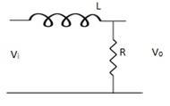
(b). RL – HPF:
The basic RL HPF is shown below. The inductors pass low frequency signals with very little resistance, and offers great resistance to high frequency signals.
VO = 
FC = 
Q. For a RL HPF consists of 470Ω resistor and 600 mH coil output is taken across coil. Calculate the cut off frequencies.
Sol:
FC =  =
= = 125 Hz
Que) A series RL low-pass filter cutoff frequency is 2KHz. R=5KΩ Find the inductor value. Find |H(jω) | at 50 KHz?
Sol: The cut-off frequency is  c = R/L
L= 5000/2000 =2.5Hz
|H(jω) | = 
Substitute values in above equation for 50KHz we get
|H(jω) | = 0.0635
Definition: it is defined as the phenomenon which takes place in the series or parallel R-L-C circuit which leads to unity power factor
Voltage and current in R – L - C circuit. Are in phase with each other.
Resonance is used in many communicate circuit such as radio receiver.
Resonance in series RLC series resonance in parallel RLC anti resonance / parallel resonance.
Xc =  - capacitive reactance
At a particular frequency ȴ = fr, the Inductive and capacitive reactance are exactly equal
 XL = XC ……at ȴ = fr
Ie  L =
L = 
 fr2 =
fr2 = 
 fr =
fr =  H2
H2
And  = wr =
  rad/sec
Quality factor / Q factor
The quality of resonance circuit is measured in terms of efficiency of L and C to stare energy and the efficiency of L and C to store energy as measured in terms of a factor called quality factor or Q factor it is expressed as
Q =  and Q =
The sharpness of tuning of R-L-C series circuit or its selectivity is measured by value of Q. as the value of Q increases, sharpness of the curve also increases and the selectivity increases.
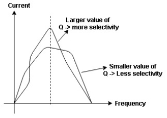
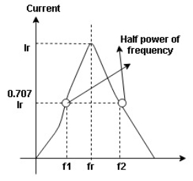
Fig. Bandwidth
Bandwidth (BW) = f2 = b1
 and
and  are the frequency at which the power delivered to the resistor is reduced to 50% of the power delivered to it at resonance
  these frequencies are called as half power frequency
Bw = fr/Q
Resonance in Parallel circuit:
When a coil is in parallel with a capacitor, as shown below. The circuit is said to be in resonance.
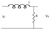
Fig. Parallel Circuit
The resonant frequency for above circuit is fr =  Hz
Hz
The current at resonance is I=
The value L/RC is known as dynamic impedance.
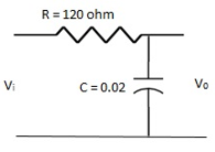
Fig. Bandwidth
The current at resonance is minimum. The circuits admittance must be at its minimum and one of the characteristics of a parallel resonance circuit is that admittance is very low limiting the circuits current. Unlike the series resonance circuit, the resistor in a parallel resonance circuit has a damping effect on the circuit bandwidth making the circuit less selective.
Also, since the circuit current is constant for any value of impedance, Z, the voltage across a parallel resonance circuit will have the same shape as the total impedance and for a parallel circuit the voltage waveform is generally taken from across the capacitor.
Bandwidth and selectivity:
 and
and  are the frequency at which the power delivered to the resistor is reduced to 50% of the power delivered to it at resonance
  these frequencies are called as half power frequency
Bw = fr/Q
Q =  =
=  fCR = R
Resonant Frequency:
The resonant frequency for parallel resonant circuit is given as
fR= 
Where L= inductance of the coil
C = is the capacitance
Rs = Resistive value of coil.
Examples
Que) A coil takes a current of 6A when connected to 24V dc supply. To obtain the same current with 50HZ ac, the voltage required was 30V. Calculate inductance and p.f of coil?
Sol: The coil will offer only resistance to dc voltage and impedance to ac voltage
R =24/6 = 4ohm
Z= 30/6 = 5ohm
XL = 
= 3ohm
cosφ =  = 4/5 = 0.8 lagging
Que) The potential difference measured across a coil is 4.5V, when it carries a dc current of 8A. The same coil when carries ac current of 8A at 25Hz, the potential difference is 24V. Find current and power when supplied by 50V,50Hz supply?
Sol: R=V/I= 4.5/8 = 0.56ohm
At 25Hz, Z= V/I=24/8 =3ohms
XL = 
= 2.93ohm
XL = 2 fL = 2
 x 25x L = 2.93
L=0.0187ohm
At 50Hz
XL = 2x3 =6ohm
Z =  = 5.97ohm
I= 50/5.97 = 8.37A
Power = I2R = 39.28W
Que) A coil having inductance of 50mH an resistance 10ohmis connected in series with a 25 F capacitor across a 200V ac supply. Calculate resonant frequency and current flowing at resonance?
Sol: f0= = 142.3Hz
I0 = V/R = 200/10 = 20A
Que) A 15mH inductor is in series with a parallel combination of 80ohm resistor and 20 F capacitor. If the angular frequency of the applied voltage is 1000rad/s find admittance?
Sol: XL = 2 fL = 1000x15x10-3 = 15ohm
XL = 1/ C = 50ohm
Impedance of parallel combination Z = 80||-j50 = 22.5-j36
Total impedance = j15+22.5-j36 = 22.5-j21
Admittance Y= 1/Z = 0.023-j0.022 siemens
Que) A circuit connected to a 100V, 50 Hz supply takes 0.8A at a p.f of 0.3 lagging. Calculate the resistance and inductance of the circuit when connected in series and parallel?
Sol: For series Z =100/0.8 = 125ohm
cosφ = 
R = 0.3 x 125 = 37.5ohm
XL =  = 119.2ohm
XL = 2 fL = 2
 x 50x L
119.2 = 2 x 50x L
L= 0.38H
For parallel:
Active component of current = 0.8 cosφ = 0.3x0.3 = 0.24A
R = 100/0.24 =416.7ohm
Quadrature component of current = 0.8 sinφ = 0.763
XL= 100/0.763 = 131.06ohm
L= 100/0.763x2 x50 = 0.417H
References:
Education, 2013.
4. C. K. Alexander and M. N. O. Sadiku, “Electric Circuits”, McGraw Hill Education, 2004.
5. K. V. V. Murthy and M. S. Kamath, “Basic Circuit Analysis”, Jaico Publishers, 1999.
